EP1122150A1 - Motor vehicle power steering device - Google Patents
Motor vehicle power steering device Download PDFInfo
- Publication number
- EP1122150A1 EP1122150A1 EP01400263A EP01400263A EP1122150A1 EP 1122150 A1 EP1122150 A1 EP 1122150A1 EP 01400263 A EP01400263 A EP 01400263A EP 01400263 A EP01400263 A EP 01400263A EP 1122150 A1 EP1122150 A1 EP 1122150A1
- Authority
- EP
- European Patent Office
- Prior art keywords
- steering
- wheels
- vehicle
- angles
- turning
- Prior art date
- Legal status (The legal status is an assumption and is not a legal conclusion. Google has not performed a legal analysis and makes no representation as to the accuracy of the status listed.)
- Withdrawn
Links
Images
Classifications
-
- B—PERFORMING OPERATIONS; TRANSPORTING
- B62—LAND VEHICLES FOR TRAVELLING OTHERWISE THAN ON RAILS
- B62D—MOTOR VEHICLES; TRAILERS
- B62D6/00—Arrangements for automatically controlling steering depending on driving conditions sensed and responded to, e.g. control circuits
- B62D6/002—Arrangements for automatically controlling steering depending on driving conditions sensed and responded to, e.g. control circuits computing target steering angles for front or rear wheels
-
- B—PERFORMING OPERATIONS; TRANSPORTING
- B62—LAND VEHICLES FOR TRAVELLING OTHERWISE THAN ON RAILS
- B62D—MOTOR VEHICLES; TRAILERS
- B62D5/00—Power-assisted or power-driven steering
- B62D5/04—Power-assisted or power-driven steering electrical, e.g. using an electric servo-motor connected to, or forming part of, the steering gear
- B62D5/0418—Electric motor acting on road wheel carriers
-
- B—PERFORMING OPERATIONS; TRANSPORTING
- B62—LAND VEHICLES FOR TRAVELLING OTHERWISE THAN ON RAILS
- B62D—MOTOR VEHICLES; TRAILERS
- B62D5/00—Power-assisted or power-driven steering
- B62D5/04—Power-assisted or power-driven steering electrical, e.g. using an electric servo-motor connected to, or forming part of, the steering gear
- B62D5/0442—Conversion of rotational into longitudinal movement
- B62D5/0454—Worm gears
-
- B—PERFORMING OPERATIONS; TRANSPORTING
- B62—LAND VEHICLES FOR TRAVELLING OTHERWISE THAN ON RAILS
- B62D—MOTOR VEHICLES; TRAILERS
- B62D5/00—Power-assisted or power-driven steering
- B62D5/06—Power-assisted or power-driven steering fluid, i.e. using a pressurised fluid for most or all the force required for steering a vehicle
- B62D5/10—Power-assisted or power-driven steering fluid, i.e. using a pressurised fluid for most or all the force required for steering a vehicle characterised by type of power unit
- B62D5/12—Piston and cylinder
Definitions
- the present invention relates to a device motor vehicle power steering, to control the steering angle of the left and right wheels of at least a steering axle of said vehicle and, more particularly, to such a device comprising a) a control member manual generation of a setpoint for said turning angle, b) turning means said wheels, and c) sensitive regulation means at said set value for controlling said means steering angle so that the actual steering angles wheels are linked to said set value.
- FR-A-2 744 089 and FR-A-2 745 256 are examples of devices including FR-A-2 744 089 and FR-A-2 745 256. As shown in the Figure 1 of the accompanying drawing, these include a steering wheel constituting a manual control member of a generator 2 of a setpoint for the angle of steering the vehicle wheels. This value is determined by the driver of the vehicle, who does turn the handwheel 1.
- the generator 2 can be constituted by a position sensor, of any known type, suitable for form a signal representative of the angular position of the steering wheel.
- This signal is supplied to a regulator 3 which derives from this signal a set value ⁇ c of the steering angle requested by the driver.
- the regulator also receives a signal representative of the real steering angle of the left and right wheels 4,4 'respectively, of a steering axle of a motor vehicle.
- the regulator 3 compares the real and set values of the steering angle and controls an actuation mechanism acting on the orientation of the wheels 4,4 'so that the real steering angle of these wheels coincides with the setpoint angle ⁇ c requested by the driver of the vehicle.
- the regulator 3 also controls force variator 5 acting on the shaft 6 of the flywheel 1 so that the driver finds, on this steering wheel, the friction and restoring forces it experiences when maneuver the steering wheel of a steering device classic, these forces no longer "going up” on the wheel of the device of FIG. 1, mechanically decoupled from the 4,4 'wheels and the means used to maneuver them.
- Power steering devices of the type described above have many advantages and their future is therefore promising: deletion of the column steering, source of serious injury in the event of an accident, elimination of rising vibrations in this column, possible reduction of the flywheel diameter for heavy goods vehicles, coaches and buses, resulting in improved comfort driving, possibility of variation of the reduction in steering wheel angle / steering angle, possibility overlapping automatic steering corrections requested by driver, etc., etc.
- the devices described in the aforementioned patents have drawbacks, however. Therefore the power-assisted power steering device and FR-A-2 745 256 rack can hardly deliver sufficient torque, especially on a heavy vehicle heavy, except when using a very electric motor bulky.
- the one described in FR-A-2 744 089 includes, in parallel with such an electric motor mechanism and rack, a hydraulic servomotor comprising a cylinder, valves and a hydraulic fluid tank, connected by conduits.
- a hydraulic servomotor comprising a cylinder, valves and a hydraulic fluid tank, connected by conduits.
- a rack couples the angular displacements of the left wheels and right of the driven steering axle, this rack cluttering the space between these two wheels.
- the present invention therefore aims to achieve a power steering device of the type described in the preamble of this description, which does not present the above mentioned disadvantages of the devices of the prior art.
- a power steering device motor vehicle to control the steering angle left and right wheels of at least one steering axle of said vehicle
- this device comprising a) a member for manual control of a setpoint generator for said turning angle, b) turning means said wheels, and c) sensitive regulation means at said set value for controlling said means steering angle so that the actual steering angles wheels are linked to said setpoint, this device being remarkable in that said means of deflection consist of first and second actuators acting on the turning angles of said left and right wheels respectively, of said axle, said actuators being independently controlled one on the other by said regulation means.
- the assignment of a actuator specific to each of the axle wheels eliminates any mechanical coupling between the two wheels, and therefore free up part of the space that separates them for the benefit of the vehicle engine, for example.
- Separate steering of the steering angles of the two wheels allows, moreover, to perfectly respect the sketch Jeantaud, which improves the road handling of the vehicle when cornering while reducing wear on tires of this vehicle, with the consequence extending their useful life.
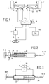
- the power steering device 4.4 'of a steering axle of a motor vehicle includes, in addition to the organs or devices 1,2,3,5 and 6 described in the preamble to this description, first and second actuators 7,7 'acting, according to the invention, on the steering angle of the wheels 4.4 ' respectively.
- each of these 7.7 'actuators takes the form of a cylinder mounted on the wheel axle itself, between a 8.8 'fixed point of articulation on this axle, respectively, and a 9.9 'rocket operating arm 10.10 'on which the 4.4' wheel is mounted respectively.
- the 9.9 'arms are connected to the rods 11.11 'of the cylinders 7.7' respectively, by connections rigid 12.12 'respectively.
- the elongations of rods 11,11 'of the cylinders 7,7' fix the angles of turning the wheels 4,4 'respectively.
- the regulator enslaves these elongations to set values l c , l ' c corresponding to the steering angles ⁇ , ⁇ ' sought for the wheels 4,4 '.
- these steering angles ⁇ , ⁇ ′ may be equal to the setpoint angle ⁇ c requested by the driver, or different from this setpoint angle.
- Control is ensured by an order appropriate energy E, E 'delivered to the cylinders 7,7' to operate the rods 11.11 ′ respectively, this energy being drawn from an energy source 14 on board the vehicle.
- the regulator is duly programmed to carry out the calculations required to assess these quantities energy E, E 'as well as the formation of the signal control of the force variator 5 acting on the shaft 6 of the steering wheel, as we saw above in the preamble to the present description. He can use to do this various parameters representative of the state of the vehicle or environment, such as vehicle speed, load of this vehicle, the torque exerted by the driver on the steering wheel, the force of the side wind, etc., these parameters being known to the regulator through appropriate sensors, globally symbolized by the line 15 in Figure 1.
- the energy source 14 used for powering the actuators is a source of energy electric such as an alternator driven by the engine vehicle thermal, assisted by a battery in case engine shutdown or alternator failure.
- the elongation of the cylinder rods is therefore controlled using energy drawn from this source.
- the jack of Figure 2 includes a screw 16 rotated around its axis by a motor electric 17 controlled by regulator 3. Rotation of the screw 16 controls the translation on the screw of a nut 18 secured to a sleeve 19 constituting the "rod" of the jack, means (not shown) then preventing the rotation of the sleeve by the screw.
- the cylinder of Figure 3 is electro-hydraulic and includes a motor 20 for driving a pump 21 suitable for circulating, in one direction or the other, a hydraulic fluid between the two chambers 22 and 23 of the actuator proper, so as to vary the elongation of the rod 24 of the jack.
- the invention is not limited to the mode described and depicted as an example. This is how the invention finds obviously application to a vehicle with more than one steering axle, or to a weight vehicle trailer heavy for example, comprising such a steering axle.
Abstract
Description
La présente invention est relative à un dispositif de servodirection de véhicule automobile, pour commander l'angle de braquage des roues gauche et droite d'au moins un essieu directeur dudit véhicule et, plus particulièrement, à un tel dispositif comprenant a) un organe de commande manuelle d'un générateur d'une valeur de consigne pour ledit angle de braquage, b) des moyens de braquage desdites roues, et c) des moyens de régulation sensibles à ladite valeur de consigne pour commander lesdits moyens de braquage de manière que les angles de braquage réels des roues soient liés à ladite valeur de consigne.The present invention relates to a device motor vehicle power steering, to control the steering angle of the left and right wheels of at least a steering axle of said vehicle and, more particularly, to such a device comprising a) a control member manual generation of a setpoint for said turning angle, b) turning means said wheels, and c) sensitive regulation means at said set value for controlling said means steering angle so that the actual steering angles wheels are linked to said set value.
On connaít de tels dispositifs notamment de
FR-A-2 744 089 et FR-A-2 745 256. Comme représenté à la
figure 1 du dessin annexé, ceux-ci comprennent un volant
constituant un organe de commande manuelle d'un
générateur 2 d'une valeur de consigne pour l'angle de
braquage des roues du véhicule. Cette valeur est
déterminée par le conducteur du véhicule, qui fait
tourner le volant 1. Le générateur 2 peut être constitué
par un capteur de position, de tout type connu, propre à
former un signal représentatif de la position angulaire
du volant.We know such devices including
FR-A-2 744 089 and FR-A-2 745 256. As shown in the
Figure 1 of the accompanying drawing, these include a steering wheel
constituting a manual control member of a
Ce signal est fourni à un régulateur 3 qui tire de
ce signal une valeur de consigne αc de l'angle de braquage
demandé par le conducteur. Le régulateur reçoit également
un signal représentatif de l'angle de braquage réel des
roues gauche et droite 4,4' respectivement, d'un essieu
directeur de véhicule automobile. Le régulateur 3 compare
les valeurs réelle et de consigne de l'angle de braquage
et commande un mécanisme d'actionnement agissant sur
l'orientation des roues 4,4' de manière que l'angle de
braquage réel de ces roues coïncide avec l'angle de
consigne αc demandé par le conducteur du véhicule.This signal is supplied to a
Le régulateur 3 commande aussi, selon FR-A-2 745 256, un
variateur d'effort 5 agissant sur l'arbre 6 du volant 1
pour que le conducteur retrouve, sur ce volant, les
forces de frottement et de rappel qu'il éprouve lorsqu'il
manoeuvre le volant d'un dispositif de direction
classique, ces forces ne "remontant" plus sur le volant
du dispositif de la figure 1, mécaniquement découplé des
roues 4,4' et des moyens utilisés pour les manoeuvrer.According to FR-A-2 745 256, the
Les dispositifs de servodirection du type décrit ci-dessus présentent de nombreux avantages et leur avenir est donc prometteur : suppression de la colonne de direction, source de blessures graves en cas d'accident, élimination des remontées de vibrations dans cette colonne, diminution possible du diamètre du volant pour les véhicules poids lourds, les autocars et les autobus, avec pour conséquence une amélioration du confort de conduite, possibilité de variation du rapport de démultiplication angle volant/angle de braquage, possibilité de superposition de corrections automatiques du braquage demandé par le conducteur, etc., etc.Power steering devices of the type described above have many advantages and their future is therefore promising: deletion of the column steering, source of serious injury in the event of an accident, elimination of rising vibrations in this column, possible reduction of the flywheel diameter for heavy goods vehicles, coaches and buses, resulting in improved comfort driving, possibility of variation of the reduction in steering wheel angle / steering angle, possibility overlapping automatic steering corrections requested by driver, etc., etc.
Les dispositifs décrits dans les brevets précités présentent cependant des inconvénients. C'est ainsi que le dispositif de servodirection à moteur électrique et crémaillère de FR-A-2 745 256 peut difficilement délivrer un couple suffisant, notamment sur un véhicule poids lourd, sauf à utiliser un moteur électrique très encombrant. Celui décrit dans FR-A-2 744 089 comprend, en parallèle avec un tel mécanisme à moteur électrique et crémaillère, un servomoteur hydraulique comprenant un vérin, des vannes et un réservoir de liquide hydraulique, raccordés par des conduits. Un tel dispositif, complexe, est d'installation et d'entretien coûteux, du fait des purges et remplissages qu'il implique, et de fiabilité douteuse du fait des fuites toujours possibles. En outre, dans le cas du dispositif décrit dans FR-A-2 745 256 comme dans celui décrit FR-A-2 744 089, une crémaillère couple les déplacements angulaires des roues gauche et droite de l'essieu directeur commandé, cette crémaillère encombrant l'espace situé entre ces deux roues.The devices described in the aforementioned patents have drawbacks, however. Therefore the power-assisted power steering device and FR-A-2 745 256 rack can hardly deliver sufficient torque, especially on a heavy vehicle heavy, except when using a very electric motor bulky. The one described in FR-A-2 744 089 includes, in parallel with such an electric motor mechanism and rack, a hydraulic servomotor comprising a cylinder, valves and a hydraulic fluid tank, connected by conduits. Such a complex device is costly to install and maintain due to purges and refills it involves, and reliability doubtful because of the always possible leaks. In addition, in the case of the device described in FR-A-2 745 256 as in that described FR-A-2 744 089, a rack couples the angular displacements of the left wheels and right of the driven steering axle, this rack cluttering the space between these two wheels.
La présente invention a donc pour but de réaliser un dispositif de servodirection du type décrit en préambule de la présente description, qui ne présente pas les inconvénients mentionnés ci-dessus des dispositifs de la technique antérieure.The present invention therefore aims to achieve a power steering device of the type described in the preamble of this description, which does not present the above mentioned disadvantages of the devices of the prior art.
On atteint ce but de l'invention, ainsi que d'autres qui apparaítront dans la suite de la présente description, avec un dispositif de servodirection de véhicule automobile, pour commander l'angle de braquage des roues gauche et droite d'au moins un essieu directeur dudit véhicule, ce dispositif comprenant a) un organe de commande manuelle d'un générateur de valeur de consigne pour ledit angle de braquage, b) des moyens de braquage desdites roues, et c) des moyens de régulation sensibles à ladite valeur de consigne pour commander lesdits moyens de braquage de manière que les angles de braquage réels des roues soient liés à ladite valeur de consigne, ce dispositif étant remarquable en ce que lesdits moyens de braquage sont constitués par des premier et deuxième actionneurs agissant sur les angles de braquage desdites roues gauche et droite respectivement, dudit essieu, lesdits actionneurs étant commandés indépendamment l'un de l'autre par lesdits moyens de régulation.This object of the invention is achieved, as well as other which will appear later in this description, with a power steering device motor vehicle, to control the steering angle left and right wheels of at least one steering axle of said vehicle, this device comprising a) a member for manual control of a setpoint generator for said turning angle, b) turning means said wheels, and c) sensitive regulation means at said set value for controlling said means steering angle so that the actual steering angles wheels are linked to said setpoint, this device being remarkable in that said means of deflection consist of first and second actuators acting on the turning angles of said left and right wheels respectively, of said axle, said actuators being independently controlled one on the other by said regulation means.
Comme on le verra plus loin, l'affectation d'un actionneur particulier à chacune des roues de l'essieu permet de supprimer tout couplage mécanique entre les deux roues, et donc de libérer une partie de l'espace qui les sépare au profit du moteur du véhicule, par exemple. Le pilotage séparé des angles de braquage des deux roues permet, par ailleurs, de respecter parfaitement l'épure de Jeantaud, ce qui améliore la tenue de route du véhicule dans les virages tout en diminuant l'usure des pneumatiques de ce véhicule, avec pour conséquence l'allongement de leur durée de vie utile.As will be seen below, the assignment of a actuator specific to each of the axle wheels eliminates any mechanical coupling between the two wheels, and therefore free up part of the space that separates them for the benefit of the vehicle engine, for example. Separate steering of the steering angles of the two wheels allows, moreover, to perfectly respect the sketch Jeantaud, which improves the road handling of the vehicle when cornering while reducing wear on tires of this vehicle, with the consequence extending their useful life.
D'autres caractéristiques et avantages du dispositif selon la présente invention apparaítront à la lecture de la description qui va suivre et à l'examen du dessin annexé dans lequel :
- la figure 1 est une représentation schématique du dispositif de servodirection suivant l'invention, déjà partiellement décrit en préambule de la présente description, et
- les figures 2 et 3 sont des représentations schématiques d'actionneurs préférés, pour l'équipement du dispositif de la figure 1.
- FIG. 1 is a schematic representation of the power steering device according to the invention, already partially described in the preamble to this description, and
- Figures 2 and 3 are schematic representations of preferred actuators, for the equipment of the device of Figure 1.
On se réfère à la figure 1 du dessin annexé où il
apparaít que le dispositif de servodirection des roues
4,4' d'un essieu directeur d'un véhicule automobile
comprend, outre les organes ou appareils 1,2,3,5 et 6
décrits en préambule de la présente description, des
premier et deuxième actionneurs 7,7' agissant, suivant
l'invention, sur l'angle de braquage des roues 4,4'
respectivement. Comme cela apparaít aussi sur la figure
1, chacun de ces actionneurs 7,7' prend la forme d'un
vérin monté sur l'essieu de roues lui-même, entre un
point d'articulation fixe 8,8' sur cet essieu,
respectivement, et un bras 9,9' de manoeuvre d'une fusée
10,10' sur laquelle est montée la roue 4,4'
respectivement. Les bras 9,9' sont reliés aux tiges
11,11' des vérins 7,7' respectivement, par des liaison
rigides 12,12' respectivement. Ainsi, les élongations des
tiges 11,11' des vérins 7,7' fixent les angles de
braquage des roues 4,4' respectivement.We refer to Figure 1 of the accompanying drawing where it
appears that the power steering device
4.4 'of a steering axle of a motor vehicle
includes, in addition to the organs or
Des capteurs de position 13,13' sensibles à
l'élongation des tiges des vérins 7,7' respectivement,
fournissent au régulateur 3 des signaux 1,1'
représentatifs de ces élongations. Le régulateur assure
l'asservissement de ces élongations à des valeurs de
consigne lc, l'c correspondant aux angles de braquage α,α'
recherchés pour les roues 4,4'.
Suivant la présente invention, comme on le verra plus loin, ces angles de braquage α, α' peuvent être égaux à l'angle de consigne αc demandé par le conducteur, ou différents de cet angle de consigne.According to the present invention, as will be seen below, these steering angles α, α ′ may be equal to the setpoint angle α c requested by the driver, or different from this setpoint angle.
L'asservissement est assuré par une commande
appropriée de l'énergie E,E' délivrée aux vérins 7,7'
pour manoeuvrer les tiges 11,11' respectivement, cette
énergie étant prélevée sur une source d'énergie 14
embarquée dans le véhicule.Control is ensured by an order
appropriate energy E, E 'delivered to the
Le régulateur est dûment programmé pour procéder aux
calculs nécessaires à l'évaluation de ces quantités
d'énergie E,E' ainsi qu'à la formation du signal de
commande du variateur d'effort 5 agissant sur l'arbre 6
du volant, comme on l'a vu plus haut en préambule de la
présente description. Il peut utiliser pour ce faire
divers paramètres représentatifs de l'état du véhicule ou
de son environnement, tels que la vitesse du véhicule, la
charge de ce véhicule, le couple exercé par le conducteur
sur le volant, la force du vent latéral, etc., ces
paramètres étant connus du régulateur grâce à des
capteurs appropriés, symbolisés globalement par la ligne
15 sur la figure 1.The regulator is duly programmed to carry out the
calculations required to assess these quantities
energy E, E 'as well as the formation of the signal
control of the force variator 5 acting on the shaft 6
of the steering wheel, as we saw above in the preamble to the
present description. He can use to do this
various parameters representative of the state of the vehicle or
environment, such as vehicle speed,
load of this vehicle, the torque exerted by the driver
on the steering wheel, the force of the side wind, etc., these
parameters being known to the regulator through
appropriate sensors, globally symbolized by the
Suivant un mode de réalisation préféré de
l'invention, la source d'énergie 14 utilisée pour
alimenter les actionneurs est une source d'énergie
électrique telle qu'un alternateur entraíné par le moteur
thermique du véhicule, assisté par une batterie en cas
d'arrêt du moteur ou de défaillance de l'alternateur.
L'élongation des tiges des vérins est donc commandée à
l'aide d'une énergie tirée de cette source.According to a preferred embodiment of
the invention, the
On a représenté schématiquement aux figures 2 et 3
des vérins utilisables dans le dispositif suivant
l'invention. Le vérin de la figure 2 comprend une vis 16
mise en rotation autour de son axe par un moteur
électrique 17 commandé par le régulateur 3. La rotation
de la vis 16 commande la translation sur la vis d'un
écrou 18 solidaire d'un manchon 19 constituant la "tige"
du vérin, des moyens (non représentés) empêchant alors la
mise en rotation du manchon par la vis.Schematically shown in Figures 2 and 3
cylinders usable in the following device
the invention. The jack of Figure 2 includes a
Le vérin de la figure 3 est électro-hydraulique et
comprend un moteur 20 d'entraínement d'une pompe 21
propre à faire circuler, dans un sens ou dans l'autre, un
liquide hydraulique entre les deux chambres 22 et 23 du
vérin proprement dit, de manière à faire varier
l'élongation de la tige 24 du vérin.The cylinder of Figure 3 is electro-hydraulic and
includes a
Il apparaít maintenant que, dans sa structure comme dans son fonctionnement, le dispositif de servodirection suivant l'invention décrit ci-dessus permet bien d'obtenir les avantages annoncés. C'est ainsi que :
- l'association d'un actionneur de braquage à chaque roue dégage un espace libre entre ceux-ci, autour de l'axe longitudinal du véhicule. Cet espace peut être occupé par au moins une partie du moteur du véhicule, dont le centre de gravité se trouve ainsi avantageusement abaissé.
- le pilotage séparé des angles de braquage α,α' des
roues 4, 4' respectivement par le
régulateur 3 permet de respecter parfaitement l'épure de Jeantaud. On sait que cette épure établit que les angles de braquage des deux roues d'un même essieu directeur doivent être légèrement différents pour assurer la convergence des axes des roues sur le centre de rotation du véhicule, quand celui-ci circule dans des virages. Lerégulateur 3 du dispositif suivant l'invention peut être dûment programmé pour, dans une telle situation, régler les angles α et α' à des valeurs différentes choisies pour respecter parfaitement la condition explicitée ci-dessus. La tenue de route du véhicule en est améliorée et la durée de vie des pneumatiques de ce véhicule accrue. - le montage des actionneurs sur l'essieu lui-même supprime le braquage induit par des variations du débattement entre la masse suspendue et la masse non suspendue, au niveau de chaque roue.
- l'indépendance des angles de braquage des deux roues permet d'adapter ces angles à des conditions de roulement différentes pour les deux roues, ou à des stratégies particulières de freinage du véhicule, de circulation en virage du véhicule, ou encore de renforcement de la stabilité du véhicule en présence d'un coup de vent latéral, par exemple.
- la présence de deux actionneurs permet de conserver au véhicule une certaine directibilité en cas de panne de l'un d'eux.
- the association of a steering actuator with each wheel creates a free space between them, around the longitudinal axis of the vehicle. This space can be occupied by at least part of the vehicle engine, the center of gravity of which is thus advantageously lowered.
- the separate steering of the steering angles α, α ′ of the wheels 4, 4 ′ respectively by the
regulator 3 makes it possible to perfectly respect Jeantaud's outline. It is known that this sketch establishes that the turning angles of the two wheels of the same steering axle must be slightly different to ensure the convergence of the axes of the wheels on the center of rotation of the vehicle, when it is traveling in turns. Theregulator 3 of the device according to the invention can be duly programmed to, in such a situation, adjust the angles α and α ′ to different values chosen to perfectly respect the condition explained above. The handling of the vehicle is improved and the life of the tires of this vehicle increased. - mounting the actuators on the axle itself eliminates the deflection induced by variations in the travel between the suspended mass and the unsprung mass, at the level of each wheel.
- the independence of the steering angles of the two wheels makes it possible to adapt these angles to different rolling conditions for the two wheels, or to specific strategies for braking the vehicle, for turning the vehicle in turns, or even for strengthening the vehicle stability in the presence of a side wind gust, for example.
- the presence of two actuators allows the vehicle to maintain a certain directibility in the event of a failure of one of them.
Bien entendu, l'invention n'est pas limitée au mode de réalisation décrit et représenté qui n'a été donné qu'à titre d'exemple. C'est ainsi que l'invention trouve évidemment application à un véhicule comptant plus d'un essieu directeur, ou à une remorque de véhicule poids lourd par exemple, comportant un tel essieu directeur.Of course, the invention is not limited to the mode described and depicted as an example. This is how the invention finds obviously application to a vehicle with more than one steering axle, or to a weight vehicle trailer heavy for example, comprising such a steering axle.
Claims (5)
Applications Claiming Priority (2)
| Application Number | Priority Date | Filing Date | Title |
|---|---|---|---|
| FR0001417 | 2000-02-04 | ||
| FR0001417A FR2804647B1 (en) | 2000-02-04 | 2000-02-04 | MOTOR VEHICLE SERVO DIRECTION DEVICE |
Publications (1)
| Publication Number | Publication Date |
|---|---|
| EP1122150A1 true EP1122150A1 (en) | 2001-08-08 |
Family
ID=8846661
Family Applications (1)
| Application Number | Title | Priority Date | Filing Date |
|---|---|---|---|
| EP01400263A Withdrawn EP1122150A1 (en) | 2000-02-04 | 2001-02-02 | Motor vehicle power steering device |
Country Status (2)
| Country | Link |
|---|---|
| EP (1) | EP1122150A1 (en) |
| FR (1) | FR2804647B1 (en) |
Cited By (5)
| Publication number | Priority date | Publication date | Assignee | Title |
|---|---|---|---|---|
| EP1314628A1 (en) * | 2001-11-23 | 2003-05-28 | Conception et Développement Michelin S.A. | Electric steering for a vehicle with triple redundance |
| DE10211809A1 (en) * | 2002-03-16 | 2003-05-28 | Zf Lenksysteme Gmbh | Power steering arrangement, especially steer-by-wire, has non-self-limiting steering modules; imaginary extension of steering axle intercepts ground in front of wheel contact point |
| FR2879153A1 (en) * | 2004-12-13 | 2006-06-16 | Renault Sas | Mac Pherson steering assembly for vehicle, has connecting rod and rotating part assembled with each other by threaded connection so that rod is displaced in translation with respect to actuator along longitudinal axis of rod |
| FR2909064A1 (en) * | 2006-11-28 | 2008-05-30 | Renault Sas | Steering wheel controlling method for e.g. two-wheel vehicle, involves detecting driving situation by detecting whether longitudinal speed is lower than threshold speed, and applying Jeantaud angulation to steering wheels |
| FR2928126A1 (en) | 2008-02-29 | 2009-09-04 | Renault Sas | Electronically controlled steering system e.g. steer-by-wire steering system, for motor vehicle, has proportional corrector generating torque from speed set point generated by derivative block and integral proportional corrector |
Families Citing this family (1)
| Publication number | Priority date | Publication date | Assignee | Title |
|---|---|---|---|---|
| FR2842490B1 (en) | 2002-07-18 | 2004-12-24 | Renault Vehicules Ind | VEHICLE STEERING SYSTEM |
Citations (1)
| Publication number | Priority date | Publication date | Assignee | Title |
|---|---|---|---|---|
| WO1996039321A1 (en) * | 1995-06-06 | 1996-12-12 | University Of Arkansas, N.A. | Lever steering system |
Family Cites Families (2)
| Publication number | Priority date | Publication date | Assignee | Title |
|---|---|---|---|---|
| DE19603270C1 (en) | 1996-01-30 | 1997-07-10 | Daimler Benz Ag | Hydraulic power steering for motor vehicles |
| DE19607028C1 (en) | 1996-02-24 | 1997-08-21 | Daimler Benz Ag | Steering for non-track-bound vehicles |
-
2000
- 2000-02-04 FR FR0001417A patent/FR2804647B1/en not_active Expired - Fee Related
-
2001
- 2001-02-02 EP EP01400263A patent/EP1122150A1/en not_active Withdrawn
Patent Citations (1)
| Publication number | Priority date | Publication date | Assignee | Title |
|---|---|---|---|---|
| WO1996039321A1 (en) * | 1995-06-06 | 1996-12-12 | University Of Arkansas, N.A. | Lever steering system |
Cited By (7)
| Publication number | Priority date | Publication date | Assignee | Title |
|---|---|---|---|---|
| EP1314628A1 (en) * | 2001-11-23 | 2003-05-28 | Conception et Développement Michelin S.A. | Electric steering for a vehicle with triple redundance |
| FR2832685A1 (en) * | 2001-11-23 | 2003-05-30 | Conception & Dev Michelin Sa | ELECTRIC STEERING FOR VEHICLE, TRIPLE REDUNDANCY |
| US6820715B2 (en) | 2001-11-23 | 2004-11-23 | Conception et Développement Michelin S.A. | Electrical steering for vehicle, with triple redundancy |
| DE10211809A1 (en) * | 2002-03-16 | 2003-05-28 | Zf Lenksysteme Gmbh | Power steering arrangement, especially steer-by-wire, has non-self-limiting steering modules; imaginary extension of steering axle intercepts ground in front of wheel contact point |
| FR2879153A1 (en) * | 2004-12-13 | 2006-06-16 | Renault Sas | Mac Pherson steering assembly for vehicle, has connecting rod and rotating part assembled with each other by threaded connection so that rod is displaced in translation with respect to actuator along longitudinal axis of rod |
| FR2909064A1 (en) * | 2006-11-28 | 2008-05-30 | Renault Sas | Steering wheel controlling method for e.g. two-wheel vehicle, involves detecting driving situation by detecting whether longitudinal speed is lower than threshold speed, and applying Jeantaud angulation to steering wheels |
| FR2928126A1 (en) | 2008-02-29 | 2009-09-04 | Renault Sas | Electronically controlled steering system e.g. steer-by-wire steering system, for motor vehicle, has proportional corrector generating torque from speed set point generated by derivative block and integral proportional corrector |
Also Published As
| Publication number | Publication date |
|---|---|
| FR2804647B1 (en) | 2002-06-07 |
| FR2804647A1 (en) | 2001-08-10 |
Similar Documents
| Publication | Publication Date | Title |
|---|---|---|
| FR2772331A1 (en) | STEERING FOR A VEHICLE | |
| JP4176306B2 (en) | Inclined vehicle | |
| EP0783414B1 (en) | A vehicle suspension system for a steerable wheel | |
| RU2205122C2 (en) | Vehicle with adjustable angle of tilting | |
| US6386553B2 (en) | Vehicle wheel suspension arrangement | |
| EP1428740B1 (en) | Vehicle steering system with an emergency operating mode in the event of a failure of a wheel steering actuator | |
| FR2741028A1 (en) | ASSISTED STEERING FOR MOTOR VEHICLES | |
| FR2721572A1 (en) | Device for controlling a reaction force to a hydraulic power steering manual actuating element, in particular for a motor vehicle. | |
| FR2773763A1 (en) | STEERING SYSTEM | |
| CN113165694B (en) | Self-balancing tilting vehicle with electric tilting member | |
| FR2660258A1 (en) | ELECTRIC VEHICLE WITH SPEED ADJUSTABLE WITH SAFETY. | |
| FR2744089A1 (en) | HYDRAULIC SERVODIRECTION FOR MOTOR VEHICLES | |
| FR2949421A1 (en) | TRACK CONTROL DEVICE FOR NARROW ELECTRIC MOTORIZED VEHICLE AND INCLINED TILT | |
| FR2832682A1 (en) | Steering control for vehicle uses electrical linkage, with angle and force sensors detecting movement of two-handled steering wheel | |
| EP1122150A1 (en) | Motor vehicle power steering device | |
| FR2606711A1 (en) | Air spring arrangement for double axled vehicles | |
| KR101806682B1 (en) | Adaptive Front Steering system for vehicle | |
| EP1234746B1 (en) | Electric power steering assembly for a motor vehicle and associated control method | |
| FR2812264A1 (en) | Individual power steering for motor vehicle wheels has each steering motor separately connected to control circuit | |
| FR2914260A1 (en) | Four wheeled motor vehicle e.g. industrial vehicle, for e.g. building site, has electronic control unit including auxiliary units decelerating torques to be applied on wheels found at interior or exterior of turning via units, respectively | |
| EP0865944A1 (en) | Anti-roll device for a motor vehicle | |
| FR2867437A1 (en) | ELECTRIC MOTOR VEHICLE STEERING ASSISTANCE DEVICE, STEERING ASSEMBLY PROVIDED WITH SUCH A DEVICE AND MOTOR VEHICLE EQUIPPED WITH SUCH AN ASSEMBLY | |
| EP0439978B1 (en) | Motor car rear axle having a transverse mounting member pivotable with respect to the chassis | |
| JPS62214059A (en) | Automobile steering device | |
| WO2002000487A1 (en) | Motor vehicle power steering device |
Legal Events
| Date | Code | Title | Description |
|---|---|---|---|
| PUAI | Public reference made under article 153(3) epc to a published international application that has entered the european phase |
Free format text: ORIGINAL CODE: 0009012 |
|
| AK | Designated contracting states |
Kind code of ref document: A1 Designated state(s): AT BE CH CY DE DK ES FI FR GB GR IE IT LI LU MC NL PT SE TR |
|
| AX | Request for extension of the european patent |
Free format text: AL;LT;LV;MK;RO;SI |
|
| AKX | Designation fees paid |
Free format text: AT BE CH CY DE DK ES FI FR GB GR IE IT LI LU MC NL PT SE TR |
|
| 17P | Request for examination filed |
Effective date: 20020218 |
|
| RAP1 | Party data changed (applicant data changed or rights of an application transferred) |
Owner name: RENAULT VEHICULES INDUSTRIELS |
|
| 17Q | First examination report despatched |
Effective date: 20040714 |
|
| STAA | Information on the status of an ep patent application or granted ep patent |
Free format text: STATUS: THE APPLICATION IS DEEMED TO BE WITHDRAWN |
|
| 18D | Application deemed to be withdrawn |
Effective date: 20060131 |