EP1122127A2 - Optical axis adjusting apparatus in head light for automobile - Google Patents
Optical axis adjusting apparatus in head light for automobile Download PDFInfo
- Publication number
- EP1122127A2 EP1122127A2 EP01102266A EP01102266A EP1122127A2 EP 1122127 A2 EP1122127 A2 EP 1122127A2 EP 01102266 A EP01102266 A EP 01102266A EP 01102266 A EP01102266 A EP 01102266A EP 1122127 A2 EP1122127 A2 EP 1122127A2
- Authority
- EP
- European Patent Office
- Prior art keywords
- case
- optical axis
- adjusting apparatus
- motor
- axis adjusting
- Prior art date
- Legal status (The legal status is an assumption and is not a legal conclusion. Google has not performed a legal analysis and makes no representation as to the accuracy of the status listed.)
- Granted
Links
Images


Classifications
-
- B—PERFORMING OPERATIONS; TRANSPORTING
- B60—VEHICLES IN GENERAL
- B60Q—ARRANGEMENT OF SIGNALLING OR LIGHTING DEVICES, THE MOUNTING OR SUPPORTING THEREOF OR CIRCUITS THEREFOR, FOR VEHICLES IN GENERAL
- B60Q1/00—Arrangement of optical signalling or lighting devices, the mounting or supporting thereof or circuits therefor
- B60Q1/02—Arrangement of optical signalling or lighting devices, the mounting or supporting thereof or circuits therefor the devices being primarily intended to illuminate the way ahead or to illuminate other areas of way or environments
- B60Q1/04—Arrangement of optical signalling or lighting devices, the mounting or supporting thereof or circuits therefor the devices being primarily intended to illuminate the way ahead or to illuminate other areas of way or environments the devices being headlights
- B60Q1/06—Arrangement of optical signalling or lighting devices, the mounting or supporting thereof or circuits therefor the devices being primarily intended to illuminate the way ahead or to illuminate other areas of way or environments the devices being headlights adjustable, e.g. remotely-controlled from inside vehicle
- B60Q1/076—Arrangement of optical signalling or lighting devices, the mounting or supporting thereof or circuits therefor the devices being primarily intended to illuminate the way ahead or to illuminate other areas of way or environments the devices being headlights adjustable, e.g. remotely-controlled from inside vehicle by electrical means including means to transmit the movements, e.g. shafts or joints
-
- H—ELECTRICITY
- H02—GENERATION; CONVERSION OR DISTRIBUTION OF ELECTRIC POWER
- H02K—DYNAMO-ELECTRIC MACHINES
- H02K7/00—Arrangements for handling mechanical energy structurally associated with dynamo-electric machines, e.g. structural association with mechanical driving motors or auxiliary dynamo-electric machines
- H02K7/10—Structural association with clutches, brakes, gears, pulleys or mechanical starters
- H02K7/116—Structural association with clutches, brakes, gears, pulleys or mechanical starters with gears
- H02K7/1163—Structural association with clutches, brakes, gears, pulleys or mechanical starters with gears where at least two gears have non-parallel axes without having orbital motion
- H02K7/1166—Structural association with clutches, brakes, gears, pulleys or mechanical starters with gears where at least two gears have non-parallel axes without having orbital motion comprising worm and worm-wheel
-
- H—ELECTRICITY
- H02—GENERATION; CONVERSION OR DISTRIBUTION OF ELECTRIC POWER
- H02K—DYNAMO-ELECTRIC MACHINES
- H02K11/00—Structural association of dynamo-electric machines with electric components or with devices for shielding, monitoring or protection
-
- H—ELECTRICITY
- H02—GENERATION; CONVERSION OR DISTRIBUTION OF ELECTRIC POWER
- H02K—DYNAMO-ELECTRIC MACHINES
- H02K5/00—Casings; Enclosures; Supports
- H02K5/04—Casings or enclosures characterised by the shape, form or construction thereof
- H02K5/22—Auxiliary parts of casings not covered by groups H02K5/06-H02K5/20, e.g. shaped to form connection boxes or terminal boxes
- H02K5/225—Terminal boxes or connection arrangements
Definitions
- the present invention relates to an optical axis adjusting apparatus in a head light for an automobile, for example, a head lamp, a fog lamp or the like in an automobile, and more particularly to an optical axis adjusting apparatus in a head light for an automobile in which a heat radiating performance of a motor can be improved, an assembling property can be improved and a compact size can be achieved.
- an optical axis adjusting apparatus in this kind of head light for the automobile for example, there is a structure described in Japanese Patent Application Laid-Open No. 8-164789. A description will be given below of an optical axis adjusting apparatus in a head light for an automobile with reference to Figs. 12 to 14.
- reference symbol L denotes a head light for an automobile.
- the head light L for the automobile is structured such that a lamp chamber 3 is defined by a lamp housing 1 and a lens 2.
- a light source bulb (not shown) is arranged within the lamp chamber 2, and a reflector 4 reflecting a light beam output from the light source bulb to a side of the lens 2 is arranged so as to freely tilt.
- the structure is made such that an optical axis adjusting apparatus 5 is arranged between the lamp housing 1 and the reflector 4. Then, the reflector 4 is tilted in accordance with an operation of the optical axis adjusting apparatus 5, whereby an optical axis is adjusted.
- the optical axis adjusting apparatus 5 is provided with a case 50, a motor 51 and a speed reduction mechanism 52 which are received within the case 50, and an extendable/retractable rod 53 extending/retracting via the speed reduction mechanism 52 due to a driving operation of the motor 51 so as to tilt the reflector 4.
- the optical axis adjusting apparatus 5 in the conventional head light for the automobile mentioned above is structured such that the motor 51 is received within the case 50 in a substantially closed state, the case 50 is filled with heat of the motor 51, so that there is a problem concerning a heat radiating performance of the motor.
- the present invention is characterized in that a case is separable into two portions, and an opening portion to which a motor is inserted and an insertion hole to which an extendable/retractable rod is inserted so as to freely oscillate are provided in the same direction.
- an optical axis adjusting apparatus of a head light for an automobile in accordance with the present invention since an outer portion and an inner portion of the case are communicated with each other by the opening portion and the insertion hole provided in the case, heat of the motor within the case is discharged to an external portion via the opening portion and the insertion hole, so that a heat radiating performance of the motor can be improved. Further, since shapes of the opening portion and the insertion hole substantially coincide with outer shapes of the motor and the extendable/retractable rod, the opening portion and the insertion hole serve as a guide at a time of assembling a first case, so that an assembling property can be improved.
- the motor is inserted into the opening portion, whereby it is possible to reduce a width in an extending/retracting direction of the extendable/retractable rod at a degree corresponding to a size between an outer surface of the case and the motor in comparison with the structure in which the motor is received within the case in a substantially sealed state, it is possible to achieve a compact size.
- Figs. 1 to 7 show a first embodiment of the optical axis adjusting apparatus in the head light for the automobile in accordance with the present invention.
- the same reference numerals denote the same elements as those in Figs. 12 to 14.
- reference numeral 6 denotes an optical axis adjusting apparatus in accordance with the present invention.
- the optical axis adjusting apparatus 6 is constituted by two separable cases 60 and 61, a motor 62, a speed reduction mechanism 63 and an extendable/retractable rod 64.
- a first case 60 of two separable cases is, for example, made of resin as shown in Figs. 1, 4 and 6, and is formed in a shape in which a front portion is closed and a rear portion is opened.
- the motor 62 is provided with a rectangular opening portion 600 to which the motor 62 is inserted and which substantially coincides with an outer shape of the motor 62, and a circular insertion hole 601 to which the extendable/retractable rod 64 is inserted so as to freely oscillate and which substantially coincides with an outer shape of the extendable/retractable rod 64.
- These opening portion 600 and the insertion hole 601 are provided in the same direction, that is, in an extending/retracting direction of the extendable/retractable rod 64.
- two recess portions 602 for preventing the extendable/retractable rod 64 from rotating are provided in the insertion hole 601. Further, two circular through holes 603 are respectively provided in this first case 60. Further, a holder portion 604 for holding the speed reduction mechanism 63 is integrally protruded rearward in this first case 60.
- the other case 61 among the two separable cases is, for example, made of resin as shown in Figs. 1 to 5 and 7, and is formed in a shape in which a front portion is opened and a rear portion is closed.
- a motor holder portion for holding the motor 62 and speed reduction mechanism holder portions 611 and 612 for holding the speed reduction mechanism 63 are respectively protruded forward in the other case 61 in an integral manner.
- the speed reduction mechanism holder portion is constituted by a first speed reduction mechanism holder portion 611 having a large diameter and formed in a cylindrical shape, and a second speed reduction mechanism holder portion 611 having a small diameter and formed in a cylindrical shape.
- a connector portion 613 is integrally protruded rearward in the other case 61.
- Three terminals 614 are provided in this connector portion 613 in accordance with an insert molding.
- two circular through holes 615 are respectively provided in the other case 61 in correspondence to the through hole 603 in the first case 60.
- An electric circuit board 620 is mounted to the motor 62 and is electrically connected thereto.
- the electric circuit board 620 is constituted by a printed circuit board (PCB) or the like on which a control circuit and the like are printed and wired.
- a position sensor 621 such as a potentiometer or the like is mounted on the electric circuit board 620.
- a rotation of the motor 62 is detected by the position sensor 621, and the rotation of the motor 62 is controlled by the control circuit.
- the speed reduction mechanism 63 is, as shown in Figs. 1 and 3 to 5, constituted by a worm 630 fixed to a rotary shaft of the motor 62, a worm wheel 631 engaged with the worm 630, an idle gear 632 integrally formed with the worm wheel 631, and an output gear 633 engaged with the idle gear 632.
- a female feeding screw portion 634 is provided in a center of the output gear 633.
- circular recess portions 635 and 636 are provided in one surface sides of the output gear 633 and the idle gear 632.
- the extendable/retractable rod 64 is, as shown in Figs. 1 and 3 to 5, constituted by a spherical portion 640 disposed at one end portion, a male feeding screw portion 641 at another end portion, and two convex portions 642 for preventing another end portion from rotating.
- the male feeding screw portion 641 is screwed into the female feeding screw portion 634 of the output gear 633.
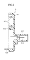
- the electric circuit board 620, the motor 62, the speed reduction mechanism 63 and the extendable/retractable rod 64 are assembled in the other case 61 shown in Fig. 2 (refer to Fig. 3). That is, the electric circuit board 620 is fixed to the other case 61.
- the motor 62 is held by the motor holder portion 610.
- the cylindrical first speed reduction mechanism holder portion 611 and second speed reduction mechanism holder 612 are set to the circular recess portions 635 and 636 in one surface sides of the output gear 633 and the idle gear 632, whereby the output gear 633 and the idle gear 632 are rotatably held in the first speed reduction mechanism holder portion 611 and the second speed reduction mechanism holder 612.
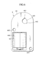
- the first case 60 is assembled in the other case 61 in which the electric circuit board 620, the motor 62, the speed reduction mechanism 63 and the extendable/retractable rod 64 are assembled (refer to Fig. 4). That is, the motor 62 is inserted into the opening portion 600, the extendable/retractable rod 64 is inserted to the insertion hole 601 so as to freely oscillate, the rotation preventing convex portion 642 is fitted to the rotation preventing recess portion 602 so as to freely oscillate, and the output gear 633 is rotatably held by the holder portion 604 together with the first speed reduction mechanism holder portion 611.
- the optical axis adjusting apparatus 6 in accordance with the present invention can be assembled.
- the optical axis adjusting apparatus 6 in accordance with the present invention is mounted to the lamp housing 1, and the spherical portion 640 of the extendable/retractable rod 64 is fitted to a spherical recess portion (not shown) of the reflector 4 (refer to Fig. 1). That is, the optical axis adjusting apparatus 6 in accordance with the present invention is arranged inside the lamp chamber 3, the connector portion 613 is inserted to a window portion 10 provided in the lamp housing 1, an O-ring 11 is interposed between the lamp housing 1 and the case 61, a screw (not shown) is inserted into the circular through holes 603 and 615, and the optical axis adjusting apparatus 6 is mounted to the lamp housing 1 by means of the screw. As a result, the optical axis adjusting apparatus 6 in accordance with the present invention is arranged between the lamp housing 1 and the reflector 4.
- the optical axis adjusting apparatus 6 in accordance with the present invention in this embodiment is structured in a manner mentioned below, a heat radiating performance of the motor 62 can be improved, an assembling property can be improved and a compact size can be achieved.
- the optical axis adjusting apparatus 6 in accordance with the present invention in this embodiment is structured such that an outer portion and an inner portion of the cases 60 and 61 are communicated with each other by the opening portion 600 and the insertion hole 601 which are provided in the first case 60, heat of the motor 62 within the cases 60 and 61 is radiated outward via the opening portion 600 and the insertion hole 601, so that a heat radiating performance of the motor 62 can be improved.
- the optical axis adjusting apparatus 6 in accordance with the present invention in this embodiment is structured such that the shapes of the opening portion 600 and the insertion hole 601 substantially coincide with the outer shapes of the motor 62 and the extendable/retractable rod 64, the opening portion 600 and the insertion hole 601 serve as a guide at a time of assembling the first case 60 in the other case 61 in which the electric circuit board 620, the motor 62, the speed reduction mechanism 63 and the extendable/retractable rod 64 are assembled, so that an assembling property can be improved.
- the optical axis adjusting apparatus 6 in accordance with the present invention in this embodiment is, as shown in Fig. 1, structured such that the motor 62 is inserted to the opening portion 600, whereby it is possible to reduce a width in an extending/retracting direction of the extendable/retractable rod 64 at a degree of a size W between the outer surface of the case 50 and the motor 62 in comparison with the structure in which the motor 62 is received within the case 50 (shown by a double-dotted chain line in Fig. 1) in a substantially sealed state, so that a compact size can be achieved.
- the optical axis adjusting apparatus 6 in this embodiment is structured such that the case is constituted by two separable cases, and the other case 62 within which the electric circuit board 620, the motor 62, the speed reduction mechanism 63 and the extendable/retractable rod 64 are assembled is assembled in the first case 60, an assembling property can be further improved.
- Figs. 8 to 11 show a second embodiment of an optical axis adjusting apparatus in a head lamp for an automobile in accordance with the present invention.
- the same reference numerals as those of Figs. 1 to 7 and Figs. 12 to 14 denote the same elements.
- An optical axis adjusting apparatus 6' in accordance with the present invention in this embodiment is, as shown in Figs. 8 to 11, such that the first case 60' is constituted by a part of the housing 1. That is, a recess portion 12 for the case is provided in a part of the lamp housing 1, and the opening portion 600, the insertion hole 601, the rotation preventing recess portion 602 and the holder portion 604 are provided in the recess portion 12.
- a seal recess portion 616 is provided in an opening end portion of the other case 61.
- the optical axis adjusting apparatus 6' is constructed by assembling the other case 61 in the first case 60' integrally formed with the lamp housing 1 with interposing an O-ring 617.
- the structure in accordance with the second embodiment can achieve the same operations and effects as those of the first embodiment mentioned above.
- the second embodiment is structured such that the first case 60' is constituted by a part of the lamp housing 1, the number of parts can be reduced.
- the other case 61 protrudes outside the lamp housing 1 and the first case 60' protrudes inside the lamp housing 1, a protruding size to the inside from the lamp housing 1 is reduced in comparison with the structure in which a whole of the optical axis adjusting apparatus is arranged inside the lamp housing 1. As a result, it is possible to reduce a depth of the head light for the automobile.
- the first case 60' is integrally formed with the lamp housing 1, however, in accordance with the present invention, the other case 60 may be integrally formed with the lamp housing 1 in a reverse manner.
- the structure is made such that the motor 62, the speed reduction mechanism 63 and the extendable/retractable rod 64 are assembled within the other case 61 and thereafter the other case 61 is assembled in the first case 60 or 60', however, in accordance with the present invention, the structure may be made such that the motor 62, the speed reduction mechanism 63 and the extendable/retractable rod 64 are assembled within the first case 60 or 60' and thereafter the first case 60 or 60' is assembled in the other case 61.
- the opening portion and the inner portion of the case are communicated with each other by the opening portion and the insertion hole provided in the case, the heat of the motor within the case is discharged to the external portion via the opening portion and the insertion hole, so that a heat radiating performance of the motor can be improved.
- the shapes of the opening portion and the insertion hole substantially coincide with the outer shapes of the motor and the extendable/retractable rod, the opening portion and the insertion hole serve as the guide at a time of assembling the first case, so that an assembling property can be improved.
- the motor is inserted into the opening portion, whereby it is possible to reduce the width in the extending/retracting direction of the extendable/retractable rod at a degree corresponding to the size between the outer surface of the case and the motor in comparison with the structure in which the motor is received within the case in a substantially sealed state, it is possible to achieve a compact size.
Abstract
Description
- The present invention relates to an optical axis adjusting apparatus in a head light for an automobile, for example, a head lamp, a fog lamp or the like in an automobile, and more particularly to an optical axis adjusting apparatus in a head light for an automobile in which a heat radiating performance of a motor can be improved, an assembling property can be improved and a compact size can be achieved.
- As an optical axis adjusting apparatus in this kind of head light for the automobile, for example, there is a structure described in Japanese Patent Application Laid-Open No. 8-164789. A description will be given below of an optical axis adjusting apparatus in a head light for an automobile with reference to Figs. 12 to 14.
- In the drawings, reference symbol L denotes a head light for an automobile. The head light L for the automobile is structured such that a
lamp chamber 3 is defined by alamp housing 1 and alens 2. A light source bulb (not shown) is arranged within thelamp chamber 2, and areflector 4 reflecting a light beam output from the light source bulb to a side of thelens 2 is arranged so as to freely tilt. The structure is made such that an opticalaxis adjusting apparatus 5 is arranged between thelamp housing 1 and thereflector 4. Then, thereflector 4 is tilted in accordance with an operation of the opticalaxis adjusting apparatus 5, whereby an optical axis is adjusted. - The optical
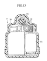
axis adjusting apparatus 5 is provided with acase 50, amotor 51 and aspeed reduction mechanism 52 which are received within thecase 50, and an extendable/retractable rod 53 extending/retracting via thespeed reduction mechanism 52 due to a driving operation of themotor 51 so as to tilt thereflector 4. - However, since the optical
axis adjusting apparatus 5 in the conventional head light for the automobile mentioned above is structured such that themotor 51 is received within thecase 50 in a substantially closed state, thecase 50 is filled with heat of themotor 51, so that there is a problem concerning a heat radiating performance of the motor. - The present invention has been achieved with such points in mind.
- It therefore is an object of the present invention to provide an optical axis adjusting apparatus of a head light for an automobile in which a heat radiating performance of a motor can be improved, an assembling property can be improved and a compact size can be achieved.
- In order to achieve the object mentioned above, the present invention is characterized in that a case is separable into two portions, and an opening portion to which a motor is inserted and an insertion hole to which an extendable/retractable rod is inserted so as to freely oscillate are provided in the same direction.
- As a result, in an optical axis adjusting apparatus of a head light for an automobile in accordance with the present invention, since an outer portion and an inner portion of the case are communicated with each other by the opening portion and the insertion hole provided in the case, heat of the motor within the case is discharged to an external portion via the opening portion and the insertion hole, so that a heat radiating performance of the motor can be improved. Further, since shapes of the opening portion and the insertion hole substantially coincide with outer shapes of the motor and the extendable/retractable rod, the opening portion and the insertion hole serve as a guide at a time of assembling a first case, so that an assembling property can be improved. Further, since the motor is inserted into the opening portion, whereby it is possible to reduce a width in an extending/retracting direction of the extendable/retractable rod at a degree corresponding to a size between an outer surface of the case and the motor in comparison with the structure in which the motor is received within the case in a substantially sealed state, it is possible to achieve a compact size.
-
- Fig. 1 is a vertical sectional view showing a first embodiment of an optical axis adjusting apparatus in a head light for an automobile in accordance with the present invention in a state of being mounted to a lamp housing;
- Fig. 2 is a vertical sectional view of the other case;
- Fig. 3 is a vertical sectional view of a state in which a motor, a speed reduction mechanism and an extendable/retractable rod are assembled in the other case;
- Fig. 4 is a vertical sectional view of a state that a first case is assembled in the other case in which the motor, the speed reduction mechanism and the extendable/retractable rod are assembled;
- Fig. 5 is a schematic view as seen along an arrow V in Fig. 3;
- Fig. 6 is a schematic view as seen along an arrow VI in Fig. 4;
- Fig. 7 is a schematic view as seen along an arrow VII in Fig. 4;
- Fig. 8 is a vertical sectional view showing a second embodiment of an optical axis adjusting apparatus in a head light for an automobile in accordance with the present invention and showing the first case which is integrally formed with a lamp housing;
- Fig. 9 is a vertical sectional view of the other case;
- Fig. 10 is a vertical sectional view of a state in which a motor, a speed reduction mechanism and an extendable/retractable rod are assembled in the other case;
- Fig. 11 is a vertical sectional view of a state that the first case is assembled in the other case in which the motor, the speed reduction mechanism and the extendable/retractable rod are assembled;
- Fig. 12 is a partly vertical sectional view showing an optical axis adjusting apparatus in a head light for an automobile in accordance with the conventional art;
- Fig. 13 is a sectional view taken along a line XIII-XIII in Fig. 12; and
- Fig. 14 is a sectional view taken along a line XIV-XIV in Fig. 12.
-
- A description will be given of two embodiments of an optical axis adjusting apparatus in a head light for an automobile in accordance with the present invention with reference to Figs. 1 to 11.
- Figs. 1 to 7 show a first embodiment of the optical axis adjusting apparatus in the head light for the automobile in accordance with the present invention. In the drawings, the same reference numerals denote the same elements as those in Figs. 12 to 14.
- In the drawings,
reference numeral 6 denotes an optical axis adjusting apparatus in accordance with the present invention. The opticalaxis adjusting apparatus 6 is constituted by twoseparable cases motor 62, aspeed reduction mechanism 63 and an extendable/retractable rod 64. - A
first case 60 of two separable cases is, for example, made of resin as shown in Figs. 1, 4 and 6, and is formed in a shape in which a front portion is closed and a rear portion is opened. Themotor 62 is provided with arectangular opening portion 600 to which themotor 62 is inserted and which substantially coincides with an outer shape of themotor 62, and acircular insertion hole 601 to which the extendable/retractable rod 64 is inserted so as to freely oscillate and which substantially coincides with an outer shape of the extendable/retractable rod 64. Theseopening portion 600 and theinsertion hole 601 are provided in the same direction, that is, in an extending/retracting direction of the extendable/retractable rod 64. In this case, two recessportions 602 for preventing the extendable/retractable rod 64 from rotating are provided in theinsertion hole 601. Further, two circular throughholes 603 are respectively provided in thisfirst case 60. Further, aholder portion 604 for holding thespeed reduction mechanism 63 is integrally protruded rearward in thisfirst case 60. - The
other case 61 among the two separable cases is, for example, made of resin as shown in Figs. 1 to 5 and 7, and is formed in a shape in which a front portion is opened and a rear portion is closed. A motor holder portion for holding themotor 62 and speed reductionmechanism holder portions speed reduction mechanism 63 are respectively protruded forward in theother case 61 in an integral manner. The speed reduction mechanism holder portion is constituted by a first speed reductionmechanism holder portion 611 having a large diameter and formed in a cylindrical shape, and a second speed reductionmechanism holder portion 611 having a small diameter and formed in a cylindrical shape. Further, aconnector portion 613 is integrally protruded rearward in theother case 61. Threeterminals 614 are provided in thisconnector portion 613 in accordance with an insert molding. Further, two circular throughholes 615 are respectively provided in theother case 61 in correspondence to thethrough hole 603 in thefirst case 60. - An
electric circuit board 620 is mounted to themotor 62 and is electrically connected thereto. Theelectric circuit board 620 is constituted by a printed circuit board (PCB) or the like on which a control circuit and the like are printed and wired. Aposition sensor 621 such as a potentiometer or the like is mounted on theelectric circuit board 620. A rotation of themotor 62 is detected by theposition sensor 621, and the rotation of themotor 62 is controlled by the control circuit. - The
speed reduction mechanism 63 is, as shown in Figs. 1 and 3 to 5, constituted by aworm 630 fixed to a rotary shaft of themotor 62, aworm wheel 631 engaged with theworm 630, anidle gear 632 integrally formed with theworm wheel 631, and anoutput gear 633 engaged with theidle gear 632. A femalefeeding screw portion 634 is provided in a center of theoutput gear 633. Further,circular recess portions output gear 633 and theidle gear 632. - The extendable/
retractable rod 64 is, as shown in Figs. 1 and 3 to 5, constituted by aspherical portion 640 disposed at one end portion, a malefeeding screw portion 641 at another end portion, and twoconvex portions 642 for preventing another end portion from rotating. The malefeeding screw portion 641 is screwed into the femalefeeding screw portion 634 of theoutput gear 633. - Next, a description will be given of a process of assembling the optical
axis adjusting apparatus 6 in accordance with the present invention structured in the manner mentioned above. - At first, the
electric circuit board 620, themotor 62, thespeed reduction mechanism 63 and the extendable/retractable rod 64 are assembled in theother case 61 shown in Fig. 2 (refer to Fig. 3). That is, theelectric circuit board 620 is fixed to theother case 61. Themotor 62 is held by themotor holder portion 610. The cylindrical first speed reductionmechanism holder portion 611 and second speedreduction mechanism holder 612 are set to thecircular recess portions output gear 633 and theidle gear 632, whereby theoutput gear 633 and theidle gear 632 are rotatably held in the first speed reductionmechanism holder portion 611 and the second speedreduction mechanism holder 612. - Then, the
first case 60 is assembled in theother case 61 in which theelectric circuit board 620, themotor 62, thespeed reduction mechanism 63 and the extendable/retractable rod 64 are assembled (refer to Fig. 4). That is, themotor 62 is inserted into theopening portion 600, the extendable/retractable rod 64 is inserted to theinsertion hole 601 so as to freely oscillate, the rotation preventingconvex portion 642 is fitted to the rotation preventingrecess portion 602 so as to freely oscillate, and theoutput gear 633 is rotatably held by theholder portion 604 together with the first speed reductionmechanism holder portion 611. In the manner mentioned above, the opticalaxis adjusting apparatus 6 in accordance with the present invention can be assembled. - Then, the optical
axis adjusting apparatus 6 in accordance with the present invention is mounted to thelamp housing 1, and thespherical portion 640 of the extendable/retractable rod 64 is fitted to a spherical recess portion (not shown) of the reflector 4 (refer to Fig. 1). That is, the opticalaxis adjusting apparatus 6 in accordance with the present invention is arranged inside thelamp chamber 3, theconnector portion 613 is inserted to awindow portion 10 provided in thelamp housing 1, an O-ring 11 is interposed between thelamp housing 1 and thecase 61, a screw (not shown) is inserted into the circular throughholes axis adjusting apparatus 6 is mounted to thelamp housing 1 by means of the screw. As a result, the opticalaxis adjusting apparatus 6 in accordance with the present invention is arranged between thelamp housing 1 and thereflector 4. - Since the optical
axis adjusting apparatus 6 in accordance with the present invention in this embodiment is structured in a manner mentioned below, a heat radiating performance of themotor 62 can be improved, an assembling property can be improved and a compact size can be achieved. - That is, since the optical
axis adjusting apparatus 6 in accordance with the present invention in this embodiment is structured such that an outer portion and an inner portion of thecases opening portion 600 and theinsertion hole 601 which are provided in thefirst case 60, heat of themotor 62 within thecases opening portion 600 and theinsertion hole 601, so that a heat radiating performance of themotor 62 can be improved. - Further, since the optical
axis adjusting apparatus 6 in accordance with the present invention in this embodiment is structured such that the shapes of theopening portion 600 and theinsertion hole 601 substantially coincide with the outer shapes of themotor 62 and the extendable/retractable rod 64, theopening portion 600 and theinsertion hole 601 serve as a guide at a time of assembling thefirst case 60 in theother case 61 in which theelectric circuit board 620, themotor 62, thespeed reduction mechanism 63 and the extendable/retractable rod 64 are assembled, so that an assembling property can be improved. - Further, since the optical
axis adjusting apparatus 6 in accordance with the present invention in this embodiment is, as shown in Fig. 1, structured such that themotor 62 is inserted to theopening portion 600, whereby it is possible to reduce a width in an extending/retracting direction of the extendable/retractable rod 64 at a degree of a size W between the outer surface of thecase 50 and themotor 62 in comparison with the structure in which themotor 62 is received within the case 50 (shown by a double-dotted chain line in Fig. 1) in a substantially sealed state, so that a compact size can be achieved. - In particular, since the optical
axis adjusting apparatus 6 in this embodiment is structured such that the case is constituted by two separable cases, and theother case 62 within which theelectric circuit board 620, themotor 62, thespeed reduction mechanism 63 and the extendable/retractable rod 64 are assembled is assembled in thefirst case 60, an assembling property can be further improved. - Figs. 8 to 11 show a second embodiment of an optical axis adjusting apparatus in a head lamp for an automobile in accordance with the present invention. In the drawings, the same reference numerals as those of Figs. 1 to 7 and Figs. 12 to 14 denote the same elements.
- An optical axis adjusting apparatus 6' in accordance with the present invention in this embodiment is, as shown in Figs. 8 to 11, such that the first case 60' is constituted by a part of the
housing 1. That is, arecess portion 12 for the case is provided in a part of thelamp housing 1, and theopening portion 600, theinsertion hole 601, the rotation preventingrecess portion 602 and theholder portion 604 are provided in therecess portion 12. - On the contrary, as shown in Figs. 9 to 11, a
seal recess portion 616 is provided in an opening end portion of theother case 61. The optical axis adjusting apparatus 6' is constructed by assembling theother case 61 in the first case 60' integrally formed with thelamp housing 1 with interposing an O-ring 617. - The structure in accordance with the second embodiment can achieve the same operations and effects as those of the first embodiment mentioned above.
- In particular, since the second embodiment is structured such that the first case 60' is constituted by a part of the
lamp housing 1, the number of parts can be reduced. - Further, in the second embodiment, since the
other case 61 protrudes outside thelamp housing 1 and the first case 60' protrudes inside thelamp housing 1, a protruding size to the inside from thelamp housing 1 is reduced in comparison with the structure in which a whole of the optical axis adjusting apparatus is arranged inside thelamp housing 1. As a result, it is possible to reduce a depth of the head light for the automobile. - In this case, in the second embodiment, the first case 60' is integrally formed with the
lamp housing 1, however, in accordance with the present invention, theother case 60 may be integrally formed with thelamp housing 1 in a reverse manner. - Further, in the first and second embodiments mentioned above, the structure is made such that the
motor 62, thespeed reduction mechanism 63 and the extendable/retractable rod 64 are assembled within theother case 61 and thereafter theother case 61 is assembled in thefirst case 60 or 60', however, in accordance with the present invention, the structure may be made such that themotor 62, thespeed reduction mechanism 63 and the extendable/retractable rod 64 are assembled within thefirst case 60 or 60' and thereafter thefirst case 60 or 60' is assembled in theother case 61. - As mentioned above, in the optical axis adjusting apparatus in the head light for the automobile in accordance with the present invention, since the outer portion and the inner portion of the case are communicated with each other by the opening portion and the insertion hole provided in the case, the heat of the motor within the case is discharged to the external portion via the opening portion and the insertion hole, so that a heat radiating performance of the motor can be improved. Further, since the shapes of the opening portion and the insertion hole substantially coincide with the outer shapes of the motor and the extendable/retractable rod, the opening portion and the insertion hole serve as the guide at a time of assembling the first case, so that an assembling property can be improved. Further, since the motor is inserted into the opening portion, whereby it is possible to reduce the width in the extending/retracting direction of the extendable/retractable rod at a degree corresponding to the size between the outer surface of the case and the motor in comparison with the structure in which the motor is received within the case in a substantially sealed state, it is possible to achieve a compact size.
- The entire contents of Japanese Patent Application P2000-30255 (filed on February 2, 2000) are incorporated herein by reference.
- Although the invention has been described above by reference to certain embodiments of the invention, the invention is not limited to the embodiments described above. Modifications and variations of the embodiments described above will occur to those skilled in the art, in light of the above teachings. The scope of the invention is defined with reference to the following claims.
Claims (4)
- In a head light for an automobile, where:characterized in that an opening portion to which said motor is inserted and an insertion hole to which said extendable/retractable rod is inserted so as to freely oscillate are provided in one case of said two separable cases in the same direction.a lamp chamber is defined by a lamp housing and a lens; anda light source bulb is arranged and a reflector for reflecting a light beam output from said light source bulb to said lens side is arrangedso as to freely tilt within said lamp chamber, an optical axis adjusting apparatus is arranged between said lamp housing and said reflector wherein said reflector is tilted in accordance with an operation of said optical axis adjusting apparatus, so that an optical axis is adjusted,said optical axis adjusting apparatus in a head light for an automobile is characterized in that:said optical axis adjusting apparatus in a head light for an automobile comprises two separable cases, a motor and a speed reduction mechanism which are received within said cases, and an extendable/retractable rod extending/retracting via said speed reduction mechanism by driving said motor so as to tilt said reflector; and
- An optical axis adjusting apparatus in a head light for an automobile according to claim 1, characterized in that said one case or said other case is constituted by said lamp housing.
- An optical axis adjusting apparatus in a head light for an automobile according to claim 1 or 2, characterized in that said optical axis adjusting apparatus is assembled in said one case after assembling said motor, said speed reduction mechanism and said extendable/retractable rod within said other case of said two separable cases.
- An optical axis adjusting apparatus in a head light for an automobile according to claim 1 or 2, characterized in that said optical axis adjusting apparatus is assembled in said other case after assembling said motor, said speed reduction mechanism and said extendable/retractable rod within said one case of said two separable cases.
Applications Claiming Priority (2)
| Application Number | Priority Date | Filing Date | Title |
|---|---|---|---|
| JP2000030255 | 2000-02-02 | ||
| JP2000030255A JP2001216818A (en) | 2000-02-02 | 2000-02-02 | Optical axis adjuster of headlamp for motorcar |
Publications (3)
| Publication Number | Publication Date |
|---|---|
| EP1122127A2 true EP1122127A2 (en) | 2001-08-08 |
| EP1122127A3 EP1122127A3 (en) | 2001-09-12 |
| EP1122127B1 EP1122127B1 (en) | 2007-05-02 |
Family
ID=18555294
Family Applications (1)
| Application Number | Title | Priority Date | Filing Date |
|---|---|---|---|
| EP01102266A Expired - Lifetime EP1122127B1 (en) | 2000-02-02 | 2001-01-31 | Optical axis adjusting apparatus in head light for automobile |
Country Status (4)
| Country | Link |
|---|---|
| EP (1) | EP1122127B1 (en) |
| JP (1) | JP2001216818A (en) |
| KR (1) | KR100486341B1 (en) |
| DE (1) | DE60128166T2 (en) |
Cited By (6)
| Publication number | Priority date | Publication date | Assignee | Title |
|---|---|---|---|---|
| FR2842479A1 (en) * | 2002-07-19 | 2004-01-23 | Valeo Vision | Headlamp with electronic control card for motor vehicle, uses separate housing for correction motor and electronic card providing control functions for the headlamp unit |
| EP1925497A3 (en) * | 2006-11-24 | 2009-04-01 | Ichikoh Industries, Ltd. | Vehicle headlight leveling device and vehicle headlight equipped with leveling device |
| CN101469839B (en) * | 2007-12-24 | 2012-09-05 | 上海小糸车灯有限公司 | Light modulation executor for automobile headlamp |
| CN106764945A (en) * | 2016-11-24 | 2017-05-31 | 武汉通畅汽车电子照明有限公司 | The mounting structure of car light light-modulating motor support, vehicle lamp assembly and automobile |
| CN109253428A (en) * | 2013-08-23 | 2019-01-22 | 株式会社小糸制作所 | Lighting device |
| WO2022128350A1 (en) * | 2020-12-16 | 2022-06-23 | HELLA GmbH & Co. KGaA | Illumination device and mounting method |
Families Citing this family (4)
| Publication number | Priority date | Publication date | Assignee | Title |
|---|---|---|---|---|
| JP4428632B2 (en) * | 2004-03-10 | 2010-03-10 | 株式会社小糸製作所 | Actuator |
| JP2008273232A (en) * | 2007-04-25 | 2008-11-13 | Ichikoh Ind Ltd | Leveling device of vehicular headlight |
| JP5221210B2 (en) * | 2008-05-30 | 2013-06-26 | アスモ株式会社 | Lamp device and vehicle lamp device |
| CN107310462A (en) * | 2016-04-26 | 2017-11-03 | 上汽通用汽车有限公司 | It is a kind of to be used to adjust the adjustment structure that matching degree is installed between vehicle lamp assembly |
Citations (2)
| Publication number | Priority date | Publication date | Assignee | Title |
|---|---|---|---|---|
| JPH08164789A (en) | 1994-12-14 | 1996-06-25 | Ichikoh Ind Ltd | Optical axis adjusting device of headlight |
| JP2000030255A (en) | 1998-07-14 | 2000-01-28 | Yamaha Corp | Recording method of optical disk and recorder thereof |
Family Cites Families (3)
| Publication number | Priority date | Publication date | Assignee | Title |
|---|---|---|---|---|
| US3953726A (en) * | 1974-12-06 | 1976-04-27 | Scarritt Sr Frank M | Infinitely adjustable level light |
| ES244984Y (en) * | 1978-08-03 | 1980-12-01 | DEVICE TO VARY THE POSITION OF THE HEADLIGHTS OF A VEHICLE IN FUNCTION TO THE CARGO CARRIED | |
| FR2779804B1 (en) * | 1998-06-11 | 2000-09-29 | Valeo Vision | MOTOR VEHICLE PROJECTOR PROVIDED WITH IMPROVED COOLING MEANS, AND ASSOCIATED PLATE CORRECTOR |
-
2000
- 2000-02-02 JP JP2000030255A patent/JP2001216818A/en active Pending
- 2000-12-20 KR KR10-2000-0078941A patent/KR100486341B1/en not_active IP Right Cessation
-
2001
- 2001-01-31 DE DE60128166T patent/DE60128166T2/en not_active Expired - Fee Related
- 2001-01-31 EP EP01102266A patent/EP1122127B1/en not_active Expired - Lifetime
Patent Citations (2)
| Publication number | Priority date | Publication date | Assignee | Title |
|---|---|---|---|---|
| JPH08164789A (en) | 1994-12-14 | 1996-06-25 | Ichikoh Ind Ltd | Optical axis adjusting device of headlight |
| JP2000030255A (en) | 1998-07-14 | 2000-01-28 | Yamaha Corp | Recording method of optical disk and recorder thereof |
Cited By (7)
| Publication number | Priority date | Publication date | Assignee | Title |
|---|---|---|---|---|
| FR2842479A1 (en) * | 2002-07-19 | 2004-01-23 | Valeo Vision | Headlamp with electronic control card for motor vehicle, uses separate housing for correction motor and electronic card providing control functions for the headlamp unit |
| EP1925497A3 (en) * | 2006-11-24 | 2009-04-01 | Ichikoh Industries, Ltd. | Vehicle headlight leveling device and vehicle headlight equipped with leveling device |
| US7658523B2 (en) | 2006-11-24 | 2010-02-09 | Ichikoh Industries, Ltd. | Vehicle headlight leveling device and vehicle headlight equipped with leveling device |
| CN101469839B (en) * | 2007-12-24 | 2012-09-05 | 上海小糸车灯有限公司 | Light modulation executor for automobile headlamp |
| CN109253428A (en) * | 2013-08-23 | 2019-01-22 | 株式会社小糸制作所 | Lighting device |
| CN106764945A (en) * | 2016-11-24 | 2017-05-31 | 武汉通畅汽车电子照明有限公司 | The mounting structure of car light light-modulating motor support, vehicle lamp assembly and automobile |
| WO2022128350A1 (en) * | 2020-12-16 | 2022-06-23 | HELLA GmbH & Co. KGaA | Illumination device and mounting method |
Also Published As
| Publication number | Publication date |
|---|---|
| KR100486341B1 (en) | 2005-04-29 |
| KR20010077946A (en) | 2001-08-20 |
| EP1122127A3 (en) | 2001-09-12 |
| JP2001216818A (en) | 2001-08-10 |
| DE60128166T2 (en) | 2007-08-30 |
| DE60128166D1 (en) | 2007-06-14 |
| EP1122127B1 (en) | 2007-05-02 |
Similar Documents
| Publication | Publication Date | Title |
|---|---|---|
| EP1122127B1 (en) | Optical axis adjusting apparatus in head light for automobile | |
| EP1925497B1 (en) | Vehicle headlight leveling device and vehicle headlight equipped with leveling device | |
| KR100434938B1 (en) | Vehicle lamp | |
| JP4671852B2 (en) | Vehicle lighting | |
| US20050213339A1 (en) | Actuator | |
| EP1612472B1 (en) | Vehicle lighting apparatus | |
| KR20060128661A (en) | Vehicular lamp | |
| CN108368923B (en) | Fixing part, self-aligning bearing mechanism, actuator and lamp | |
| JP2005222859A (en) | Vehicle lighting fixture | |
| US6672747B2 (en) | Vehicle headlamp having removable lighting control unit | |
| US7572042B2 (en) | Leveling device for vehicular headlamp | |
| CN107883338B (en) | Vehicle headlamp | |
| JP3424508B2 (en) | Optical axis adjustment drive unit of headlight optical axis adjustment device | |
| EP1188984B1 (en) | Light source bulb of lighting device for vehicle | |
| JP2971708B2 (en) | High mount stop lamp | |
| CN217294379U (en) | Automobile headlight mask opening and closing driving device | |
| JP4623049B2 (en) | Leveling device for vehicle headlamps | |
| US6513956B1 (en) | Lamp housing assembly | |
| JP3274753B2 (en) | Headlights for vehicles | |
| JP4010100B2 (en) | Light source bulb for vehicle lamp | |
| US6697572B2 (en) | Camera | |
| JP2003043557A (en) | Stroboscope device | |
| JPH0657515B2 (en) | Lighting angle adjustment device for automobile headlights | |
| JP2002093220A (en) | Light source bulb of automobile light | |
| CN117869822A (en) | Head lamp module, car lamp and vehicle |
Legal Events
| Date | Code | Title | Description |
|---|---|---|---|
| PUAI | Public reference made under article 153(3) epc to a published international application that has entered the european phase |
Free format text: ORIGINAL CODE: 0009012 |
|
| PUAL | Search report despatched |
Free format text: ORIGINAL CODE: 0009013 |
|
| 17P | Request for examination filed |
Effective date: 20010131 |
|
| AK | Designated contracting states |
Kind code of ref document: A2 Designated state(s): DE FR GB Kind code of ref document: A2 Designated state(s): AT BE CH CY DE DK ES FI FR GB GR IE IT LI LU MC NL PT SE TR |
|
| AX | Request for extension of the european patent |
Free format text: AL;LT;LV;MK;RO;SI |
|
| AK | Designated contracting states |
Kind code of ref document: A3 Designated state(s): AT BE CH CY DE DK ES FI FR GB GR IE IT LI LU MC NL PT SE TR |
|
| AX | Request for extension of the european patent |
Free format text: AL;LT;LV;MK;RO;SI |
|
| AKX | Designation fees paid |
Free format text: DE FR GB |
|
| GRAP | Despatch of communication of intention to grant a patent |
Free format text: ORIGINAL CODE: EPIDOSNIGR1 |
|
| GRAS | Grant fee paid |
Free format text: ORIGINAL CODE: EPIDOSNIGR3 |
|
| GRAA | (expected) grant |
Free format text: ORIGINAL CODE: 0009210 |
|
| AK | Designated contracting states |
Kind code of ref document: B1 Designated state(s): DE FR GB |
|
| REG | Reference to a national code |
Ref country code: GB Ref legal event code: FG4D |
|
| RIN1 | Information on inventor provided before grant (corrected) |
Inventor name: YONEYAMA, HIROKAZUC/O ICHIKOH INDUSTRIES, LTD., Inventor name: FUKUSHIMA, SHOUICHIC/O ICHIKOH INDUSTRIES, LTD., |
|
| REF | Corresponds to: |
Ref document number: 60128166 Country of ref document: DE Date of ref document: 20070614 Kind code of ref document: P |
|
| ET | Fr: translation filed | ||
| PLBE | No opposition filed within time limit |
Free format text: ORIGINAL CODE: 0009261 |
|
| STAA | Information on the status of an ep patent application or granted ep patent |
Free format text: STATUS: NO OPPOSITION FILED WITHIN TIME LIMIT |
|
| 26N | No opposition filed |
Effective date: 20080205 |
|
| PGFP | Annual fee paid to national office [announced via postgrant information from national office to epo] |
Ref country code: DE Payment date: 20090129 Year of fee payment: 9 |
|
| PGFP | Annual fee paid to national office [announced via postgrant information from national office to epo] |
Ref country code: GB Payment date: 20090128 Year of fee payment: 9 |
|
| PGFP | Annual fee paid to national office [announced via postgrant information from national office to epo] |
Ref country code: FR Payment date: 20090113 Year of fee payment: 9 |
|
| GBPC | Gb: european patent ceased through non-payment of renewal fee |
Effective date: 20100131 |
|
| REG | Reference to a national code |
Ref country code: FR Ref legal event code: ST Effective date: 20100930 |
|
| PG25 | Lapsed in a contracting state [announced via postgrant information from national office to epo] |
Ref country code: FR Free format text: LAPSE BECAUSE OF NON-PAYMENT OF DUE FEES Effective date: 20100201 |
|
| PG25 | Lapsed in a contracting state [announced via postgrant information from national office to epo] |
Ref country code: DE Free format text: LAPSE BECAUSE OF NON-PAYMENT OF DUE FEES Effective date: 20100803 |
|
| PG25 | Lapsed in a contracting state [announced via postgrant information from national office to epo] |
Ref country code: GB Free format text: LAPSE BECAUSE OF NON-PAYMENT OF DUE FEES Effective date: 20100131 |