EP1122010B1 - Cutting tool of polycrystalline hard sintered material - Google Patents
Cutting tool of polycrystalline hard sintered material Download PDFInfo
- Publication number
- EP1122010B1 EP1122010B1 EP00125694A EP00125694A EP1122010B1 EP 1122010 B1 EP1122010 B1 EP 1122010B1 EP 00125694 A EP00125694 A EP 00125694A EP 00125694 A EP00125694 A EP 00125694A EP 1122010 B1 EP1122010 B1 EP 1122010B1
- Authority
- EP
- European Patent Office
- Prior art keywords
- cutting
- tool
- hard sintered
- sintered material
- polycrystalline hard
- Prior art date
- Legal status (The legal status is an assumption and is not a legal conclusion. Google has not performed a legal analysis and makes no representation as to the accuracy of the status listed.)
- Expired - Lifetime
Links
Images

Classifications
-
- B—PERFORMING OPERATIONS; TRANSPORTING
- B23—MACHINE TOOLS; METAL-WORKING NOT OTHERWISE PROVIDED FOR
- B23B—TURNING; BORING
- B23B27/00—Tools for turning or boring machines; Tools of a similar kind in general; Accessories therefor
- B23B27/14—Cutting tools of which the bits or tips or cutting inserts are of special material
- B23B27/141—Specially shaped plate-like cutting inserts, i.e. length greater or equal to width, width greater than or equal to thickness
- B23B27/145—Specially shaped plate-like cutting inserts, i.e. length greater or equal to width, width greater than or equal to thickness characterised by having a special shape
-
- B—PERFORMING OPERATIONS; TRANSPORTING
- B23—MACHINE TOOLS; METAL-WORKING NOT OTHERWISE PROVIDED FOR
- B23B—TURNING; BORING
- B23B2200/00—Details of cutting inserts
- B23B2200/20—Top or side views of the cutting edge
- B23B2200/201—Details of the nose radius and immediately surrounding area
-
- B—PERFORMING OPERATIONS; TRANSPORTING
- B23—MACHINE TOOLS; METAL-WORKING NOT OTHERWISE PROVIDED FOR
- B23B—TURNING; BORING
- B23B2200/00—Details of cutting inserts
- B23B2200/24—Cross section of the cutting edge
- B23B2200/245—Cross section of the cutting edge rounded
-
- B—PERFORMING OPERATIONS; TRANSPORTING
- B23—MACHINE TOOLS; METAL-WORKING NOT OTHERWISE PROVIDED FOR
- B23B—TURNING; BORING
- B23B2200/00—Details of cutting inserts
- B23B2200/28—Angles
- B23B2200/283—Negative cutting angles
-
- B—PERFORMING OPERATIONS; TRANSPORTING
- B23—MACHINE TOOLS; METAL-WORKING NOT OTHERWISE PROVIDED FOR
- B23B—TURNING; BORING
- B23B2226/00—Materials of tools or workpieces not comprising a metal
- B23B2226/12—Boron nitride
- B23B2226/125—Boron nitride cubic [CBN]
-
- Y—GENERAL TAGGING OF NEW TECHNOLOGICAL DEVELOPMENTS; GENERAL TAGGING OF CROSS-SECTIONAL TECHNOLOGIES SPANNING OVER SEVERAL SECTIONS OF THE IPC; TECHNICAL SUBJECTS COVERED BY FORMER USPC CROSS-REFERENCE ART COLLECTIONS [XRACs] AND DIGESTS
- Y10—TECHNICAL SUBJECTS COVERED BY FORMER USPC
- Y10T—TECHNICAL SUBJECTS COVERED BY FORMER US CLASSIFICATION
- Y10T407/00—Cutters, for shaping
- Y10T407/26—Cutters, for shaping comprising cutting edge bonded to tool shank
-
- Y—GENERAL TAGGING OF NEW TECHNOLOGICAL DEVELOPMENTS; GENERAL TAGGING OF CROSS-SECTIONAL TECHNOLOGIES SPANNING OVER SEVERAL SECTIONS OF THE IPC; TECHNICAL SUBJECTS COVERED BY FORMER USPC CROSS-REFERENCE ART COLLECTIONS [XRACs] AND DIGESTS
- Y10—TECHNICAL SUBJECTS COVERED BY FORMER USPC
- Y10T—TECHNICAL SUBJECTS COVERED BY FORMER US CLASSIFICATION
- Y10T407/00—Cutters, for shaping
- Y10T407/27—Cutters, for shaping comprising tool of specific chemical composition
Definitions
- the cutting tool of the polycrystalline hard sintered body containing CBN was edged by using a diamond grinder of grain size of contained diamond being around #600 and by grinding the rake face and the flank. It was found that the ridge of the cutting edge of the thus made cutting tool of sintered body had remarkable unevenness as partially and largely broken at the ridge of the cutting edge.
- the cutting tool of the polycrystalline hard sintered body of the invention is edged by grinding the flank and the rake face of the tool by means of the diamond grinder of grain diameter being around #600 to #3000, and subsequently, a coated rotary brush with diamond free abrasive grain of around #1500 to #3000 is applied so as to polish an edged vicinity.
- a coated rotary brush with diamond free abrasive grain of around #1500 to #3000 is applied so as to polish an edged vicinity. Namely, such a cutting tool can be obtained in which the surface roughness of the cutting tool is small and smooth and the ridge of the cutting edge is smoothly continued to the rake face and the flank of the tool. By smoothly continuing, cut chips can be rapidly removed.
- the angle made between a straight line bisecting the nose r and the straight cutting edges L and L' is less than 42°, the effect of dragging a face of the work is small.
- the angle in turn exceeds 45° the contacting part with the work increases, so that the cutting resistance is large, and it is difficult to secure the machining precision.
- the angle made between a straight line bisecting the nose r and the straight cutting edges L and L' is between 42° and 45°. Further, considering the balance between the machining precision and the finished surface roughness, the angle is more preferably between 43.5° and 45°.
- Table 2 shows the surface roughness and the roundness of the work after the cutting tests.
- the sample 1A where the radius of curvature in cross section of the ridge of the cutting edge was small, although the cutting resistance was small and the roundness was excellent, since the roughness of the ridge of the cutting edge was large, the roughness on the finished surface to be transferred was large, and a desired finished roughness could not be provided.
Landscapes
- Engineering & Computer Science (AREA)
- Mechanical Engineering (AREA)
- Cutting Tools, Boring Holders, And Turrets (AREA)
Description
- The present invention relates to a cutting tool of a polycrystalline hard sintered material comprising a cutting edge and as know for example from
JP- A- 6-1100302 - A material where powder of CBN is sintered with various kinds of bonding agents exhibits an excellent performance for cutting iron family metals or cast iron having high hardness. Particularly, in a machining of hardened steel having high hardness, when the machining is carried out with a tool of CBN, a roughness on a finished surface and a precision in machined size are equivalent to those of a grinding. Accordingly, the grinding using a conventional grinder is changed to a cutting using the tool of CSN in a part of the cutting of hardened steels.
- This inclination has more developed, and such a demand has recently been raised that the cutting is substituted for a machining field requiring the high precision only possible conventionally with the grinding. Objects to be cut by a tool containing CBN are materials of hard quality such as hardened steel or cast iron. It has been hardly conceived to obtain a finish surface near to a mirror surface by the cutting. A precision machining referred to herein is meant by a dimensional precision such as the surface roughness and the roundness on the cut surface.
- On the other hand, the most advanced precision cutting is a cutting of non-ferrous metal using single crystal diamond. A main application field is in a machining of aluminum based alloys such as a base board of memory disk or polygon mirror. There is nowadays a tendency to replace a single crystal with polycrystal diamond easier to machine at lower cost. In the polycrystal diamond tool, if a large unevenness is formed on a ridge of the cutting edge due to difference in steps at crystal interface, it cannot be removed even by grinding the flank or the rake face of the tool. There occur problems that this unevenness remains in the ground surface, and is transferred to a work piece to hinder the machining at high precision. A case of polycrystal diamond cutting tool described in Japanese Patent Unexamined Publication No.
Hei.6-190610 JP-A-6-190610 -
EP 0413227 A2 describes a tool with a wear protection layer. A tool having at least one cutting edge is provided with a wear protection layer provided at least in the vicinity of the cutting edge. After the cutting edge has been provided with the wear protection layer, the cutting edge is given a rounded form whereby the wear protection layer may be removed partly or completely from the cutting edge. The radius of curvature of the cutting edge is 0.03 to 0.12 mm and has a maximum roughness depth of 0.5 to 0.7 µm. The protection layer may be of titan nitride or titan carbide. - It is the object of the present invention to improve a cutting tool of a polycrystalline hard sintered body containing a cubic crystal boron nitride. This object is achieved by providing a cutting tool of a polycrystalline sintered material according to
claim 1. - In view of the problems involved with the conventional technique, when a hardened steel is subjected to the cutting, the invention is to make the surface roughness on the cut face 1.6 µm or less at Rz and to improve the dimensional precision of the roundness to be 3 µm or less. As a field of uses, many cases are of materials to be cut of diameter being around 30 mm or smaller. Namely, the superior roughness of a finished surface and the high precision in machined size are realized by improving a shape of the cutting edge and the surface roughness of the cutting tool of a polycrystalline hard sintered body containing CBN. "Rz" is meant by the average roughness of the ten point system specified by B0601 "Surface roughness - Definition and Designation" of JIS.
-
-
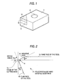
Fig. 1 is a perspective view of the cutting tool concerned with the invention; -
Fig. 2 an enlarged cross sectional view of the cutting tool concerned with the invention; -
Fig. 3 is an enlarged sectional view of the cutting tool concerned with the invention; -
Fig. 4 is a view showing the method of measuring the roughness of the ridge of the cutting edge concerned with the invention; and -
Fig. 5 is an enlarged front view showing the cutting tool concerned with the invention. - An example of the cutting tool of the polycrystalline hard sintered body to be used in the invention is shown in
Fig. 1 . A polycrystalline hard sinteredbody 11 has a double layered structure integrally united with a cementedcarbide base 3, a tool base material is formed such a manner that this double layered structure is brazed at an corner of atool base material 1 of made of the cemented carbide. Of course, the invention can be applied to a cutting tool not using the cementedcarbide base 1. The cutting tool is attached to, e.g., a holder (not shown) through an attachinghole 2. The cutting tool is, according to embodiments, enumerated as an indexable insert shown inFig. 1 or a bite directly brazed to the holder as later mentioned in an Example 3. The invention is concerned with a structure of the ridge of the cutting edge which is a most important part participated in the cutting performance of the cutting tool. - An inventor has made studies on cutting tools of the polycrystalline hard sintered body containing CBN for enabling a cutting at high precision. Studied results will be explained referring to
Figs. 2 and3 of the attached drawings.Figs. 2 and3 are enlarged views of a cross section perpendicularly to aline 16 composing a cutting edge ofFig. 1. Fig. 2 is an enlarged cross sectional view of the cutting tool having anegative land 14.Reference numeral 11 shows a polycrystalline hard sintered body, 12 is a flank of the tool, 13 is a rake face of the same, and 15 is a ridge of the cutting edge. The ridge of thecutting edge 15 is smoothly connected to anegative land 14 or to therake face 13 and to theflank 12 of the tool at radius R of curvature in cross section. A phrase of "smoothly connected" referred to herein is meant by continuously connected", in other words, "without an angular" or "no angular". Anangle θ 1 made between a horizontal line to be a reference when cutting and the negative land or the rake face of the tool is a rake angle, and anangle θ 2 between a vertical line and a flank face of the tool is a flank angle of the tool. In a case ofFig. 2 , therake angle θ 1 is minus, and in a case ofFig. 3 , the rake angle is in a plus direction and there is no negative land. θ3 is an angle made between the flank and the rake face of the tool, showing a wedge angle at the insert of the tool. - The ridge of the
cutting edge 15 is formed at a part crossing portion between theflank 12 and therake face 13 of the tool, or between theflank 12 and thenegative land 14 of the tool. The inventor has found that the radius R of curvature in cross section and a surface roughness of the ridge portion are important. It is important that the ridge of the cutting edge is formed with a curve having the radius R of curvature in cross section ranging from 5 to 30 µm, and the curve is continuously connected to theflank 12, therake face 13 or thenegative land 14 of the tool. It is found that if the surface roughness of the ridge of the cutting edge falls into the range from 0.1 to 1 µm at the average roughness (Rz) of the ten point system, an excellent finished surface roughness can be realized and the high precision machining can be performed. - Conventionally, the cutting tool of the polycrystalline hard sintered body containing CBN was edged by using a diamond grinder of grain size of contained diamond being around #600 and by grinding the rake face and the flank. It was found that the ridge of the cutting edge of the thus made cutting tool of sintered body had remarkable unevenness as partially and largely broken at the ridge of the cutting edge.
- When cutting a highly hard material as a hardened steel with the cutting tool of CBN, a shape of the ridge of the cutting edge is liable to transfer to a work. Therefore, when machining the highly hard material to be excellent in finished surface roughness, a cutting tool was required to have a smooth and small surface roughness, and to be less in breakage of CBN at the ridge of the cutting edge. In case a cutting resistance is high, the work piece is easily caused with a so-called chatter on the surface thereof. For solving the problems of the invention, the inventor accordingly considered it the most important that the surface roughness of the ridge of the cutting edge was made small and smooth, and secondly it an important theme to reduce the cutting resistance.
- To produce the cutting tool having the ridge of the cutting edge of the simply small surface roughness, a cutting edge could be formed taking time and labor by means of the diamond grinder having small grains of around #3000 to #14000. But it was difficult to smoothly continue the rake face and the flank of the tool to the ridge of the cutting edge.
- The cutting tool of the polycrystalline hard sintered body of the invention is edged by grinding the flank and the rake face of the tool by means of the diamond grinder of grain diameter being around #600 to #3000, and subsequently, a coated rotary brush with diamond free abrasive grain of around #1500 to #3000 is applied so as to polish an edged vicinity. Namely, such a cutting tool can be obtained in which the surface roughness of the cutting tool is small and smooth and the ridge of the cutting edge is smoothly continued to the rake face and the flank of the tool. By smoothly continuing, cut chips can be rapidly removed.
- Next, for lowering the cutting resistance, it was studied to reduce the radius R of curvature in cross section. In this course, if the radius R of curvature in cross section was too small, an aimed surface roughness could not be industrially provided, because unevenness could not be smoothened at a small radius of curvature in cross section. Then, samples of various kinds of radius of curvature in cross section were prepared and investigated by the above mentioned polishing method. As a result, if the radius R of curvature in cross section ranged from 5 to 30 µm, the cutting tool of small cutting resistance could be provided. For developing, it was assumed that the radius R of curvature in cross section had to be by far smaller than 5 µm, but unexpectedly it was found that the surface roughness was made better at 5 µm or more.
- For realizing the surface roughness of the invention by polishing to remove breakage by free abrasive grains after polishing the edged vicinity as mentioned above, the radius R of curvature in cross section of the ridge of the cutting edge is preferably 5 µm or more. If exceeding 30 µm, since the substantial rake angle of the tool becomes large in the minus direction, the cutting resistance increases and the cutting quality decreases during machining. In particular, in case machining the highly hard material at the high precision, since a thrust force is high and its fluctuation amount is large, it is difficult to get a high precision of machining size. Therefore, it is preferable that the radius R of curvature in cross section of the ridge of the cutting edge ranges from 5 to 30 µm.
- On the other hand, in the machining of the highly hard material by the conventional grinding, the finished surface roughness is around 1.6 µm or less at the average roughness (Rz) of the ten point system, and this is aimed by the invention. For accomplishing this aim, preferably the surface roughness of the ridge of the cutting edge of the cutting tool is 1.0 µm or less at the average roughness (Rz) of the ten point system. For finishing the surface roughness of the ridge of the cutting edge to be less than 0.1 µm, much labor is required and not desirable from the viewpoint of economics, and it is preferable that the surface roughness of the ridge of the cutting edge ranges from 0.1 µm or more to 1.0 µm or less.
- Since the cutting edge of the tool is worn as continuing the machining, the ridge of the cutting edge moves backward, but a new ridge of the cutting edge is to be formed from the worn flank and the rake face or the negative land of the tool. For maintaining an excellent surface roughness during continuously machining, the surface roughness of the rake face or the negative land should be small. Considering that the requisite surface roughness of the ridge of the cutting edge is below 1.0 µm and the surface roughness increase during cutting, it is preferable that the surface roughness of the rake face and the negative land of the tool ranges from 0.1 to 0.5 m at the average roughness (Rz) of the ten point system.
- On the other hand, for machining the highly hard material, a material for a tool is required to have a high hardness. Therefore, a content of CBN in the polycrystalline hard sintered body should be 20 vol% or more and 95 vol% or less. Considering the hardness, a single crystal CBN may be taken as a material for a tool in such a machining application. But, the single crystal material has a problem of easily generating breakage resulting in cleavages, and it is preferable in the machining of the highly hard material, to employ a polycrystalline CBN which is not liable to cleave.
- In case the
wedge angle θ 3 which is between the flank and the rake face of the tool or between the flank and the negative land of the tool is less than 65° , the wedge angle is small. Therefore, a breakage is easy to occur at an initial period of cutting the highly hard material. In case the above mentioned wedge angle is more than 125° , since the cutting resistance remarkably increases, a required precision machining size is not available. Also a desired finished surface roughness is provided. Thus, it is preferable that the wedge angle which is between the flank and the rake face of the tool or the flank and the negative land of the tool is 65° to 125°. - For setting the roughness of the ridge of the cutting edge within the range of 0.1 to 1.0 µm, it is preferable that average grain diameter of the contained polycrystalline CBN is below 5 µm, desirably below 1 µm. In case the average grain diameter of the contained CBN is less than 0.01 µm, the fine grains easily cohere at one portion in the sintered body, and the insert is easily broken thereby. So, preferably, the average grain diameter of the polycrystalline CBN sintered body ranges from 0.01 to 5 µm. Further, a cemented carbide or steel materials may be considered as the base material for the tool combining the hard sintered body. The base material for the tool is also required to have the high rigidity for machining the highly hard material. As the base material for the tool, therefore, the cemented carbide is most suited.
- As shown in
Fig. 5 , in addition, a pair of straight cutting edges L and L' continued from respective terminals of the nose r of the polycrystalline hard sintered body toward the side of an indexable insert have respective lengths within the range of 0.2 to 0.6 mm, and in case an angle made between a straight line bisecting the nose r and the straight cutting edges L and L' is between 42° und 45°, since the part of this straight cutting edge is finished as including a face to be machined in a cutting machining, the finished roughness is considerably improved. - In case the length of the straight cutting edge is less than 0.2 mm, an effect dragging a face of the work is small, and in case the length in turn exceeds 0.6 mm, a contacting part with the work increases, so that the cutting resistance is large, and it is difficult to secure the precision machining. Taking the above mentioned matters into consideration, it is preferable that the length of the straight cutting edge ranges from 0.2 to 0.6 (mm). Further, considering the balance between the machining precision and the finished surface roughness, a range from 0.3 to 0.5 (mm) is more preferable.
- Similarly, in case the angle made between a straight line bisecting the nose r and the straight cutting edges L and L' is less than 42°, the effect of dragging a face of the work is small. On the other hand, in case the angle in turn exceeds 45°, the contacting part with the work increases, so that the cutting resistance is large, and it is difficult to secure the machining precision. Taking the above mentioned matters into consideration, preferably, the angle made between a straight line bisecting the nose r and the straight cutting edges L and L' is between 42° and 45°. Further, considering the balance between the machining precision and the finished surface roughness, the angle is more preferably between 43.5° and 45°.
- For more improving the finished surface roughness and lengthening the tool life, if a coated layer is formed on the surface of the polycrystalline hard sintered body by a chemical or physical vapor deposition, wear of the tool decreases. Therefore, it is preferably enable to maintain the excellent finished surface roughness for long period of time.
- Explanation will be made to Examples of the cutting tool of the invention as follows.
- Investigations were made to influences given to the finished surface roughness of the work piece and the machining precision by the roughness of the ridge of the cutting edge and the radius of curvature in cross section of the ridge of the cutting edge of the tool of the polycrystalline hard sintered body containing CBN. Table 1 shows examples of the indexable inserts of the polycrystalline sintered body containing the prepared various CBN. Each wedge angle of the inserts of the tools was 83°.
- The indexable inserts in Table 1 have polycrystalline hard sintered
bodies 11 brazed at the angular of thebase material 1 as shown inFig. 1 , containing 50 vol% of average grain diameter being 0.5 to 1 µm. The polishing was carried out with #1000 diamond grinder for edging. The diamond free ground grains of diameter being 5 to 8 µm (equivalent to #2000) was coated on the surface of a rotating brush, and pressed from the rake face of the indexable insert, whereby a honing machine was performed on the ridge of the cutting edge of the tool. When the machining time was changed, and the radii of curvature in cross section of the ridge of the cutting edge were variously changed for making samples. - The radius of curvature in cross section of the ridge of the cutting edge was measured with a con-tracer. The measuring principle of the con-tracer is the same as that of the surface roughness measuring gauge. The curvature of a curve obtained by making equal a longitudinal magnification and lateral magnification for measuring. As shown in
Fig. 4 , thecutting tool 1 was inclined 45° on aV block 23, and the roughness of the ridge of the cutting edge of each sample was measured. The roughness of the ridge of thecutting edge 15 was measured under the following conditions and a terminal 22 shaped as a knife edge directs along a direction of the ridge of thecutting edge 15 of the cutting tool. - Shape of a measurer: a terminal shaped as the knife edge
- Measuring length: 1 mm
- Feeding rate of the measurer: 0.03 mm/sec
- Cut off length: 0.08 mm
- Longitudinal magnification for measuring: 20,000 times
- Lateral magnification for measuring: 100 times
- As a result, in the sample 1A where the radius of curvature in cross section of the ridge of the cutting edge was small, it was seen that chipping generated on the ridge of the cutting edge when grinding the rake face or the flank of the tool could not be removed by the honing, and surface roughness was thereby large. These five samples were subjected to the cutting test under the following conditions.
- The work piece and the cutting conditions are shown under.
- Work piece: Cylindrical carbonized and hardened steel (SCM415)
Cutting of inner diameter of the material of 10 mm inner diameter - Hardness of work piece: HRc62
- Circumferential surface velocity of work piece: 100 (m/min)
- Cut depth of the tool: 0.05 (mm)
- Feeding rate of the tool: 0.03 (mm/rev)
- Cutting time: 5 (min)
- Machining method: Inner diameter boring machine
- Requested roughness of finished surface:
- Rz = 1.6 (µm) or less
- Requested roundness: 3 µm or less
- Table 2 shows the surface roughness and the roundness of the work after the cutting tests. In the sample 1A where the radius of curvature in cross section of the ridge of the cutting edge was small, although the cutting resistance was small and the roundness was excellent, since the roughness of the ridge of the cutting edge was large, the roughness on the finished surface to be transferred was large, and a desired finished roughness could not be provided.
- On the other hand, in the sample 1E where the radius of curvature in cross section of the ridge of the cutting edge was large, although the surface roughness of the ridge of the cutting edge was small and the finished surface roughness to be transferred was excellent, since the cutting resistance was large and fluctuation thereby was large and a desired finished roughness could not be provided.
- In contrast, in the samples 1B to 1D within the claimed range of the invention, it was seen that the surface roughness of the ridge of the cutting edge was small, and the excellent finished surface roughness was thereby provided. In addition, as the radius of curvature in cross section of the ridge of the cutting edge was small, increasing of the cutting resistance was controlled, and the roundness was kept within the requested precision. The high precision machining was apparent.
[Table 2] Sample numbers Surface roughness Rz in inner diameter of work pieces Roundness Com. 1A 2.12(µm) 0.9(µm) Inventive products 1B 1.55(µm) 1.1(µm) 1C 1.52(µm) 1.5(µm) 1D 1.30(µm) 2.5(µm) Com. 1E 1.25(µm) 3.2(µm) Com.: Comparative Example - Influences given to the finished surface roughness of the work piece and the precision machining were investigated by diversifying the roughness of the ridge of the cutting edge and the rake face of the tool of the polycrystalline hard sintered body containing CBN. Table 3 shows examples of the indexable inserts of the polycrystalline hard sintered body containing various CBN of the wedge angle being 115° at the inserts of the prepared tools.
- The indexable inserts in Table 3 have polycrystalline hard sintered bodies brazed at the angular of the tool base material of cemented carbide, containing 65 vol% CBN of average grain diameter being 1 to 3 µm. The polishing was carried out with #1200 diamond grinder for edging.
- The sample 2A was performed with the honing machine at the ridge of the cutting edge by pressing a rotating wire brush buried with diamond equivalent to #800 to the insert.
- On the other hand, in the sample 2B, the diamond free grains of diameter being 8 to 16 µm (equivalent to #1500) was coated on the surface of the rotating brush, and pressed from the rake face of the indexable insert, whereby the honing machine was performed on the ridge of the cutting edge of the tool. The sample 2C was, similarly to 2B, performed with the honing machine by coating the brush on the surface with free diamond grains of diameter being 5 to 8 µm (equivalent to #2000). The flank and the rake face are smoothly continued at the cutting ridge.
- Thereafter, the roughness of the ridge of the cutting edge of each sample was measured by the same method as in the Example 1. For the surface roughness of the rake face, an acicular terminal was used, differently from the case of
Fig. 4 . The measuring conditions are shown under. The roughness of the rake face was measured by scanning a tracer in a direction right with a polishing direction of the rake face. - Shape of a measurer: a terminal shaped as the knife edge
-
- Measuring length: 1 mm
- Feeding rate of the measurer: 0.03 mm/sec
- Cut off length: 0.08 mm
- Longitudinal magnification for measuring: 20,000 times
- Lateral magnification for measuring: 100 times
- As a result, it was seen that in the sample 2A where the insert was performed with the honing machine by a diamond wire brush of comparatively coarse grain, an effect of improving the roughness on the rake face or the flank face of the tool was low, and the surface roughness of the ridge of the cutting edge formed with these faces had a large value.
- These three samples were subjected to the cutting tests under the following conditions.
- The work piece and the cutting conditions are shown under.
- Work piece: Bearing steel (SUJ2) of round bar of 100 mm outer diameter
- Hardness of work piece: HRC63
- Circumferential surface velocity of work piece:
- 120 (m/min)
- Cut depth of the tool: 0.04 (mm)
- Feeding rate of the tool: 0.02 (mm/rev)
- Cutting time: 15 (min)
- Machining method: Outer diameter cutting
- Requested roughness of finished surface:
- Rz = 1.0 (µm) or less
- An initial period of the cutting tests and the results of the surface roughness after 15 minutes are shown in Table 4.
[Table 4] Sample numbers Surface roughness Rz in work pieces at initial cutting Surface roughness Rz in work pieces after 15 minutes Com. 2A 1.38 (µm) 2.15(µm) Inventive products 2B 0.64 (µm) 0.99(µm) 2C 0.53 (µm) 0.78 (µm) Com.: Comparative Example - As a result, in the sample 2A, since the roughness of the ridge of the cutting edge was large and transferred to the surface of the work piece, the requested surface roughness could not be provided at the early cutting period. On the other hand, in the samples 2B and 2C where the roughness of the ridge of the cutting edge, the excellent finished surfaces could be provided and the requested surface could be secured.
- In particular, in the sample 2C where the surface roughness on the rake face of the tool was small, the insert of the tool was worn as progressing the cutting, and even if the ridge of the cutting edge moved backward, as the roughness on the rake face of the tool was small, a roughness of a new ridge of the cutting edge was small, and the excellent finished surface roughness could be provided stable.
- Influences given to the roughness of the ridge of the cutting edge and the finished surface roughness of the work piece were investigated by diversifying the average grain size of CBN of the tool of the polycrystalline hard sintered body containing CBN. The wedge angle at the insert of the prepared tool was 108°. The examples of the various tools of CBN are shown in Table 5.
[Table 5] Sample numbers Average diameter of CBN grain Roughness Rz of ridge of cutting edge Com. 3A 0.004(µm) Occurrence of breakage Inventive products 3B 0.01(µm) 0.25 (µm) 3C 0.1(µm) 0.28 (µm) 3D 1.0(µm) 0.33 (µm) 3E 5.0(µm) 0.60 (µm) Com. 3F 8.0(µm) 1.65 (µm) Com.: Comparative Example - The cutting tool of Table 5 is a bite which is connected to a shank front end with the polycrystalline hard sintered body containing CBN having the average grain diameter shown in Table 5, said shank being made of a steel of φ 6 mm circle in cross section. The contents of CBN are each 55 vol%. The polishing was carried out with the grinder of diamond grain being #1000 for edging. Then, the inserts of the tools were honing-machined in the same procedure as in the Example 1, and the results are shown in Table 5. The radius of curvature in cross section of the ridge of the cutting edge was 20 µm.
- Among them, in the sample 3A where the grain size of the sintered body was very fine, there existed non-uniform structures resulted in coherent grains in the sintered ones, so that the insert had the low strength and was easily broken.
- With respect to the samples 3B to 3F where the inserts were not broken, the cutting test were done under the following conditions.
- Work piece: Cylindrical die steel (SKD11) cutting inner diameter of 20 mm inner diameter
- Hardness of work piece: HRC65
- Surface velocity in the inner diameter of work piece:
- 70 (m/min)
- Cut depth of the tool: 0.05 (mm)
- Feeding rate of the tool: 0.03 (mm/rev)
- Cutting distance: 2 (km)
- Machining method: Inner diameter cutting
- Requested roughness of finished surface:
- Rz = 1.6 (µm) or less
- Table 6 shows the surface roughness on the inner diameter of the obtained work pieces.
[Table 6] Sample numbers Surface roughness Rz in finished surfaces of inner diameter of work pieces Inventive products 3B 1.05 (µm) 3C 1.22(µm) 3D 1.34 (µm) 3E 1.38 (µm) Com. 3F 1.78 (µm) Com.: Comparative Example - As a result, in the sample 3F where the average grain size of CBN was large, since the roughness of the ridge of the cutting edge was large, the requested roughness on the finished surface of the work piece could not be provided. On the other hand, in the samples 3B to 3E of the invention, it was seen that as the roughness of the ridge of the cutting edge was small, the requested roughness could be secured stable, and the machine was performed at the high precision.
- Influences given to the machining precision of the work piece and the finished surface roughness were investigated by diversifying the wedge angle at the insert of the tool as the angle made between the flank and the negative land of the tool of sintered body of CBN. Table 7 shows the examples of the indexable inserts of sintered body of the prepared various CBN.
[Table 7] Sample of numbers Flank angle of tool Negative land Wedge angle of inserts of tool Com. 4A 30° 0° 60° Inventive products 4B 25° 0° 65° 4C 15° 0° 75° 4D 15° 15° 90° 4E 15° 30° 105° 4F 0° 15° 105° 4G 0° 25° 115° 4H 0° 35° 125° Com. 4I 0° 40° 130° Com.: Comparative Example - The indexable inserts in Table 7 have polycrystalline hard sintered bodies brazed at the corner of the tool base material of cemented carbide, containing 70 vol% CBN of average grain diameter being 1.2 µm. The wedge angle at the insert of the tool made between the flank and the negative land is variously changed. The edging treatments were performed by means of the diamond grinder of grain size being #1500, and the samples 4A to 4I of the radius of curvature in cross section of the ridge of the cutting edge being 28 µm were provided through the same procedure as in the Example 1. The surface roughness of the ridge of the cutting edge was then in the range of Rz = 0.3 to 0.8 µm.
- The cutting test was performed with these cutting tools under the following conditions.
- Work piece: Carbonized and hardened steel cylindrical(SCM420)
Cutting of inner diameter of material of 15 mm inner diameter - Hardness of work piece: HRC59
- Circumferential surface velocity of work piece: 100 (m/min)
- Cut depth of the tool: 0.07 (mm)
- Feeding rate of the tool: 0.06 (mm/rev)
- Cutting time: 5 (min)
- Machining method: Inner diameter boring machine
- Requested roughness of finished surface:
- Rz = 2 µm or less
- Requested roundness: 3 µm or less
- As apparently from Table 8, in the sample 4A where the wedge angle at the insert of the tool made between the flank and the negative land was small, since the wedge angle was small, he insert was broken at the initial cutting, and evaluations could not be continued.
- On the other hand, in the sample 4I where the wedge angle at the insert of the tool made between the flank and the negative land was large, as the cutting resistance was high and fluctuation thereby was large, chatters occurred and the evaluations could not be continued.
- On the other hand, in the samples 43 to 4H of the invention, it was seen that as the cutting resistance was small and fluctuation thereby was small, the machine could be carried out within the requested roundness and the excellent finished surface roughness could be machined.
- Cutting length in the following example was longer than former example. Influences given to the cut surface were investigated by diversifying the length of a pair of straight cutting edges formed from the terminal of the nose r of the polycrystalline hard sintered body to the side. The honing machining by the free grinding grains was performed to the indexable insert of the polycrystalline hard sintered body containing the prepared various CBN. The cutting tests were carried out to these samples under the following conditions.
- The work pieces and the cutting conditions are shown under.
- Work piece: Carbonized and hardened steel (SCM415),
Cutting of the outer diameter of round bar of 50 (mm) diameter and 100 (mm) of longitudinal length - Hardness of work piece: HRC60
- Circumferential surface velocity of work piece: 120 (m/min)
- Cut depth of the tool: 0.05 (mm)
- Feeding rate of the tool: 0.08 (mm/rev)
- Cutting length: 5 kn
- Holder type number: PCLNR2525-33
- Test tip shape: Indexable insert of around 80° rhomboid with straight flat drag of inscribing circle being 12.7 mm
- Angle made between bisecting line of the nose r and the straight flat drag: 44.5 degree.
- By this result, since the effect of dragging the cut surface is large the straight cutting edge is as wide that the surface roughness is improved. But, when the width of the straight cutting edge is so wide that the cutting resistance is high, therefore the roundness also became large. Therefore, it was apparent that the preferable width of the straight cutting edge enabling to form a preferable roundness and surface roughness, is within the range of 0.2 to 0.6 (mm).
- Influences given to the cut surface were investigated by diversifying the angle made between the straight line bisecting the rose r of the polycrystalline hard sintered body and a pair of straight cutting edges directing from the respective terminals of the nose r toward the side of the indexable insert and connected to the nose r. The honing machining by the free grinding grains was performed to the indexable insert of the polycrystalline hard sintered body of sample 2C in Example 2. The cutting tests were carried out to these samples under the following conditions.
- The work pieces and the cutting conditions are shown under.
- Work piece: Carbonized and hardened steel (SCr420) Cutting of the outer diameter of round bar of 60 (mm) diameter and 120 (mm) of longitudinal length
- Hardness of work piece: HRC60
- Circumferential surface velocity of work piece: 100 (m/min)
- Cut depth of the tool: 0.06 (mm)
- Feeding rate of the tool: 0.07 (mm/rev)
- Cutting length: 4 km
- Holder type number: PWCLNR2525-33
- Test tip shape: Indexable insert of around 80° hexagon with straight flat drag of inscribing
circle being 12.7 mm - Length of the straight flat drag: 0.4 (mm).
- By this result, since the effect including the cut surface is large as the crossing angle between the bisector of the nose r and the straight cutting edge becomes large, the surface roughness is improved. But, when the crossing angle is large, the cutting resistance is high, so that the roundness also becomes large. Therefore, it was apparent that the preferable width of the straight cutting edge, enabling to form a moderate roundness and surface roughness is within the range of 42.0 to 45.0 (degree).
- Influences when the coated layer was formed on the surface of the polycrystalline hard sintered body by the chemical or physical vapor deposition. Table 11 shows the examples of the indexable inserts of the polycrystalline hard sintered body was made from sample 2C in Example 2. The respective tips were honing-machined at the ridges of the cutting edges by the rotating brush. 10A is a tip without the coated layer, 10B is a tip formed with the TiN coated layer of 2 (µm) thickness by the PVD machine, and 10C is a tip formed with the TiAlN coated layer of 2 (µm) thickness by the PVD machine.
[Table 11] Sample numbers Coated layers 11A Non 11B TiN 11C TiAlN - With respect to these samples, the cutting tests were practiced under the following conditions.
- Work piece: Carbonized and hardened steel (SCM415)
- Hardness of work piece: HRC58
- Circumferential surface velocity of work piece:
- 70 (m/min)
- Cut depth of the tool: 0.05 (mm)
- Feeding rate of the tool: 0.03 (mm/rev)
- Cutting length: 5 km
- The results of the cutting test are shown in Table 12.
[Table 12] Sample numbers Coated layers Surface roughness Rz in outside of work pieces 11A Non 2.04 (µm) 11B TiN 1.27(µm) 11C TiAlN 1.55 (µm) - By the results, it was apparent that the tip coated by the PVD machine was delayed in development of wear in the ridge of the cutting edge than the conventional non-coated tip, so that the more excellent surface roughness could be maintained for a long period of time.
- In a cutting tool of the present invention, it is preferable that the coated layer comprises at least one kind element selected from groups comprising elements of 4a, 5a and 6a groups corresponding to the periodic table and elements of Al, Si and B nitride.
- In addition, it is also preferable that the coated layer comprises at least one kind compound selected from nitride, carbide and oxide being at least one kind of metals selected from said groups and solid solution of nitride, carbide and oxide.
- According to the invention, the cutting tool in which the radius of curvature in cross section of the ridge of the cutting edge is from 5 µm to 30 µm, and the surface roughness of the ridge of the cutting edge is from 0.1 µm to 1.0 µm, could be machined at the high precision by cutting hardened steels or cast irons. That is, if using the cutting tool of the invention, the surface roughness of the work piece being 1.6 µm or lower and the
roundness 3 µm or lower could be accomplished. Therefore, the machine which conventionally depended on the non-efficient grinding is substituted with the cutting, and the machining efficiency can be rapidly improved. - While the presently preferred embodiment of the present invention has been shown and described, it is to be understood that this disclosure is for the purpose of illustration and that various changes and modifications may be made without departing from the scope of the invention as set forth in the appended claims.
| Sample numbers | Radius of curvature in curvature in cross section | Surface roughness Rz of ridge of cutting edge | |
| Com. | 1A | 1(µm) | 5.21(µm) |
| Inventive products | 1B | 5(µm) | 0.98(µm) |
| 1C | 15(µm) | 0.87(µm) | |
| 1D | 30 (µm) | 0.65(µm) | |
| Com. | 1E | 40(µm) | 0.56(µm) |
| Com.: Comparative Example |
| Sample numbers | Radius of curvature in cross section | Roughness Rz in rake face of tool | Surface roughness Fz of ridge of insert | |
| Com. | 2A | 14 (µm) | 0.72 (µm) | 1. 23 (µm) |
| Inventive products | 2B | 14 (µm) | 0.36 (µm) | 0.51 (µm) |
| 2C | 14 (µm) | 0.25 (µm) | 0.44 (µm) |
| Com.: Comparative Example |
| Sample numbers | Surface roughness Rz in finished surface of work pieces | Roundness | |
| Com. | 4A | Breakage at initial period | Breakage at initial period |
| Inventive products | 4B | 1.32(µm) | 1.1(µm) |
| 4C | 1.21(µm) | 1.1(µm) | |
| 4D | 1.20(µm) | 1.2(µm) | |
| 4E | 1.18(µm) | 1.5(µm) | |
| 4F | L.18(µm) | 1.6(µm) | |
| 4G | 1.09µm) | 1.9(µm) | |
| 4H | 1.05(µm) | 2.5 (µm) | |
| Com. | 4I | Occurrence of chatter | Occurrence of chatter |
| Com.: Comparative Example |
| Sample numbers | Width of straight cutting edge | Surface roughness Rz in outside of work pieces | Roundness |
| 9A | 0 (mm) | 2.04 (µm) | 1.90(µm) |
| 9B | 0.05(mm) | 1.97 (µm) | 1.94(µm) |
| 9C | 0.2(mm) | 1.80 (µm) | 2.24(µm) |
| 9D | 0.4 (mm) | 1.69 (µm) | 2.51(µm) |
| 9E | 0.6(mm) | 1.53 (µm) | 2.63(µm) |
| 9F | 0.8 (mm) | 1.48(µm) | 3.21 (µm) |
| Sample numbers | Crossing angle between bisector of nose r and straight cutting edge | Surface roughness Rz in outside of work pieces | Roundness |
| 10A | 41.5 (degree) | 2.14 (µm) | 2.04 (µm) |
| 10B | 42.0(degree) | 1.99 (µm) | 2.20 (µm) |
| 10C | 43.0(degree) | 1.91 (µm) | 2.35 (µm) |
| 10D | 44.0(degree) | 1.73 (µm) | 2.42 (µm) |
| 10E | 45.0(degree) | 1.60 (µm) | 2.55 (µm) |
| 10F | 45.5(degree) | 1.48 (µm) | 2.94 (µm) |
Claims (7)
- A cutting tool of a polycrystalline hard sintered material, comprising a cutting edge, the tool being
characterized in that
said cutting edge comprises the polycrystalline hard sintered material containing 20 vol % or more CBN,
a ridge (15) of said cutting edge is formed with a curve having a radius of curvature in cross section in a range of 5 µm to 30 µm, a flank (12) and a rake face (13) or negative land (14) of the cutting tool are smoothly continued at said curve, and a surface roughness of said ridge (15) has a range of 0.1 µm to 1.0 µm corresponding to an average roughness Rz of a ten point system. - The cutting tool of the polycrystalline hard sintered material according to claim 1, wherein a surface roughness on the rake face (13) or negative land (14) of said cutting tool has a range of 0.1 µm to 0.5µm corresponding to the average roughness Rz of the ten point system.
- The cutting tool of the polycrystalline hard sintered material according to claim 1 or 2, wherein a wedge angle at an insert of said cutting tool, made between said flank (12) and said rake face (13) of the tool or the flank (12) and the negative land (14) of the tool has a range of 65° to 125°.
- The cutting tool of the polycrystalline hard sintered material according to any one of claims 1 to 3, wherein the average grain diameter of said CBN has a range of 0.01 µm to 5µm.
- The cutting tool of the polycrystalline hard sintered material according to any one of claims 1 to 4, comprising a base material (1) of the tool made of cemented carbide, wherein said polycrystalline hard sintered material is bonded to said base material (1).
- The cutting tool of the polycrystalline hard sintered material according to any one of claims 1 to 5, comprising:an indexable insert of the polycrystalline hard sintered material; anda nose (r) of the polycrystalline hard sintered material, wherein said indexable insert comprises a pair of straight cutting edges having a length in a range of 0.2 to 0.6 mm, said straight cutting edges continuing from respective terminals of said nose (r) toward a side of said indexable insert, and an angle θ which is formed between a straight line bisecting said nose (r) and said straight cutting edges has a range of 42° to 45°.
- The cutting tool of the polycrystalline hard sintered material according to claim 6, wherein said indexable insert comprises a coated layer which is formed on a surface of the polycrystalline hard sintered material, and wherein said coated layer comprises at least one element selected from the group consisting of elements of 4, 5 and 6 groups corresponding to the periodic table and elements of Al, Si and B; or at least one compound selected from nitrides, carbides and oxides of a metal selected from said group and solid solutions of nitrides, carbides and oxides.
Applications Claiming Priority (2)
| Application Number | Priority Date | Filing Date | Title |
|---|---|---|---|
| JP33434499 | 1999-11-25 | ||
| JP33434499 | 1999-11-25 |
Publications (2)
| Publication Number | Publication Date |
|---|---|
| EP1122010A1 EP1122010A1 (en) | 2001-08-08 |
| EP1122010B1 true EP1122010B1 (en) | 2009-01-07 |
Family
ID=18276325
Family Applications (1)
| Application Number | Title | Priority Date | Filing Date |
|---|---|---|---|
| EP00125694A Expired - Lifetime EP1122010B1 (en) | 1999-11-25 | 2000-11-23 | Cutting tool of polycrystalline hard sintered material |
Country Status (4)
| Country | Link |
|---|---|
| US (1) | US6612786B1 (en) |
| EP (1) | EP1122010B1 (en) |
| CA (1) | CA2326814A1 (en) |
| DE (1) | DE60041320D1 (en) |
Families Citing this family (29)
| Publication number | Priority date | Publication date | Assignee | Title |
|---|---|---|---|---|
| IL140024A0 (en) * | 1999-12-03 | 2002-02-10 | Sumitomo Electric Industries | Coated pcbn cutting tools |
| JP3378575B2 (en) * | 2000-10-27 | 2003-02-17 | 住友電気工業株式会社 | Milling cutter |
| JP2003127007A (en) * | 2001-08-10 | 2003-05-08 | Sumitomo Electric Ind Ltd | Throw-away tip |
| JP4304935B2 (en) | 2002-03-11 | 2009-07-29 | 三菱マテリアル株式会社 | Cutting tools and throwaway inserts |
| JP3775321B2 (en) | 2002-03-20 | 2006-05-17 | 三菱マテリアル株式会社 | Throw-away inserts and throw-away cutting tools |
| DE10214829A1 (en) * | 2002-04-04 | 2003-10-16 | Oerlikon Geartec Ag Zuerich | Bar knife with variable edge rounding, use and processing method |
| US7524148B2 (en) | 2004-01-14 | 2009-04-28 | Sumitomo Electric Hardmetal Corp. | Indexable insert |
| JP4446469B2 (en) * | 2004-03-12 | 2010-04-07 | 住友電工ハードメタル株式会社 | Coated cutting tool |
| JP4500810B2 (en) * | 2004-04-30 | 2010-07-14 | 住友電工ハードメタル株式会社 | Surface-coated cubic boron nitride sintered body tool and manufacturing method thereof |
| SE528016C2 (en) * | 2004-05-14 | 2006-08-08 | Sandvik Intellectual Property | Lathe cut with a sharp transition between a first and a second edge |
| JP4585243B2 (en) | 2004-06-30 | 2010-11-24 | 株式会社アライドマテリアル | Single crystal diamond cutting tool for ultra-precision machining |
| WO2006011472A1 (en) * | 2004-07-29 | 2006-02-02 | Kyocera Corporation | Cutting tool |
| WO2006097981A1 (en) * | 2005-03-11 | 2006-09-21 | Nissan Motor Co., Ltd. | Cutting edge structure of cutting tool |
| KR101245410B1 (en) * | 2005-03-16 | 2013-03-19 | 스미또모 덴꼬오 하드메탈 가부시끼가이샤 | Cbn cutting tool for high-grade, high-efficiency cutting and method of turning a workpiece |
| US8353646B2 (en) | 2005-07-13 | 2013-01-15 | Mapal Fabrik Fur Prazisionswerkzeuge Dr. Kress Kg | Tool for machining boreholes |
| EP1886749B1 (en) * | 2005-10-06 | 2017-08-09 | Sumitomo Electric Hardmetal Corp. | Cutting tool for high quality and high efficiency machining and cutting method using the cutting tool |
| DE102006027232A1 (en) | 2006-06-09 | 2007-12-13 | EMUGE-Werk Richard Glimpel GmbH & Co. KG Fabrik für Präzisionswerkzeuge | Tool for machining workpieces, especially for producing an inner thread, comprises cutting teeth each with a front end and a rear end |
| US8129040B2 (en) * | 2007-05-16 | 2012-03-06 | Oerlikon Trading Ag, Truebbach | Cutting tool |
| JP5125646B2 (en) | 2008-03-19 | 2013-01-23 | 株式会社タンガロイ | Cubic boron nitride sintered tool |
| JP2009255270A (en) * | 2008-03-27 | 2009-11-05 | Aisin Aw Co Ltd | Cutting tool |
| SE535420C2 (en) * | 2010-06-02 | 2012-07-31 | Sandvik Intellectual Property | Carbide inserts and cemented carbide material for the manufacture of such inserts |
| JP5603816B2 (en) * | 2011-03-22 | 2014-10-08 | 株式会社神戸製鋼所 | Shaving tool |
| CN102513564A (en) * | 2011-12-30 | 2012-06-27 | 中国科学院长春光学精密机械与物理研究所 | Grating ruling cutter and cutter body thereof |
| EP2979812B1 (en) * | 2013-03-29 | 2018-04-04 | Sumitomo Electric Hardmetal Corp. | Method for manufacturing a cubic boron nitride cutting tool and cubic boron nitride cutting tool |
| RU2687623C2 (en) | 2014-06-03 | 2019-05-15 | Сандвик Интеллекчуал Проперти Аб | Method of making cutting tools and cutting tools |
| JP6641598B2 (en) * | 2016-04-27 | 2020-02-05 | 住友電工ハードメタル株式会社 | Cutting tools |
| CN108463303B (en) * | 2016-12-20 | 2020-07-28 | 住友电工硬质合金株式会社 | Cutting tool and method for manufacturing same |
| WO2018123133A1 (en) * | 2016-12-26 | 2018-07-05 | 住友電工ハードメタル株式会社 | Cutting tool and method for manufacturing same |
| JPWO2020031871A1 (en) | 2018-08-06 | 2021-08-26 | 住友電工ハードメタル株式会社 | Turning tool |
Family Cites Families (15)
| Publication number | Priority date | Publication date | Assignee | Title |
|---|---|---|---|---|
| JPS61100302A (en) * | 1984-10-22 | 1986-05-19 | Hiroshi Eda | Method of forming land of cutting tool tip made of sintered material of wurtzite structure boron nitride |
| DE3927356A1 (en) * | 1989-08-18 | 1991-02-21 | Siemens Ag | TOOL FOR MACHINING WITH A WEAR PROTECTIVE LAYER AND ROUNDED EDGING EDGES |
| US5183362A (en) * | 1990-01-10 | 1993-02-02 | Nippon Oil And Fats Co., Ltd. | Cutting tool assembly |
| US5178645A (en) * | 1990-10-08 | 1993-01-12 | Sumitomo Electric Industries, Ltd. | Cutting tool of polycrystalline diamond and method of manufacturing the same |
| US5193948A (en) * | 1991-12-16 | 1993-03-16 | Gte Valenite Corporation | Chip control inserts with diamond segments |
| JP3192511B2 (en) | 1992-12-25 | 2001-07-30 | コニカ株式会社 | Method for manufacturing substrate for photoreceptor drum |
| JP2533049B2 (en) | 1992-12-25 | 1996-09-11 | 大阪ダイヤモンド工業株式会社 | Diamond tools |
| SE9301811D0 (en) * | 1993-05-27 | 1993-05-27 | Sandvik Ab | CUTTING INSERT |
| US5585176A (en) * | 1993-11-30 | 1996-12-17 | Kennametal Inc. | Diamond coated tools and wear parts |
| JPH07185909A (en) | 1993-12-24 | 1995-07-25 | Toshiba Tungaloy Co Ltd | Throw away tip |
| JPH08192305A (en) | 1995-01-11 | 1996-07-30 | Sumitomo Electric Ind Ltd | Throwaway tip and manufacture thereof |
| US5697994A (en) * | 1995-05-15 | 1997-12-16 | Smith International, Inc. | PCD or PCBN cutting tools for woodworking applications |
| SE9603887D0 (en) * | 1996-10-22 | 1996-10-22 | Sandvik Ab | Method of making a PVD-coated HSS drill |
| US6161990A (en) * | 1998-11-12 | 2000-12-19 | Kennametal Inc. | Cutting insert with improved flank surface roughness and method of making the same |
| US6140262A (en) * | 1999-07-27 | 2000-10-31 | Smith International, Inc. | Polycrystalline cubic boron nitride cutting tool |
-
2000
- 2000-11-23 EP EP00125694A patent/EP1122010B1/en not_active Expired - Lifetime
- 2000-11-23 DE DE60041320T patent/DE60041320D1/en not_active Expired - Lifetime
- 2000-11-24 CA CA002326814A patent/CA2326814A1/en not_active Abandoned
- 2000-11-27 US US09/723,744 patent/US6612786B1/en not_active Expired - Lifetime
Also Published As
| Publication number | Publication date |
|---|---|
| US6612786B1 (en) | 2003-09-02 |
| CA2326814A1 (en) | 2001-05-25 |
| EP1122010A1 (en) | 2001-08-08 |
| DE60041320D1 (en) | 2009-02-26 |
Similar Documents
| Publication | Publication Date | Title |
|---|---|---|
| EP1122010B1 (en) | Cutting tool of polycrystalline hard sintered material | |
| US6652201B2 (en) | Ball end mill | |
| US7765902B2 (en) | Cutting tool for high-quality high-efficiency machining and cutting method using the same | |
| EP3195961B1 (en) | Cutting insert and manufacturing method therefor | |
| US7520701B2 (en) | Cbn cutting tool for high-quality, high-efficiency cutting | |
| US6447560B2 (en) | Method for forming a superabrasive polycrystalline cutting tool with an integral chipbreaker feature | |
| EP0695596B1 (en) | Rotary cutting tool and method of manufacturing the same | |
| EP1714720A1 (en) | Throw-away tip | |
| JP5119581B2 (en) | Ball end mill | |
| CN110035851B (en) | Cutting tool | |
| US5183362A (en) | Cutting tool assembly | |
| JP2001212703A (en) | Polycrystalline hard sintered cutting tool | |
| JP2003175408A (en) | Polycrystal hard sintered body throw-away tip | |
| JPH059201B2 (en) | ||
| KR960007687Y1 (en) | End mill | |
| JPH08155702A (en) | Cutting tool with chip breaker and its manufacture | |
| EP1093875B1 (en) | Cutting insert with polycrystalline hard sintered material | |
| JPH0321856Y2 (en) | ||
| CN108620612B (en) | Tool with a locking mechanism | |
| JPS6137043B2 (en) | ||
| JP4721644B2 (en) | Milling tool and inspection method thereof | |
| JPH04310312A (en) | End mill or blade | |
| JP2505803B2 (en) | End mill | |
| JPH088012Y2 (en) | Rotary tool | |
| JPH10244404A (en) | Diamond center |
Legal Events
| Date | Code | Title | Description |
|---|---|---|---|
| PUAI | Public reference made under article 153(3) epc to a published international application that has entered the european phase |
Free format text: ORIGINAL CODE: 0009012 |
|
| AK | Designated contracting states |
Kind code of ref document: A1 Designated state(s): DE ES FR GB IT SE |
|
| AX | Request for extension of the european patent |
Free format text: AL;LT;LV;MK;RO;SI |
|
| 17P | Request for examination filed |
Effective date: 20011212 |
|
| RIN1 | Information on inventor provided before grant (corrected) |
Inventor name: KANADA, YASUYUKI, ITAMI WORKS OF SUMITOMO ELECTRIC Inventor name: YAMANAKA, KAZUFUMI, ITAMI WORKS OF SUMITOMO ELECT |
|
| AKX | Designation fees paid |
Free format text: DE ES FR GB IT SE |
|
| 17Q | First examination report despatched |
Effective date: 20040407 |
|
| GRAP | Despatch of communication of intention to grant a patent |
Free format text: ORIGINAL CODE: EPIDOSNIGR1 |
|
| RIN1 | Information on inventor provided before grant (corrected) |
Inventor name: KANEDA, YASUYUKI,ITAMI WORKS OF SUMITOMO ELECTRIC Inventor name: YAMANAKA, KAZUFUMI,ITAMI WORKS OF SUMITOMO ELECT. |
|
| GRAS | Grant fee paid |
Free format text: ORIGINAL CODE: EPIDOSNIGR3 |
|
| GRAA | (expected) grant |
Free format text: ORIGINAL CODE: 0009210 |
|
| AK | Designated contracting states |
Kind code of ref document: B1 Designated state(s): DE ES FR GB IT SE |
|
| REG | Reference to a national code |
Ref country code: GB Ref legal event code: FG4D |
|
| REG | Reference to a national code |
Ref country code: SE Ref legal event code: TRGR |
|
| REF | Corresponds to: |
Ref document number: 60041320 Country of ref document: DE Date of ref document: 20090226 Kind code of ref document: P |
|
| PG25 | Lapsed in a contracting state [announced via postgrant information from national office to epo] |
Ref country code: ES Free format text: LAPSE BECAUSE OF FAILURE TO SUBMIT A TRANSLATION OF THE DESCRIPTION OR TO PAY THE FEE WITHIN THE PRESCRIBED TIME-LIMIT Effective date: 20090418 |
|
| PLBI | Opposition filed |
Free format text: ORIGINAL CODE: 0009260 |
|
| PLAX | Notice of opposition and request to file observation + time limit sent |
Free format text: ORIGINAL CODE: EPIDOSNOBS2 |
|
| 26 | Opposition filed |
Opponent name: SANDVIK INTELLECTUAL PROPERTY AB Effective date: 20091007 |
|
| PLBB | Reply of patent proprietor to notice(s) of opposition received |
Free format text: ORIGINAL CODE: EPIDOSNOBS3 |
|
| GBPC | Gb: european patent ceased through non-payment of renewal fee |
Effective date: 20091123 |
|
| REG | Reference to a national code |
Ref country code: FR Ref legal event code: ST Effective date: 20100730 |
|
| PG25 | Lapsed in a contracting state [announced via postgrant information from national office to epo] |
Ref country code: FR Free format text: LAPSE BECAUSE OF NON-PAYMENT OF DUE FEES Effective date: 20091130 |
|
| PLAY | Examination report in opposition despatched + time limit |
Free format text: ORIGINAL CODE: EPIDOSNORE2 |
|
| PG25 | Lapsed in a contracting state [announced via postgrant information from national office to epo] |
Ref country code: GB Free format text: LAPSE BECAUSE OF NON-PAYMENT OF DUE FEES Effective date: 20091123 |
|
| PG25 | Lapsed in a contracting state [announced via postgrant information from national office to epo] |
Ref country code: IT Free format text: LAPSE BECAUSE OF FAILURE TO SUBMIT A TRANSLATION OF THE DESCRIPTION OR TO PAY THE FEE WITHIN THE PRESCRIBED TIME-LIMIT Effective date: 20090107 |
|
| PLAH | Information related to despatch of examination report in opposition + time limit modified |
Free format text: ORIGINAL CODE: EPIDOSCORE2 |
|
| PLBC | Reply to examination report in opposition received |
Free format text: ORIGINAL CODE: EPIDOSNORE3 |
|
| PLAB | Opposition data, opponent's data or that of the opponent's representative modified |
Free format text: ORIGINAL CODE: 0009299OPPO |
|
| R26 | Opposition filed (corrected) |
Opponent name: SANDVIK INTELLECTUAL PROPERTY AB Effective date: 20091007 |
|
| APAH | Appeal reference modified |
Free format text: ORIGINAL CODE: EPIDOSCREFNO |
|
| APBM | Appeal reference recorded |
Free format text: ORIGINAL CODE: EPIDOSNREFNO |
|
| APBP | Date of receipt of notice of appeal recorded |
Free format text: ORIGINAL CODE: EPIDOSNNOA2O |
|
| APBM | Appeal reference recorded |
Free format text: ORIGINAL CODE: EPIDOSNREFNO |
|
| APBP | Date of receipt of notice of appeal recorded |
Free format text: ORIGINAL CODE: EPIDOSNNOA2O |
|
| APBQ | Date of receipt of statement of grounds of appeal recorded |
Free format text: ORIGINAL CODE: EPIDOSNNOA3O |
|
| APBQ | Date of receipt of statement of grounds of appeal recorded |
Free format text: ORIGINAL CODE: EPIDOSNNOA3O |
|
| APAH | Appeal reference modified |
Free format text: ORIGINAL CODE: EPIDOSCREFNO |
|
| APAH | Appeal reference modified |
Free format text: ORIGINAL CODE: EPIDOSCREFNO |
|
| REG | Reference to a national code |
Ref country code: DE Ref legal event code: R100 Ref document number: 60041320 Country of ref document: DE |
|
| APBU | Appeal procedure closed |
Free format text: ORIGINAL CODE: EPIDOSNNOA9O |
|
| PLCK | Communication despatched that opposition was rejected |
Free format text: ORIGINAL CODE: EPIDOSNREJ1 |
|
| PLBN | Opposition rejected |
Free format text: ORIGINAL CODE: 0009273 |
|
| STAA | Information on the status of an ep patent application or granted ep patent |
Free format text: STATUS: OPPOSITION REJECTED |
|
| 27O | Opposition rejected |
Effective date: 20170214 |
|
| PGFP | Annual fee paid to national office [announced via postgrant information from national office to epo] |
Ref country code: SE Payment date: 20191111 Year of fee payment: 20 Ref country code: DE Payment date: 20191112 Year of fee payment: 20 |
|
| REG | Reference to a national code |
Ref country code: DE Ref legal event code: R071 Ref document number: 60041320 Country of ref document: DE |