EP1122007B2 - Process for preparing a powder metal body having a hermetic seal - Google Patents
Process for preparing a powder metal body having a hermetic seal Download PDFInfo
- Publication number
- EP1122007B2 EP1122007B2 EP01300670A EP01300670A EP1122007B2 EP 1122007 B2 EP1122007 B2 EP 1122007B2 EP 01300670 A EP01300670 A EP 01300670A EP 01300670 A EP01300670 A EP 01300670A EP 1122007 B2 EP1122007 B2 EP 1122007B2
- Authority
- EP
- European Patent Office
- Prior art keywords
- component part
- green
- ultrasonic
- energy director
- component
- Prior art date
- Legal status (The legal status is an assumption and is not a legal conclusion. Google has not performed a legal analysis and makes no representation as to the accuracy of the status listed.)
- Expired - Lifetime
Links
- 239000002184 metal Substances 0.000 title claims description 54
- 229910052751 metal Inorganic materials 0.000 title claims description 54
- 239000000843 powder Substances 0.000 title claims description 32
- 238000004519 manufacturing process Methods 0.000 title claims description 3
- 238000000034 method Methods 0.000 claims description 24
- 238000003466 welding Methods 0.000 claims description 22
- 239000000463 material Substances 0.000 claims description 15
- 238000000465 moulding Methods 0.000 claims description 13
- 239000012530 fluid Substances 0.000 claims description 11
- 238000005245 sintering Methods 0.000 claims description 9
- 230000002452 interceptive effect Effects 0.000 claims description 7
- 230000013011 mating Effects 0.000 description 13
- 239000011230 binding agent Substances 0.000 description 4
- 238000001746 injection moulding Methods 0.000 description 3
- 239000012778 molding material Substances 0.000 description 3
- 230000000295 complement effect Effects 0.000 description 2
- 238000002844 melting Methods 0.000 description 2
- 230000008018 melting Effects 0.000 description 2
- 239000000203 mixture Substances 0.000 description 2
- 238000012986 modification Methods 0.000 description 2
- 230000004048 modification Effects 0.000 description 2
- 238000011144 upstream manufacturing Methods 0.000 description 2
- 229910000873 Beta-alumina solid electrolyte Inorganic materials 0.000 description 1
- 229910001111 Fine metal Inorganic materials 0.000 description 1
- XEEYBQQBJWHFJM-UHFFFAOYSA-N Iron Chemical compound [Fe] XEEYBQQBJWHFJM-UHFFFAOYSA-N 0.000 description 1
- 229930182556 Polyacetal Natural products 0.000 description 1
- 230000015572 biosynthetic process Effects 0.000 description 1
- 230000003197 catalytic effect Effects 0.000 description 1
- 239000003795 chemical substances by application Substances 0.000 description 1
- 238000010276 construction Methods 0.000 description 1
- 230000002708 enhancing effect Effects 0.000 description 1
- 239000008240 homogeneous mixture Substances 0.000 description 1
- 238000002156 mixing Methods 0.000 description 1
- 239000002245 particle Substances 0.000 description 1
- 229920006324 polyoxymethylene Polymers 0.000 description 1
- 239000002243 precursor Substances 0.000 description 1
- 238000002360 preparation method Methods 0.000 description 1
- 229910001220 stainless steel Inorganic materials 0.000 description 1
Images
Classifications
-
- B—PERFORMING OPERATIONS; TRANSPORTING
- B22—CASTING; POWDER METALLURGY
- B22F—WORKING METALLIC POWDER; MANUFACTURE OF ARTICLES FROM METALLIC POWDER; MAKING METALLIC POWDER; APPARATUS OR DEVICES SPECIALLY ADAPTED FOR METALLIC POWDER
- B22F3/00—Manufacture of workpieces or articles from metallic powder characterised by the manner of compacting or sintering; Apparatus specially adapted therefor ; Presses and furnaces
- B22F3/22—Manufacture of workpieces or articles from metallic powder characterised by the manner of compacting or sintering; Apparatus specially adapted therefor ; Presses and furnaces for producing castings from a slip
- B22F3/225—Manufacture of workpieces or articles from metallic powder characterised by the manner of compacting or sintering; Apparatus specially adapted therefor ; Presses and furnaces for producing castings from a slip by injection molding
-
- B—PERFORMING OPERATIONS; TRANSPORTING
- B22—CASTING; POWDER METALLURGY
- B22F—WORKING METALLIC POWDER; MANUFACTURE OF ARTICLES FROM METALLIC POWDER; MAKING METALLIC POWDER; APPARATUS OR DEVICES SPECIALLY ADAPTED FOR METALLIC POWDER
- B22F7/00—Manufacture of composite layers, workpieces, or articles, comprising metallic powder, by sintering the powder, with or without compacting wherein at least one part is obtained by sintering or compression
- B22F7/06—Manufacture of composite layers, workpieces, or articles, comprising metallic powder, by sintering the powder, with or without compacting wherein at least one part is obtained by sintering or compression of composite workpieces or articles from parts, e.g. to form tipped tools
- B22F7/062—Manufacture of composite layers, workpieces, or articles, comprising metallic powder, by sintering the powder, with or without compacting wherein at least one part is obtained by sintering or compression of composite workpieces or articles from parts, e.g. to form tipped tools involving the connection or repairing of preformed parts
-
- B—PERFORMING OPERATIONS; TRANSPORTING
- B22—CASTING; POWDER METALLURGY
- B22F—WORKING METALLIC POWDER; MANUFACTURE OF ARTICLES FROM METALLIC POWDER; MAKING METALLIC POWDER; APPARATUS OR DEVICES SPECIALLY ADAPTED FOR METALLIC POWDER
- B22F2998/00—Supplementary information concerning processes or compositions relating to powder metallurgy
- B22F2998/10—Processes characterised by the sequence of their steps
-
- B—PERFORMING OPERATIONS; TRANSPORTING
- B22—CASTING; POWDER METALLURGY
- B22F—WORKING METALLIC POWDER; MANUFACTURE OF ARTICLES FROM METALLIC POWDER; MAKING METALLIC POWDER; APPARATUS OR DEVICES SPECIALLY ADAPTED FOR METALLIC POWDER
- B22F2999/00—Aspects linked to processes or compositions used in powder metallurgy
-
- Y—GENERAL TAGGING OF NEW TECHNOLOGICAL DEVELOPMENTS; GENERAL TAGGING OF CROSS-SECTIONAL TECHNOLOGIES SPANNING OVER SEVERAL SECTIONS OF THE IPC; TECHNICAL SUBJECTS COVERED BY FORMER USPC CROSS-REFERENCE ART COLLECTIONS [XRACs] AND DIGESTS
- Y10—TECHNICAL SUBJECTS COVERED BY FORMER USPC
- Y10T—TECHNICAL SUBJECTS COVERED BY FORMER US CLASSIFICATION
- Y10T428/00—Stock material or miscellaneous articles
- Y10T428/12—All metal or with adjacent metals
- Y10T428/12014—All metal or with adjacent metals having metal particles
- Y10T428/12021—All metal or with adjacent metals having metal particles having composition or density gradient or differential porosity
-
- Y—GENERAL TAGGING OF NEW TECHNOLOGICAL DEVELOPMENTS; GENERAL TAGGING OF CROSS-SECTIONAL TECHNOLOGIES SPANNING OVER SEVERAL SECTIONS OF THE IPC; TECHNICAL SUBJECTS COVERED BY FORMER USPC CROSS-REFERENCE ART COLLECTIONS [XRACs] AND DIGESTS
- Y10—TECHNICAL SUBJECTS COVERED BY FORMER USPC
- Y10T—TECHNICAL SUBJECTS COVERED BY FORMER US CLASSIFICATION
- Y10T428/00—Stock material or miscellaneous articles
- Y10T428/12—All metal or with adjacent metals
- Y10T428/12014—All metal or with adjacent metals having metal particles
- Y10T428/12028—Composite; i.e., plural, adjacent, spatially distinct metal components [e.g., layers, etc.]
Definitions
- the invention is in the field of metal powder molding, and pertains more specifically to a method for preparing a metal body via metal powder molding techniques.
- metal powder molding techniques it is known to make metal objects by means of metal powder molding techniques.
- a mixture of metal powder and a resinous binder is molded into a green body, typically by injection molding.
- the green body is then chemically or thermally debound, and is then sintered at a temperature near the melting temperature of the metal powder.
- the metal powder particles fuse together to form a metal body.
- Numerous metal powder molding materials and techniques are known in the art, and such are exemplified in U.S. Patent 5,401,292 (Japka) , entitled “Carbonyl Iron Powder Premix Composition” and in U.S. Patent 4,971,755 (Kawano et al.), entitled “Method for Preparing Powder Metallurgical Sintered Product.”
- US 4 364 783 discloses the use of ultrasonic welding in a method of end-capping a tubular green body comprising sinterable beta alumina precursor particulate and sacrificial binder.
- US 3 056 912 discloses a method of ultrasonically welding together metal work pieces.
- the present invention is based on the surprising discovery that a hermetic seal may be obtained between two component parts of a metal powder moulded body if the parts are ultrasonically welded to one another while still in the green state. While it is not intended to limit the invention to a particular theory of operation, it is believed that the ultrasonic welding causes a more intimate mixing of the metal powder and binder materials in the component parts, such that upon sintering a more uniform and intimate metal bond is formed between the two component parts than would be obtained absent the ultrasonic welding step. This bond, it is believed, results in a hermetic seal in the metal body in the region of the ultrasonic weld.
- a process for preparing a hermetically sealed hollow metal fluid flow nozzle comprising the steps of: providing a first green component part comprising a moulded powder material; providing a second green component part comprising a molded powder material; placing said first and second component parts together; ultrasonically welding said first component part to said second component part to form an ultrasonic weld located between surfaces thereof to thereby form a green assembly; debinding said green assembly; and sintering said green assembly characterized by said second component part being of molded metal powder material having a perimeter area comprising contact surfaces, said first component part being of molded metal powder material having a complimentary perimeter area comprising ultrasonic energy director surfaces that can be positioned into contacting relation with said contact surfaces of said second component part, said ultrasonic energy director surfaces being ribs of the first component part and said contact surfaces being wall portions of the second component part or said ultrasonic energy director surfaces being interfering portions of the first component part and said contact surfaces being wall portions of the second component part, positioning the ultrasonic
- This green bonding area preferably is greater than the area of the ultrasonic weld, to thereby provide a union in the metal body that is strong relative to the union in the region of the weld.
- the invention also encompasses a metal body prepared in accordance with the foregoing process.
- the present invention contemplates the preparation of metal parts using metal powder molding feedstocks. Numerous such materials are known in the art, and such materials are exemplified in the aforementioned U.S. Patents 5,401,292 and 4,971,755.
- the preferred metal powder molding material is CATAMOLD® 316L, sold by BASF AG, Ludwigshaffen, Germany.
- Other CATAMOLD® feedstocks also are useful in conjunction with the invention.
- the CATAMOLD® products are substantially homogeneous mixtures of fine metal powders, typically stainless steels, bound in a polyacetal binder.
- the feedstock of such metal powder molding material is molded, typically by injection molding, to form a green body. Suitable injecting molding conditions are disclosed in BASF publication CATAMOLD® Feedstock For Powder Injection Molding: Processing-Properties-Application, BASF Aktiengesellschaft, September 19, 1997.
- the nozzle 20 includes an upstream end 21 having a threaded portion 22 for connection to a supply line 24 (shown in phantom in Fig. 1 ).
- the upstream end 21 defines an air inlet passage that communicates with an internal air chamber 25 (shown in Fig. 3 ) defined by a body portion 23 of the nozzle.
- the air chamber 25 fluidically communicates with a multiplicity of air outlet passages 26 (shown in Figs. 2 and 3 ) disposed at the downstream end 28 of the nozzle 20.
- Each of the air outlet passages 26 is bounded by a pair of flow baffles 27 (best shown in Fig. 2 ).
- the nozzle 20 further includes a cylindrical mounting bore 30 that extends through the internal air chamber 25.
- the nozzle 20 is formed of a plurality of component parts which are connected to one another while still in the green state.
- the nozzle 20 is formed from two component parts, namely first and second component parts 31, 41.
- the first component part 31, depicted in Figs. 4-6 in a green state, comprises a body portion 37 formed with a recess 38 for defining a portion of the air chamber 25 in the finished nozzle and a bore 39 for defining a portion of the through bore 30 in the finished nozzle.
- the component part 31 further is defined by a perimeter or mating area 32 designed to mate with a complementary perimeter area of the second component part (shown in Figs. 7-9 in the green state), as well as an annular bore mating area 39 and front mating areas 34.
- the second component part 41 shown in a green state in Figs. 7-9 , includes a body portion 42 formed with a recess 45 for defining an opposing side of the air chamber 25 and a bore 43 designed to join with and communicate with the bore 39 in the upper component part.
- the second component part 41 further is formed with perimeter or mating areas 46, 47, 48 designed to mate with complementary perimeter areas of the first component part in forming the nozzle.
- the component parts must be assembled and mated with a hermetic seal that prevents air from escaping through the seams between the parts in the finished nozzle when the nozzle is in use.
- the hermetic seal should be such as to prevent air or other fluid from escaping through the seams between the joined parts at the pressure expected to be encountered in service of the metal part.
- the hermetic seal should be able to withstand air at a pressure of at least about 15 psig.
- the green component parts are assembled together and ultrasonically welded along their mating surfaces in order to form a unitary green assembly, which is then debound and sintered to form a metal body having a hermetically sealed union at each of the ultrasonic junctures.
- the component parts 31, 41 are ultrasonically welded along each of the mating surface areas, including the mating surface areas 32, 46 which surround and define the recesses, the mating areas 33, 47 which surround and define the bore portions, and the front mating areas 34, 48.
- Any suitable ultrasonic welding equipment such as a Branson welder, may be used to create the welds.
- the welder may be operated under any welding conditions suitable for creation of the ultrasonic weld.
- the mating surface areas of at least one of the component parts are formed with energy directors, which cooperate with mating areas of the opposing component part to enhance the formation of ultrasonic welds between the parts during ultrasonic welding.
- the first component part 31 includes a plurality of ultrasonic energy director surfaces, which, in the illustrated embodiment, constitute a perimeter rib 32, an annular rib 33 surrounding the bore 39, and a series of front ribs 34.
- each of the ribs preferably has a substantially triangular cross section, although those skilled in the art of ultrasonic welding will appreciate that such ribs may take any other suitable shape.
- the outwardly projecting flat surfaces 46, 47, and 48 of the second component part serve respectively as contact surfaces for the energy director surfaces 32, 33, 34 of the first component part 31.
- Fig. 10 illustrates the component parts 31, 41 placed together immediately prior to ultrasonic welding.
- the energy director surface rib 32
- the green assembly 50 (shown in Fig. 11 ) is formed.
- Other portions of the green assembly 50 are illustrated in Figs. 12 and 13 .
- the ultrasonically welded portions of the green body generally define a welded area, which may be defined as that portion of the contact surface on the part 41 that is taken up by the ultrasonic weld to the other component part 31.
- the mating areas of the component parts further have mutually engaging bonding surfaces which preferably are parallel and spaced apart when the energy director surface is placed into contact with the contact surface of the other component part.
- the ultrasonic welding of the parts to one another will cause deformation due to the melting of the material of the energy director surface.
- the bonding surfaces exemplified by surfaces 51, 52 in Fig. 10 , are brought into contact with or close proximity to one another once the first component part has been welded to the second component part to thereby define a green bonding area, or surface area of mutual contact or overlap.
- This green bonding area desirably is greater than the welded area defined by the ultrasonic weld, such that, when the green assembly is debound and sintered, the union of the component parts in the green bonding area is stronger than the union created by the ultrasonic weld.
- Fig. 13 illustrates another ultrasonic weld 53 and adjacent bonding areas 56 and 57.
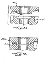
- Figs. 14 and 15 illustrate an alternative embodiment of the invention.
- component part 31' includes an interfering portion 60, which is defined by a wall portion that is sized to interfere with an engaging wall portion 61 of the mating component part 41'.
- the two component parts 31', 41' may be ultrasonically welded together to form the green assembly 50' illustrated in Fig. 14 , with the interfering material of the interfering portion 60 being melted and deformed during the welding step.
- the green body is debound and sintered in accordance with conventional metal powder molding techniques or other techniques that may be found suitable.
- the debinding of the green assembly may comprise catalytic debinding, alone or in conjunction with thermal debinding.
- the debound green assembly then is sintered at a conventional or otherwise suitable temperature to form a metal body.
- the green assembly will shrink or otherwise deform during sintering, and thus the metal part ultimately obtained will be measurably smaller or differently shaped than the green assembly from which it was prepared.
- the metal body thus formed Upon sintering, the metal body thus formed will be hermetically sealed along the ultrasonically welded junctures.
- the air chamber 25 of the nozzle 20 thus is hermetically sealed, except at the air inlet and outlets where it is desired to allow the passage of air.
- the invention provides a process that is used to prepare hermetically sealed hollow metal fluid flow nozzles.
Landscapes
- Engineering & Computer Science (AREA)
- Manufacturing & Machinery (AREA)
- Mechanical Engineering (AREA)
- Chemical & Material Sciences (AREA)
- Composite Materials (AREA)
- Materials Engineering (AREA)
- Powder Metallurgy (AREA)
- Pressure Welding/Diffusion-Bonding (AREA)
Description
- The invention is in the field of metal powder molding, and pertains more specifically to a method for preparing a metal body via metal powder molding techniques.
- It is known to make metal objects by means of metal powder molding techniques. In accordance with such techniques, a mixture of metal powder and a resinous binder is molded into a green body, typically by injection molding. The green body is then chemically or thermally debound, and is then sintered at a temperature near the melting temperature of the metal powder. Upon sintering of the green body, the metal powder particles fuse together to form a metal body. Numerous metal powder molding materials and techniques are known in the art, and such are exemplified in
U.S. Patent 5,401,292 (Japka) , entitled "Carbonyl Iron Powder Premix Composition" and inU.S. Patent 4,971,755 (Kawano et al.), entitled "Method for Preparing Powder Metallurgical Sintered Product." - When forming hollow metal objects using metal powder molding techniques, it is typical to mold two green halves or component parts of the metal object separately, and to then place these two component parts into contact with one another under pressure prior to debinding and sintering. One problem with known metal powder molding techniques is that it is difficult and often impossible to attain a hermetic seal between the two moulded component parts in the metal body. Thus, it is not presently commercially practicable to fabricate hermetically sealed hollow metal bodies, such as pressure vessels and fluid flow nozzles, using known metal powder moulding techniques. The present invention is addressed to this drawback in the metal powder moulding art.
-
US 4 364 783 discloses the use of ultrasonic welding in a method of end-capping a tubular green body comprising sinterable beta alumina precursor particulate and sacrificial binder. -
US 3 056 912 discloses a method of ultrasonically welding together metal work pieces. - The present invention is based on the surprising discovery that a hermetic seal may be obtained between two component parts of a metal powder moulded body if the parts are ultrasonically welded to one another while still in the green state. While it is not intended to limit the invention to a particular theory of operation, it is believed that the ultrasonic welding causes a more intimate mixing of the metal powder and binder materials in the component parts, such that upon sintering a more uniform and intimate metal bond is formed between the two component parts than would be obtained absent the ultrasonic welding step. This bond, it is believed, results in a hermetic seal in the metal body in the region of the ultrasonic weld.
- In accordance with the invention, a process for preparing a hermetically sealed hollow metal fluid flow nozzle comprising the steps of: providing a first green component part comprising a moulded powder material;
providing a second green component part comprising a molded powder material;
placing said first and second component parts together; ultrasonically welding said first component part to said second component part to form an ultrasonic weld located between surfaces thereof to thereby form a green assembly;
debinding said green assembly; and
sintering said green assembly characterized by
said second component part being of molded metal powder material having a perimeter area comprising contact surfaces, said first component part being of molded metal powder material having a complimentary perimeter area comprising ultrasonic energy director surfaces that can be positioned into contacting relation with said contact surfaces of said second component part, said ultrasonic energy director surfaces being ribs of the first component part and said contact surfaces being wall portions of the second component part or said ultrasonic energy director surfaces being interfering portions of the first component part and said contact surfaces being wall portions of the second component part, positioning the ultrasonic energy director surfaces of said first component part in contact with contact surfaces of the second component, carrying out said ultrasonic welding step with said ultrasonic energy director surfaces in contacting relation with said contact surfaces to form said ultrasonic weld along each of the perimeter areas, and carrying out said debinding and sintering steps to form a metal part with a hermetically sealed metal joint along a juncture between said energy director surfaces with said contact surfaces formed by said ultrasonic weld. - This green bonding area preferably is greater than the area of the ultrasonic weld, to thereby provide a union in the metal body that is strong relative to the union in the region of the weld. The invention also encompasses a metal body prepared in accordance with the foregoing process.
- These and other features of the invention will be exemplified in the following drawings, in which
-
-
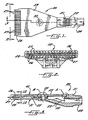
Figure 1 is a top view of a fluid flow nozzle made in accordance with the process of the invention. -
Figure 2 is an enlarged front elevational view of the fluid flow nozzle illustrated inFig. 1 . -
Figure 3 is an enlarged cross-sectional view of the illustrated nozzle taken in the plane of line 3-3 inFig. 1 . -
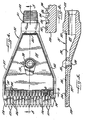
Figure 4 is a top view of a first green component part used to prepare the fluid flow nozzle illustrated inFig. 1 . -
Figure 5 is a cross-sectional view taken in the plane of line 5-5 inFig. 4 . -
Figure 6 is an enlarged cross-sectional view taken in the plane of line 6-6 inFig. 4 . -
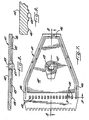
Figure 7 is a bottom view of a second green component part used to prepare the fluid flow nozzle illustrated inFig. 1 . -
Figure 8 is a cross-sectional view taken in the plane of line 8-8 inFig. 7 . -
Figure 9 is an enlarged cross-sectional view taken in the plane of line 9-9 inFig. 7 . -
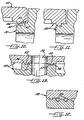
Figure 10 is a cross-sectional view, in the region corresponding to region A of the metal body shown inFig. 3 , of the first green component part shown inFigs. 4-6 and the second green component part shown inFigs. 7-9 immediately prior to ultrasonically welding. -
Figure 11 is a cross-sectional view of a green assembly formed upon ultrasonically welding together the component parts shown inFig. 10 . -
Figure 12 is a cross-sectional view, corresponding to a section in the plane of line 12-12 of the metal body shown inFig. 3 , of the green assembly formed by ultrasonically welding the first and second component parts. -
Figure 13 is a cross-sectional view, in the region corresponding to region B of the metal body shown inFig. 3 , of the green assembly. -
Figure 14 is a cross-sectional view of an alternative embodiment of a green assembly formed by ultrasonically welding two green component parts. -
Figure 15 is a cross-sectional view of the green component parts used to prepare the green assembly shown inFig. 14 . - While the invention is susceptible of various modifications and alternative constructions, certain illustrated embodiments thereof have been shown in the drawings and will be described below in detail. It should be understood, however, that there is no intention to limit the invention to the specific forms disclosed. But on the contrary, the intention is to cover all modifications falling within the scope of the claims.
- The present invention contemplates the preparation of metal parts using metal powder molding feedstocks. Numerous such materials are known in the art, and such materials are exemplified in the aforementioned U.S. Patents 5,401,292 and 4,971,755.
- The preferred metal powder molding material is CATAMOLD® 316L, sold by BASF AG, Ludwigshaffen, Germany. Other CATAMOLD® feedstocks also are useful in conjunction with the invention. The CATAMOLD® products are substantially homogeneous mixtures of fine metal powders, typically stainless steels, bound in a polyacetal binder. In accordance with known metal powder molding techniques, the feedstock of such metal powder molding material is molded, typically by injection molding, to form a green body. Suitable injecting molding conditions are disclosed in BASF publication CATAMOLD® Feedstock For Powder Injection Molding: Processing-Properties-Application, BASF Aktiengesellschaft, September 19, 1997.
- Turning now more particularly to the drawings, there is shown an illustrative
air flow nozzle 20 that embodies one example of a metal fluid flow nozzle prepared in accordance with the present inventive process. With reference toFigs. 1-3 , thenozzle 20 includes anupstream end 21 having a threadedportion 22 for connection to a supply line 24 (shown in phantom inFig. 1 ). Theupstream end 21 defines an air inlet passage that communicates with an internal air chamber 25 (shown inFig. 3 ) defined by abody portion 23 of the nozzle. Theair chamber 25 fluidically communicates with a multiplicity of air outlet passages 26 (shown inFigs. 2 and 3 ) disposed at thedownstream end 28 of thenozzle 20. Each of theair outlet passages 26 is bounded by a pair of flow baffles 27 (best shown inFig. 2 ). Thenozzle 20 further includes a cylindrical mounting bore 30 that extends through theinternal air chamber 25. - The
nozzle 20 is formed of a plurality of component parts which are connected to one another while still in the green state. In the illustrated embodiment, thenozzle 20 is formed from two component parts, namely first andsecond component parts first component part 31, depicted inFigs. 4-6 in a green state, comprises abody portion 37 formed with arecess 38 for defining a portion of theair chamber 25 in the finished nozzle and abore 39 for defining a portion of thethrough bore 30 in the finished nozzle. Thecomponent part 31 further is defined by a perimeter ormating area 32 designed to mate with a complementary perimeter area of the second component part (shown inFigs. 7-9 in the green state), as well as an annularbore mating area 39 andfront mating areas 34. - The
second component part 41, shown in a green state inFigs. 7-9 , includes a body portion 42 formed with arecess 45 for defining an opposing side of theair chamber 25 and abore 43 designed to join with and communicate with thebore 39 in the upper component part. Thesecond component part 41 further is formed with perimeter ormating areas - It will be appreciated that the component parts must be assembled and mated with a hermetic seal that prevents air from escaping through the seams between the parts in the finished nozzle when the nozzle is in use. The hermetic seal should be such as to prevent air or other fluid from escaping through the seams between the joined parts at the pressure expected to be encountered in service of the metal part. For example, for the illustrated
fluid flow nozzle 20, the hermetic seal should be able to withstand air at a pressure of at least about 15 psig. Heretofore, in products made with such molded components, it has not been possible to achieve reliable hermetic seals with a strength sufficient to withstand such operating pressures. - In accordance with the invention, the green component parts are assembled together and ultrasonically welded along their mating surfaces in order to form a unitary green assembly, which is then debound and sintered to form a metal body having a hermetically sealed union at each of the ultrasonic junctures. In the illustrated embodiment, the
component parts mating surface areas mating areas 33, 47 which surround and define the bore portions, and thefront mating areas - In keeping with the invention, the mating surface areas of at least one of the component parts are formed with energy directors, which cooperate with mating areas of the opposing component part to enhance the formation of ultrasonic welds between the parts during ultrasonic welding. In the illustrated embodiment, the
first component part 31 includes a plurality of ultrasonic energy director surfaces, which, in the illustrated embodiment, constitute aperimeter rib 32, an annular rib 33 surrounding thebore 39, and a series offront ribs 34. As shown more particularly inFigs. 5 and 6 , each of the ribs preferably has a substantially triangular cross section, although those skilled in the art of ultrasonic welding will appreciate that such ribs may take any other suitable shape. The outwardly projectingflat surfaces first component part 31. -
Fig. 10 illustrates thecomponent parts contact surface 46. Upon ultrasonically welding the parts to one another, the green assembly 50 (shown inFig. 11 ) is formed. Other portions of thegreen assembly 50 are illustrated inFigs. 12 and 13 . The ultrasonically welded portions of the green body generally define a welded area, which may be defined as that portion of the contact surface on thepart 41 that is taken up by the ultrasonic weld to theother component part 31. - In carrying out a further aspect of the invention, for enhancing the strength of the union between the component parts in the finished product, the mating areas of the component parts further have mutually engaging bonding surfaces which preferably are parallel and spaced apart when the energy director surface is placed into contact with the contact surface of the other component part. The ultrasonic welding of the parts to one another will cause deformation due to the melting of the material of the energy director surface. Thus, the bonding surfaces, exemplified by surfaces 51, 52 in
Fig. 10 , are brought into contact with or close proximity to one another once the first component part has been welded to the second component part to thereby define a green bonding area, or surface area of mutual contact or overlap. This green bonding area desirably is greater than the welded area defined by the ultrasonic weld, such that, when the green assembly is debound and sintered, the union of the component parts in the green bonding area is stronger than the union created by the ultrasonic weld.Fig. 13 illustrates another ultrasonic weld 53 and adjacent bonding areas 56 and 57. -
Figs. 14 and 15 illustrate an alternative embodiment of the invention. As shown inFig. 15 , component part 31' includes an interferingportion 60, which is defined by a wall portion that is sized to interfere with anengaging wall portion 61 of the mating component part 41'. The two component parts 31', 41' may be ultrasonically welded together to form the green assembly 50' illustrated inFig. 14 , with the interfering material of the interferingportion 60 being melted and deformed during the welding step. - In either embodiment of the invention, once the green body has been formed, it is debound and sintered in accordance with conventional metal powder molding techniques or other techniques that may be found suitable. For example, when the green assembly is formed from CATAMOLD® feedstock, the debinding of the green assembly may comprise catalytic debinding, alone or in conjunction with thermal debinding. After debinding of the green assembly, the debound green assembly then is sintered at a conventional or otherwise suitable temperature to form a metal body. Typically, the green assembly will shrink or otherwise deform during sintering, and thus the metal part ultimately obtained will be measurably smaller or differently shaped than the green assembly from which it was prepared.
- Upon sintering, the metal body thus formed will be hermetically sealed along the ultrasonically welded junctures. With regard to the illustrated embodiment of the invention, the
air chamber 25 of thenozzle 20 thus is hermetically sealed, except at the air inlet and outlets where it is desired to allow the passage of air. - Thus, it is seen the invention provides a process that is used to prepare hermetically sealed hollow metal fluid flow nozzles.
Claims (7)
- A process for preparing a hermetically sealed hollow metal fluid flow nozzle (20) comprising the steps of: providing a first green component part (31) comprising a moulded powder material;
providing a second green component part (41) comprising a molded powder material;
placing said first and second component parts (31, 41) together; ultrasonically welding said first component part (31) to said second component part (41) to form an ultrasonic weld (53) located between surfaces thereof to thereby form a green assembly (50);
debinding said green assembly (50); and
sintering said green assembly (50) characterized by
said second component part (41) being of molded metal powder material having a perimeter area comprising contact surfaces (46,47,48), said first component part (31) being of molded metal powder material having a complimentary perimeter area comprising ultrasonic energy director surfaces (32,33,34) that can be positioned into contacting relation with said contact surfaces (46,47,48) of said second component part (41), said ultrasonic energy director surfaces being ribs (32, 33, 34) of said first component part (31) and said contact surfaces being wall portions (61) of the second component part (41), or said ultrasonic energy director surfaces being interfering portions (60) of the first component part (31') and said contact surfaces being wall portions (61) of the second component part (41'), positioning the ultrasonic energy director surfaces (32,33,34) of said first component part (31) in contact with contact surfaces (46, 47, 48) of the second component (41'), carrying out said ultrasonic welding step with said ultrasonic energy director surfaces (32, 33, 34) in contacting relation with said contact surfaces (46,47,48) to form said ultrasonic weld (53) along each of the perimeter areas, and carrying out said debinding and sintering steps to form a metal part (20) with a hermetically sealed metal joint along a juncture between said ultrasonic energy director surfaces (32, 33, 34) with said contact surfaces (46,47,48) formed by said ultrasonic weld (53). - A process according to claim 1, in which said ribs (32, 33, 34) have a generally triangular cross section.
- A process according to claim 1, in which said interfering portion (60) are defined by wall portions sized to be in interfering engagement with wall portions (61) of said second component part (41).
- A process according to claim 1, said first and second parts (31, 41) having mutually engaging bonding surfaces (51, 52, 56, 57) which define a green bonding area upon ultrasonically welding said first component part (31) to said second component part (41).
- A process according to claim 4, said weld defining a welded area (51), said green bonding area (51, 52, 56, 57) being greater than said welding area (51).
- A process according to claim 1, wherein said debinding comprises thermal debinding.
- The process of claim 1, including providing said first green component part (31) by moulding the part from the metal powder material, and providing said second green component part (41) by moulding the part from the metal powder material.
Priority Applications (1)
| Application Number | Priority Date | Filing Date | Title |
|---|---|---|---|
| DE60131308T DE60131308T3 (en) | 2000-02-07 | 2001-01-25 | Method for producing a powder metal body with hermetic sealing |
Applications Claiming Priority (2)
| Application Number | Priority Date | Filing Date | Title |
|---|---|---|---|
| US09/498,673 US6228508B1 (en) | 2000-02-07 | 2000-02-07 | Process for preparing a metal body having a hermetic seal |
| US498673 | 2000-02-07 |
Publications (4)
| Publication Number | Publication Date |
|---|---|
| EP1122007A2 EP1122007A2 (en) | 2001-08-08 |
| EP1122007A3 EP1122007A3 (en) | 2002-08-14 |
| EP1122007B1 EP1122007B1 (en) | 2007-11-14 |
| EP1122007B2 true EP1122007B2 (en) | 2012-08-01 |
Family
ID=23982031
Family Applications (1)
| Application Number | Title | Priority Date | Filing Date |
|---|---|---|---|
| EP01300670A Expired - Lifetime EP1122007B2 (en) | 2000-02-07 | 2001-01-25 | Process for preparing a powder metal body having a hermetic seal |
Country Status (4)
| Country | Link |
|---|---|
| US (1) | US6228508B1 (en) |
| EP (1) | EP1122007B2 (en) |
| JP (1) | JP2001303108A (en) |
| DE (1) | DE60131308T3 (en) |
Families Citing this family (14)
| Publication number | Priority date | Publication date | Assignee | Title |
|---|---|---|---|---|
| JP2003326196A (en) * | 2002-05-13 | 2003-11-18 | Denso Corp | Ejector |
| US7172350B2 (en) | 2003-01-09 | 2007-02-06 | Korea Chemical Co., Ltd. | Forming method using thermal transfer printing sheet |
| US8668797B2 (en) | 2004-07-23 | 2014-03-11 | Lmt Mercer Group Inc. | Method of assembly of thermoplastic fencing |
| US20060033091A1 (en) * | 2004-07-23 | 2006-02-16 | Lmt Mercer Group Inc. | Thermoplastic fencing construction and method of assembly thereof |
| US7204898B2 (en) * | 2004-07-23 | 2007-04-17 | Lmt Mercer Group Inc. | Thermoplastic fencing construction and method of assembly thereof |
| US20070000128A1 (en) * | 2005-06-30 | 2007-01-04 | Brp Us Inc. | Fuel injector nozzle manufacturing method |
| DE102007024245B3 (en) * | 2007-05-15 | 2008-08-28 | Lechler Gmbh | Spray nozzle i.e. high pressure nozzle for descaling steel products, has outlet clamping curved surface, and another surface abutting against boundary of outlet in radial direction at specific angle to central longitudinal axis |
| US10226818B2 (en) * | 2009-03-20 | 2019-03-12 | Pratt & Whitney Canada Corp. | Process for joining powder injection molded parts |
| DE102012203339A1 (en) | 2012-03-02 | 2013-09-05 | Lechler Gmbh | Method for manufacturing green element for fluid nozzle, involves pressing heated stamper in components, and partially melting and welding components in one of parting line and stamper adjacent area |
| US9970318B2 (en) | 2014-06-25 | 2018-05-15 | Pratt & Whitney Canada Corp. | Shroud segment and method of manufacturing |
| RU2630142C1 (en) * | 2016-11-30 | 2017-09-05 | федеральное государственное автономное образовательное учреждение высшего образования "Национальный исследовательский Томский политехнический университет" (НИ ТПУ) | Method of producing metallic fidstock |
| CN106975753A (en) * | 2017-03-16 | 2017-07-25 | 东莞市依诺电子科技有限公司 | 3D printing processing method for metal material thin-wall structure part |
| US11864943B2 (en) | 2018-10-05 | 2024-01-09 | 3M Innovative Properties Company | Metal injection molding for stethoscope chestpiece |
| RU2701228C1 (en) * | 2019-06-17 | 2019-09-25 | Общество с ограниченной ответственностью "Передовые порошковые технологии" (ООО "Передовые порошковые технологии") | Thermoplastic granulated material (feedstock) and method of its production |
Citations (4)
| Publication number | Priority date | Publication date | Assignee | Title |
|---|---|---|---|---|
| US4618516A (en) † | 1985-09-12 | 1986-10-21 | Branson Ultrasonics Corporation | Ultrasonic welding of thermoplastic workpieces |
| US4722824A (en) † | 1986-06-04 | 1988-02-02 | Fine Particle Technology Corp. | Method of joining green bodies prior to sintering |
| US5426411A (en) † | 1993-04-23 | 1995-06-20 | Gould Electronics Inc. | Current limiting fuse |
| JPH11315564A (en) † | 1998-12-04 | 1999-11-16 | Toto Ltd | Joined products |
Family Cites Families (12)
| Publication number | Priority date | Publication date | Assignee | Title |
|---|---|---|---|---|
| US3056192A (en) * | 1957-12-30 | 1962-10-02 | Sonobond Corp | Vibratory welding process and apparatus |
| US4191654A (en) * | 1978-07-06 | 1980-03-04 | Pharmaco, Inc. | Device for holding membrane filter |
| US4364783A (en) * | 1981-09-08 | 1982-12-21 | Ford Motor Company | Ultrasonic end-capping of beta"-alumina tubes |
| FR2555159B1 (en) * | 1983-11-21 | 1986-06-27 | Ceraver | METHOD FOR WELDING TWO HOLLOW CERAMIC HALF PIECES, AND WELDING MACHINE FOR CARRYING OUT THE METHOD |
| JPS62195849A (en) * | 1986-02-20 | 1987-08-28 | Japan Storage Battery Co Ltd | Sealing of enclosed type storage battery |
| DE3611910A1 (en) * | 1986-04-09 | 1987-10-15 | Schaeffler Waelzlager Kg | IMPELLER FOR A RADIAL PUMP |
| JP2654973B2 (en) * | 1988-08-04 | 1997-09-17 | 株式会社トーキン | Manufacturing method of sintered article |
| US4971755A (en) | 1989-03-20 | 1990-11-20 | Kawasaki Steel Corporation | Method for preparing powder metallurgical sintered product |
| US5401292A (en) | 1992-08-03 | 1995-03-28 | Isp Investments Inc. | Carbonyl iron power premix composition |
| DE4332310C1 (en) * | 1993-09-23 | 1994-10-20 | Heraeus Kulzer Gmbh | Syringe for the metered dispensing of viscous material, especially of dental material |
| JP2782495B2 (en) * | 1993-11-08 | 1998-07-30 | 菊池プレス工業株式会社 | Welding method of metal work |
| US5827418A (en) * | 1996-10-11 | 1998-10-27 | Hoefer Pharmacia Biotech, Inc. | Electrophoresis cassette |
-
2000
- 2000-02-07 US US09/498,673 patent/US6228508B1/en not_active Expired - Lifetime
-
2001
- 2001-01-25 EP EP01300670A patent/EP1122007B2/en not_active Expired - Lifetime
- 2001-01-25 DE DE60131308T patent/DE60131308T3/en not_active Expired - Lifetime
- 2001-02-07 JP JP2001031312A patent/JP2001303108A/en active Pending
Patent Citations (4)
| Publication number | Priority date | Publication date | Assignee | Title |
|---|---|---|---|---|
| US4618516A (en) † | 1985-09-12 | 1986-10-21 | Branson Ultrasonics Corporation | Ultrasonic welding of thermoplastic workpieces |
| US4722824A (en) † | 1986-06-04 | 1988-02-02 | Fine Particle Technology Corp. | Method of joining green bodies prior to sintering |
| US5426411A (en) † | 1993-04-23 | 1995-06-20 | Gould Electronics Inc. | Current limiting fuse |
| JPH11315564A (en) † | 1998-12-04 | 1999-11-16 | Toto Ltd | Joined products |
Non-Patent Citations (1)
| Title |
|---|
| "Joint Designs for Ultrasonic Welding", 1999, Sonics and Materials Inc, Newtown , CT06470 USA † |
Also Published As
| Publication number | Publication date |
|---|---|
| DE60131308T2 (en) | 2008-09-25 |
| DE60131308D1 (en) | 2007-12-27 |
| JP2001303108A (en) | 2001-10-31 |
| US6228508B1 (en) | 2001-05-08 |
| EP1122007A2 (en) | 2001-08-08 |
| EP1122007B1 (en) | 2007-11-14 |
| DE60131308T3 (en) | 2012-12-27 |
| EP1122007A3 (en) | 2002-08-14 |
Similar Documents
| Publication | Publication Date | Title |
|---|---|---|
| EP1122007B2 (en) | Process for preparing a powder metal body having a hermetic seal | |
| US6846412B2 (en) | Combination filter assembly | |
| JP2001303108A5 (en) | ||
| US2869221A (en) | Method of producing valve housings | |
| CN101421029A (en) | Mixing element for static mixer, static mixer and method of production of such a mixing element | |
| US20230158612A1 (en) | Techniques and assemblies for joining components using solid retainer materials | |
| KR100896831B1 (en) | Heater head member and manufacturing method thereof | |
| US20070000128A1 (en) | Fuel injector nozzle manufacturing method | |
| JP2002240096A (en) | Method for manufacturing pipe joint made of resin | |
| US6860526B2 (en) | Coupling structure for a hollow body | |
| US6592287B1 (en) | Self-fixtured joint assembly and its preparation | |
| CA1156808A (en) | Method for bonding sintered metal pieces | |
| US5678163A (en) | Method for making an airbag initiator | |
| US20040222193A1 (en) | Method for resistance welding/brazing a tube to a member | |
| AU2016203034B2 (en) | Method for forming tooling and fabricating parts therefrom | |
| CA2283722A1 (en) | Process for manufacturing hollow plastic objects | |
| CA1040898A (en) | High speed room temperature seam bonding of metal sheets | |
| AU2000277025A1 (en) | Improved container and method and apparatus for forming the container | |
| EP1263560A1 (en) | Improved container and method and apparatus for forming the container | |
| JP2001232688A (en) | Method for manufacturing hollow body made of synthetic resin and hollow body made of synthetic resin | |
| JP2006159682A (en) | Insert molding mold and resin molding insert molding method | |
| JPS60105892A (en) | Manufacture of tube body for heat pipe | |
| JP2006159681A (en) | Insert member to resin molded product and resin molded product with insert member | |
| JPH1134180A (en) | Hollow resin container and manufacturing method thereof | |
| JPH02208015A (en) | Heating cylinder |
Legal Events
| Date | Code | Title | Description |
|---|---|---|---|
| PUAI | Public reference made under article 153(3) epc to a published international application that has entered the european phase |
Free format text: ORIGINAL CODE: 0009012 |
|
| AK | Designated contracting states |
Kind code of ref document: A2 Designated state(s): AT BE CH CY DE DK ES FI FR GB GR IE IT LI LU MC NL PT SE TR |
|
| AX | Request for extension of the european patent |
Free format text: AL;LT;LV;MK;RO;SI |
|
| PUAL | Search report despatched |
Free format text: ORIGINAL CODE: 0009013 |
|
| AK | Designated contracting states |
Kind code of ref document: A3 Designated state(s): AT BE CH CY DE DK ES FI FR GB GR IE IT LI LU MC NL PT SE TR |
|
| AX | Request for extension of the european patent |
Free format text: AL;LT;LV;MK;RO;SI |
|
| RIC1 | Information provided on ipc code assigned before grant |
Free format text: 7B 22F 7/06 A, 7B 23K 20/10 B, 7B 23K 33/00 B |
|
| 17P | Request for examination filed |
Effective date: 20030213 |
|
| AKX | Designation fees paid |
Designated state(s): DE FR GB |
|
| 17Q | First examination report despatched |
Effective date: 20040526 |
|
| 17Q | First examination report despatched |
Effective date: 20040526 |
|
| GRAP | Despatch of communication of intention to grant a patent |
Free format text: ORIGINAL CODE: EPIDOSNIGR1 |
|
| GRAS | Grant fee paid |
Free format text: ORIGINAL CODE: EPIDOSNIGR3 |
|
| GRAA | (expected) grant |
Free format text: ORIGINAL CODE: 0009210 |
|
| AK | Designated contracting states |
Kind code of ref document: B1 Designated state(s): DE FR GB |
|
| REG | Reference to a national code |
Ref country code: GB Ref legal event code: FG4D |
|
| REF | Corresponds to: |
Ref document number: 60131308 Country of ref document: DE Date of ref document: 20071227 Kind code of ref document: P |
|
| ET | Fr: translation filed | ||
| PLBI | Opposition filed |
Free format text: ORIGINAL CODE: 0009260 |
|
| PLAX | Notice of opposition and request to file observation + time limit sent |
Free format text: ORIGINAL CODE: EPIDOSNOBS2 |
|
| 26 | Opposition filed |
Opponent name: LECHLER GMBH Effective date: 20080801 |
|
| PLAB | Opposition data, opponent's data or that of the opponent's representative modified |
Free format text: ORIGINAL CODE: 0009299OPPO |
|
| R26 | Opposition filed (corrected) |
Opponent name: LECHLER GMBH Effective date: 20080801 |
|
| PLAF | Information modified related to communication of a notice of opposition and request to file observations + time limit |
Free format text: ORIGINAL CODE: EPIDOSCOBS2 |
|
| PLBB | Reply of patent proprietor to notice(s) of opposition received |
Free format text: ORIGINAL CODE: EPIDOSNOBS3 |
|
| APBM | Appeal reference recorded |
Free format text: ORIGINAL CODE: EPIDOSNREFNO |
|
| APBP | Date of receipt of notice of appeal recorded |
Free format text: ORIGINAL CODE: EPIDOSNNOA2O |
|
| APAH | Appeal reference modified |
Free format text: ORIGINAL CODE: EPIDOSCREFNO |
|
| APBQ | Date of receipt of statement of grounds of appeal recorded |
Free format text: ORIGINAL CODE: EPIDOSNNOA3O |
|
| APBU | Appeal procedure closed |
Free format text: ORIGINAL CODE: EPIDOSNNOA9O |
|
| PUAH | Patent maintained in amended form |
Free format text: ORIGINAL CODE: 0009272 |
|
| STAA | Information on the status of an ep patent application or granted ep patent |
Free format text: STATUS: PATENT MAINTAINED AS AMENDED |
|
| 27A | Patent maintained in amended form |
Effective date: 20120801 |
|
| AK | Designated contracting states |
Kind code of ref document: B2 Designated state(s): DE FR GB |
|
| REG | Reference to a national code |
Ref country code: DE Ref legal event code: R102 Ref document number: 60131308 Country of ref document: DE |
|
| REG | Reference to a national code |
Ref country code: DE Ref legal event code: R102 Ref document number: 60131308 Country of ref document: DE Effective date: 20120801 |
|
| REG | Reference to a national code |
Ref country code: FR Ref legal event code: PLFP Year of fee payment: 16 |
|
| REG | Reference to a national code |
Ref country code: FR Ref legal event code: PLFP Year of fee payment: 17 |
|
| REG | Reference to a national code |
Ref country code: FR Ref legal event code: PLFP Year of fee payment: 18 |
|
| PGFP | Annual fee paid to national office [announced via postgrant information from national office to epo] |
Ref country code: FR Payment date: 20191216 Year of fee payment: 20 |
|
| PGFP | Annual fee paid to national office [announced via postgrant information from national office to epo] |
Ref country code: DE Payment date: 20200114 Year of fee payment: 20 Ref country code: GB Payment date: 20200115 Year of fee payment: 20 |
|
| REG | Reference to a national code |
Ref country code: DE Ref legal event code: R071 Ref document number: 60131308 Country of ref document: DE |
|
| REG | Reference to a national code |
Ref country code: GB Ref legal event code: PE20 Expiry date: 20210124 |
|
| PG25 | Lapsed in a contracting state [announced via postgrant information from national office to epo] |
Ref country code: GB Free format text: LAPSE BECAUSE OF EXPIRATION OF PROTECTION Effective date: 20210124 |