EP1121904B1 - Fixation member for treating orthopaedic fractures - Google Patents
Fixation member for treating orthopaedic fractures Download PDFInfo
- Publication number
- EP1121904B1 EP1121904B1 EP01300715A EP01300715A EP1121904B1 EP 1121904 B1 EP1121904 B1 EP 1121904B1 EP 01300715 A EP01300715 A EP 01300715A EP 01300715 A EP01300715 A EP 01300715A EP 1121904 B1 EP1121904 B1 EP 1121904B1
- Authority
- EP
- European Patent Office
- Prior art keywords
- fixation member
- bone
- body portion
- penetration
- fixation
- Prior art date
- Legal status (The legal status is an assumption and is not a legal conclusion. Google has not performed a legal analysis and makes no representation as to the accuracy of the status listed.)
- Expired - Lifetime
Links
- 210000000988 bone and bone Anatomy 0.000 claims abstract description 136
- 230000035515 penetration Effects 0.000 claims abstract description 77
- 239000012634 fragment Substances 0.000 description 29
- 230000000399 orthopedic effect Effects 0.000 description 21
- 230000035876 healing Effects 0.000 description 6
- 230000006378 damage Effects 0.000 description 5
- 230000007246 mechanism Effects 0.000 description 5
- 238000001356 surgical procedure Methods 0.000 description 5
- 230000017531 blood circulation Effects 0.000 description 4
- 230000036770 blood supply Effects 0.000 description 4
- 201000010099 disease Diseases 0.000 description 3
- 208000037265 diseases, disorders, signs and symptoms Diseases 0.000 description 3
- 239000000463 material Substances 0.000 description 3
- RTAQQCXQSZGOHL-UHFFFAOYSA-N Titanium Chemical compound [Ti] RTAQQCXQSZGOHL-UHFFFAOYSA-N 0.000 description 2
- 238000013459 approach Methods 0.000 description 2
- 239000008280 blood Substances 0.000 description 2
- 210000004369 blood Anatomy 0.000 description 2
- 230000001788 irregular Effects 0.000 description 2
- 230000000149 penetrating effect Effects 0.000 description 2
- 239000010936 titanium Substances 0.000 description 2
- 229910052719 titanium Inorganic materials 0.000 description 2
- 229910045601 alloy Inorganic materials 0.000 description 1
- 239000000956 alloy Substances 0.000 description 1
- 238000003780 insertion Methods 0.000 description 1
- 230000037431 insertion Effects 0.000 description 1
- 229910052751 metal Inorganic materials 0.000 description 1
- 239000002184 metal Substances 0.000 description 1
- 238000012986 modification Methods 0.000 description 1
- 230000004048 modification Effects 0.000 description 1
- 230000017074 necrotic cell death Effects 0.000 description 1
- 238000012829 orthopaedic surgery Methods 0.000 description 1
- 230000000087 stabilizing effect Effects 0.000 description 1
- 239000010935 stainless steel Substances 0.000 description 1
- 229910001220 stainless steel Inorganic materials 0.000 description 1
Images



Classifications
-
- A—HUMAN NECESSITIES
- A61—MEDICAL OR VETERINARY SCIENCE; HYGIENE
- A61B—DIAGNOSIS; SURGERY; IDENTIFICATION
- A61B17/00—Surgical instruments, devices or methods
- A61B17/56—Surgical instruments or methods for treatment of bones or joints; Devices specially adapted therefor
- A61B17/58—Surgical instruments or methods for treatment of bones or joints; Devices specially adapted therefor for osteosynthesis, e.g. bone plates, screws or setting implements
- A61B17/68—Internal fixation devices, including fasteners and spinal fixators, even if a part thereof projects from the skin
- A61B17/84—Fasteners therefor or fasteners being internal fixation devices
- A61B17/842—Flexible wires, bands or straps
-
- A—HUMAN NECESSITIES
- A61—MEDICAL OR VETERINARY SCIENCE; HYGIENE
- A61B—DIAGNOSIS; SURGERY; IDENTIFICATION
- A61B17/00—Surgical instruments, devices or methods
- A61B17/56—Surgical instruments or methods for treatment of bones or joints; Devices specially adapted therefor
- A61B17/58—Surgical instruments or methods for treatment of bones or joints; Devices specially adapted therefor for osteosynthesis, e.g. bone plates, screws or setting implements
- A61B17/68—Internal fixation devices, including fasteners and spinal fixators, even if a part thereof projects from the skin
- A61B17/80—Cortical plates, i.e. bone plates; Instruments for holding or positioning cortical plates, or for compressing bones attached to cortical plates
- A61B17/809—Cortical plates, i.e. bone plates; Instruments for holding or positioning cortical plates, or for compressing bones attached to cortical plates with bone-penetrating elements, e.g. blades or prongs
Definitions
- the present invention generally relates to an appliance for treating orthopedic injuries or disease.
- the present invention particularly relates to a fixation member configured to be utilized in orthopedic surgery for the treatment of periarticular orthopedic fractures.
- a periarticular plate is one type of appliance employed by physicians to treat certain types of orthopedic injuries.
- periarticular plates are used during orthopaedic surgery to engage and stabilize comminuted bone.
- Periarticular plates can also be used to distribute a load in osteopenic bone.
- periarticular plates are configured as flat pieces of titanium, surgical grade stainless steel, or other surgical grade alloys.
- a periarticular plate will typically have multiple holes defined therein such that the periarticular plate can be secured to a piece of bone and/or bone fragments with a number of screws. Once attached to comminuted bone in the above described manner, the periarticular plate functions to inhibit relative movement between bone fragments and thus enhances healing.
- periarticular plates enhance the healing of comminuted bone to some degree, they also suffer from a number of drawbacks.
- the flat "plate like” nature of these appliances result in a relatively large surface area of the periarticular plate being biased against the damaged bone. Having a relatively large surface area of the periarticular plate biased against the damaged bone can occlude or otherwise inhibit blood flow to some areas of the bone and thus delay healing. In extreme cases, necrosis may result from the aforementioned occlusion.
- the flat "plate like" configuration of periarticular plates results in these appliances having a somewhat limited ability to actually inhibit the relative movement between bone fragments. The use of multiple screws to attach the periarticular plate to the bone fragments helps to alleviate the aforementioned problem, however, in many instances the bone fragments are too small or brittle to withstand the insertion of one or more screws.
- WO-A-9938447 discloses a fixation device comprising a plate which is arcuate when viewed along its length so that it can be fitted around the bone.
- the fixation device has an array of fastening fingers, each having fastening projections, along each of its opposite edges.
- the device also has a number of inwardly extending depressions formed in the body of the device which engage the surface of the bone in order to maintain a gap between the bone and the internal surface of the body of the device.
- depressions inhibit blood flow to the areas of the bone where the depressions engage the surface of the bone and restrict blood flow between the body of the device and the bone.
- a fixation member for treating orthopedic fractures.
- the fixation member includes a body portion having (i) an upper surface, (ii) a lower surface, and (iii) a perimeter edge interposed between the upper surface and the lower surface.
- the fixation member also includes a number of arm members each having a first end and a second end. The first end of each arm member being secured to the perimeter edge such that each arm member extends in a radial direction relative to the body portion.
- the fixation member further includes a plurality of penetration structures secured to the second end of each arm member such that each penetration structure extends in an axial direction relative to the body portion.
- the penetration structure is configured so as to penetrate below an outer surface of a bone when the fixation member is biased against the outer surface of the bone.
- the penetration structure is further configured to limit the penetration so that the lower surface of the body portion is prevented from contacting the outer surface of the bone when the fixation member is biased against the outer surface of the bone.
- the penetration structure is defined by a first substantially triangular shaped wall segment, a second substantially triangular shaped wall segment, a third substantially triangular wall segment, and a fourth substantially triangular shaped wall segment secured together so as to form a pyramid structure having a base and an apex.
- the pyramid structure has a width W 1 and a thickness T 1 , and the width W 1 and the thickness T 1 of the pyramid structure increase from the apex to the base.
- a fixation member for treating orthopedic fractures.
- the fixation member includes a body portion having (i) an upper surface, (ii) a lower surface, (iii) a perimeter edge interposed between the upper surface and the lower surface, and (iv) a fastener hole defined therein.
- the fixation member also includes a number of arm members each having a first end and a second end, the first end of each arm member being secured to the perimeter edge such that (i) each arm member extends in a radial direction relative to a perpendicular central axis of the body portion and (ii) the arm members are spaced apart from one another along the perimeter edge such that a notch is defined between adjacent arm members.
- the fixation member also includes a penetration structure secured to each arm member such that each penetration structure extends in an axial direction relative to the perpendicular central axis of the body portion.
- Each penetration structure is (i) configured so as to penetrate below an outer surface of a bone when the fixation member is biased against the outer surface of the bone and (ii) further configured to limit the penetration so that the lower surface of the body portion is prevented from contacting the outer surface of the bone when the fixation member is biased against the outer surface of the bone.
- the fixation member for treating orthopedic fractures.
- the fixation member includes a body portion having (i) an upper surface, (ii) a lower surface, (iii) a perimeter edge interposed between the upper surface and the lower surface, and (iv) a fastener hole defined therein.
- the fixation member also includes a first arm member having a length L 1 .
- the first arm member is secured to the perimeter edge such that the first arm member extends in a radial direction relative to the body portion.
- the fixation member also includes a second arm member having a length L 2 which is greater than length L 1 .
- the second arm member is secured to the perimeter edge such that the second arm member extends in a radial direction relative to the body portion.
- the fixation member further includes a first penetration structure secured to the first arm member such that the first penetration structure extends in an axial direction relative to the body portion.
- the fixation member also includes a second penetration structure secured to the second arm member such that the second penetration structure extends in an axial direction relative to the body portion.
- the first penetration structure and the second penetration structure are both configured so as to penetrate below an outer surface of a bone when the fixation member is biased against the outer surface of the bone.
- the first penetration structure and the second penetration structure are both further configured to limit the penetration so that the lower surface of the body portion is prevented from contacting the outer surface of the bone when the fixation member is biased against the outer surface of the bone.
- the fixation member for treating orthopedic fractures.
- the fixation member includes a body portion having (i) an upper surface, (ii) a lower surface, and (iii) a perimeter edge interposed between the upper surface and the lower surface.
- the fixation member also includes a number of arms secured to and extending outward from the perimeter edge of the body portion in a radial direction.
- the fixation member also includes a penetration structure secured to each of the arm members such that each penetration structure extends in an axial direction relative to the body portion.
- Each of the penetration structures is configured so as to penetrate below an outer surface of a bone when the fixation member is biased against the outer surface of the bone.
- the fixation member also includes a stop member connected to the body portion. The stop member is configured to limit the penetration of the penetration structures so that the lower surface of the body portion is prevented from contacting the outer surface of the bone when the fixation member is biased against the outer surface of the bone.
- the fixation member for treating orthopedic fractures.
- the fixation member includes a body portion and a number of arm members secured to and extending outward from the body portion.
- the fixation member also includes a penetration structure secured to each of the arm members which is configured to penetrate below an outer surface of a bone when the fixation member is biased against the outer surface of the bone.
- the fixation member further includes a stop member connected to the body portion. The stop member is configured to limit the penetration of the penetration structures when the fixation member is biased against an outer surface of the bone.
- apparatus 10 which incorporates the features of the present invention therein.
- apparatus 10 can be utilized to immobilized bone fragments 14 of a comminuted bone 12 (hereinafter referred to as bone 12).
- apparatus 10 includes a fixation member 16, a fixation member 18, screws 20, and a k-wire 22.
- fixation member 16 includes a number of arm members 32, a stop member 46, penetration structures 42, and a body portion 24.
- Body portion 24 has a fastener hole 52 and a wire hole 66 defined therein.
- Body portion 24 also has an upper surface 26, a lower surface 28, and a perimeter edge 30 interposed between upper surface 26 and lower surface 28. It should be understood that while body portion 24 is shown as being substantially annular shaped, other shapes are contemplated. For example, body portion 24 could be square shaped or have an oblong shape.
- each arm member 32 has an end 34 secured to perimeter edge 30 of body portion 24 so that each arm member 32 extends outwardly in a radial direction relative to a perpendicular central axis 38 of body portion 24. Moreover, arm members 32 are spaced apart from one another along perimeter edge 30 such that a notch 40 is defined between adjacent arm members 32. It should be appreciated that arm members 32 can have various lengths. For example, as shown in FIG. 10, arm member 32a has a length L 1 which is greater than the length L 2 of arm member 32b. Having arm members 32 of various lengths is an advantage of the present invention since it enhances the ability of fixation member 16 to reach and stabilize a greater surface area of comminuted bone 12 (see FIG. 1). In other words , the aforementioned advantage allows arm members 32 of fixation member 16 to reach, contact, and thus and stabilize, a greater number of bone fragments 14 (see FIGS. 1 and 2) in comminuted bone 12.
- fixation member 16 (including arm members 32) is preferably made from a material having a relatively low elastic modulus.
- fixation member 16 can be made from titanium. Having fixation member 16 made from a low elastic modulus material allows fixation member 16 to slightly bend or flex when biased against an outer surface 44 of bone 12 with a fastener, such as screw 20 (see FIGS. 1 and 2).
- the above described notches 40 enhance the ability of arm members 32 to slightly bend or flex and thus further allow fixation member 16 to readily conform to the irregular surface features of bone 12.
- the above described ability to slightly flex allows fixation member 16 to readily conform to the irregular surface features of bone 12 and thus exert an equal pressure on outer surface 44 when biased against bone 12 with screw 20.
- the ability of fixation member 16 to slightly bend under a load ensures that penetration structures 42 remains in contact with bone 12 and thus substantially prevent relative movement between bone fragments 14.
- a penetration structure 42 is secured to an end 36 of each arm member 32 such that each penetration structure 42 extends in an axial direction relative to perpendicular central axis 38 of body portion 24.
- Each penetration structure 42 is configured so as to penetrate below outer surface 44 of bone 12 when fixation member 16 is biased against outer surface 44 of bone 12.
- each penetration structure 42 is further configured so as to limit the aforementioned penetration such that lower surface 28 of body portion 24 is prevented from contacting outer surface 44 of bone 12 (see FIGS. 1 and 2) when fixation member 16 is biased against outer surface 44 of bone 12.
- Each penetration structure 42 is configured to be defined by substantially triangular shaped wall segments 68, 70, 72, and 74.
- substantially triangular shaped wall segments 68, 70, 72, and 74 are secured together so as to form a pyramid structure 76 having a base 78 and an apex 80.
- Pyramid structure 76 has a width W 1 (see FIG. 16) and a thickness T 1 (see FIG. 17). It should be appreciated that width W 1 and thickness T 1 of pyramid structure 76 both increase moving along the direction from apex 80 to base 78. Having the width W 1 and the thickness T 1 of pyramid structure 76 increase from apex 80 to base 78 serves two purposes.
- this configuration functions to allow each penetration structure 42 to penetrate below outer surface 44 of bone 12 to a certain degree when fixation member 16 is biased against outer surface 44 of bone 12.
- the aforementioned configuration also functions to limit the amount each penetration structure 42 can penetrate below outer surface 44 of bone 12.
- a penetration structure 42 is urged against outer surface 44 of bone 12 (for example with screw 20)
- apex 80 of pyramid structure 76 is advanced through outer surface 44 so as to create a hole (not shown) therein.
- penetration structure 42 becomes embedded in, or penetrates into, bone 12 such that a portion of each substantially triangular shaped wall segment 68, 70, 72, and 74 comes into contact with bone tissue.
- each penetration structure 42 can penetrate below outer surface 44 of bone 12 in the above described manner ensures that lower surface 28 of body portion 24 is prevented from contacting outer surface 44 of bone 12 when fixation member 16 is biased against outer surface 44 of bone 12.
- penetration structures 42 configured such that they only penetrate outer surface 44 of bone 12 to a limited degree is an important aspect of the present invention.
- the piercing of penetration structures 42 into outer surface 44 of bone 12 ensures that arm members 32 of fixation member 16 remain securely attached to bone fragments 14.
- Having arm members 32 securely attached to bone fragments 14 ensures that fixation member 16 functions to effectively inhibit relative movement between bone fragments 14 and thus enhances the healing of bone 12.
- limiting the penetration of penetration structures 42 ensures that a space 122 (see Fig. 2) is maintained between outer surface 44 of bone 12 and lower surface 28 of body portion 24.
- space 122 interposed between outer surface 44 and lower surface 28 ensures that an adequate blood supply is provided to bone 12. Ensuring that at an adequate blood supply is provided to bone 12 also enhances the healing of bone 12.
- fastener hole 52 has an edge 58 and a center as illustrated by center line 56.
- Edge 58 includes a convex wall portion 60 which extends towards center line 56.
- Convex wall portion 60 is configured to contact a convex wall segment 124 defined on screw 20 (see FIG. 2) when screw 20 is inserted through fastener hole 52 and utilized to secure fixation member 16 to bone 12.
- Having convex wall portion 60 serve as a bearing surface for convex wall segment 124 reduces the contact surface area between screw 20 and edge 58 as compared to having a flat edge acting as a bearing surface for a flat screw wall segment. Reducing the contact surface area between screw 20 and edge 58 reduces the probability that small pieces of metal or other material will be sheared off of edge 58 or convex wall segment 124 as screw 20 is rotated relative to, and biased against, edge 58.
- edge 58 further includes a land portion 62 secured to a lower end 64 of convex wall portion 60. Land portion 62 enhances the structural strength of body portion 24 in the area surrounding fastener hole 52.
- fastener hole 52 is eccentrically located relative to perpendicular central axis 38 of body portion 24. Having faster hole 52 eccentrically located relative to perpendicular central axis 38 cooperates with other features of fixation member 16 so as to allow a surgeon to secure fixation member 16 to a relatively large bone fragment 14 with screw 20 while still being able to reach smaller bone fragments 14 with penetration structures 42.
- having (i) an eccentrically located fastener hole 52 and (ii) arm members 32 of varying lengths allows fixation member 16 to be secured to a relatively large bone fragment 14 while still allowing penetration structures 42 to reach and secure relatively small bone fragments 16.
- wire hole 66 is defined in body portion 24 such that wire hole 66 is spaced apart from fastener hole 52.
- Wire hole 66 is configured so that wire 22 can be inserted through wire hole 66 in a well known manner so as to stabilize fixation member 16 prior to securing fixation member 16 to bone 12 with screw 20.
- stop member 46 is connected to lower surface 28 of body portion 24. Stop member 46 is also configured to limit the penetration of penetration structures 42 so that lower surface 28 of body portion 24 is prevented from contacting outer surface 44 of bone 12 when fixation member 16 is biased against outer surface 44 of bone 12.
- stop member 46 is an annular ridge 48 secured to a lower edge 127 of land portion 62 such that annular ridge 48 extends away from lower surface 28 of body portion 24. (Note securing annular ridge 48 in the above described manner results in annular ridge 48 being in a concentric relationship with fastener hole 52.)
- stop member 46 are contemplated.
- Stop member 46 functions to prevent lower surface 28 of body portion 24 from coming into contact with outer surface 44 of bone 12 in the following manner. As fixation member 16 is urged against outer surface 44 of bone 12 (for example with screw 20), lower surface 28 is advanced toward outer surface 44 until an end surface 50 of annular ridge 48 contacts outer surface 44 of bone 12 whereupon the advancement of lower surface 28 toward outer surface 44 is stopped. Since annular ridge 48 extends outwardly from lower surface 28 a certain distance, space 122 is maintained between lower surface 28 and outer surface 44 of bone 12. Therefore, it should be appreciated that stop member 46 also prevents body portion 24 from coming into contact with outer surface 44 of bone 12 and thus ensures that an adequate blood supply is provided to bone 12.
- stop member 46 can be disposed on other areas of fixation member 16.
- a stop member 46 can be disposed on penetration structures 42.
- a stop member 46 could be disposed on each arm member 32 if desired.
- stop member 46 could be configured as a ridge extending from arm members 32. In this configuration a ridge is interposed between each penetration structure 42 and body portion 24 so as to limit the penetration of penetration structures 42.
- fixation member 16 can be equipped with both (i) penetration structures 42 and (ii) stop member 46 so these elements can cooperate to prevent lower surface 28 of body portion 24 from coming into contact with outer surface 44 of bone 12.
- fixation member 16 can also be equipped with just penetration structures 42, or just stop member 46, since either one of these elements are sufficient to prevent lower surface 28 of body portion 24 from coming into contact with outer surface 44 of bone 12.
- fixation members 18, 92, and 110 which can be used in the present invention.
- the aforementioned fixation members are substantially similar to fixation member 16.
- the aforementioned fixation members function, and have the same advantages, as discussed above with regard to fixation member 16.
- fixation members 18, 92, and 110 can be substituted for fixation member 16, or be used in conjunction with fixation member 16. Therefore, only a relatively brief description of these fixation members is provided below.
- fixation member 18 includes a body portion 90 and a number of arm members 86.
- fixation member 18 has a fastener hole which is concentric with a perpendicular central axis 104.
- fixation member 18 is structurally different from fixation member 16 in that fixation member 18 has arm members 86 which are angled downward relative to body portion 90 in the direction indicated by arrow 129.
- fixation member 18 does not include a stop member such as ridge 48 discussed above.
- arm members 86 are angled relative to perpendicular central axis 104 such that a linear extension of a top surface 106 of arm members 86 defines an obtuse angle ⁇ between perpendicular central axis 104 and linear extension of top surface 106.
- fixation member 92 includes a body portion 94, a number of arm members 112, and a stop member 96 configured as an annular ridge 98.
- arm members 112 of fixation member 92 extend radially from body portion 94 in the direction indicated by arrow 100 such that a linear extension of a top surface 108 of each arm member 112 defines a right angle ⁇ between the linear extension and a perpendicular central axis 102.
- fixation member 110 includes a body portion 114, a number of arm members 120, and a stop member 116 configured as an annular ridge 118. Arm members 120 of fixation member 110 radially extend from body portion 114 as previously discussed above for fixation members 18, 92, and 16, however each arm member 120 of fixation member 110 has an arcuate shape.
- fixation member 110 may be utilized with a relatively large screw, while fixation members 18 and 92 can be utilized with a relatively small screw.
- apparatus 10 can be used in the following manner. Initially a surgeon places fixation member 16 in an appropriate location on outer surface 44 of bone 12. In particular, fixation member 16 is positioned so that penetration structures 42 contact several bone fragments 14. Once fixation member 16 is positioned, an end of wire 22 is advanced through wire hole 66 while the other end of wire 22 is inserted into bone 12. Utilizing wire 22 in the aforementioned manner stabilizes fixation member 16 until screw 20 is inserted through fastener hole 52 and screwed into a bone fragment 14. Screwing screw 20 into bone fragment 14 causes fixation member 16 to be urged against outer surface 44 of bone 12 so that penetration structures 42 penetrate outer surface 44 in the previously described manner.
- Screwing screw 20 into bone fragment 14 also causes stop member 46 to contact outer surface 44 of bone 12.
- both penetration structures 42 and stop member 46 function to ensure that space 122 is maintained between body portion 24 and outer surface 44 of bone 12. Therefore, fixation member 16 effectively stabilizes bone fragments 14 while ensuring that an adequate flow of blood is provided to bone 12.
- fixation member 16 can be used in conjunction with another fixation member, such as fixation member 18.
- Fixation member 18 is used in the same manner as described above for fixation member 16.
- wire 22 can be secured to both of the screws 20 used to fasten fixation members 16 and 18 so as to further stabilize bone fragments 14. Once both fixation members 16 and 18 are in place, wire 22 can be removed or left in place depending upon the surgeon's desire.
- the present invention provides fixation members which effectively stabilize bone fragments 14 of comminuted bone 12 without substantially occluding blood flow.
- the fixation members of the present invention are capable of stabilizing a plurality of bone fragments 14 without using a large number of screws 20.
- the fixation members of the present invention can stabilize a plurality of bone fragments 14 (including bone fragments 14 which are to small to have a screw 20 inserted therein) with the use of a single screw 20.
Landscapes
- Health & Medical Sciences (AREA)
- Orthopedic Medicine & Surgery (AREA)
- Surgery (AREA)
- Life Sciences & Earth Sciences (AREA)
- Heart & Thoracic Surgery (AREA)
- Animal Behavior & Ethology (AREA)
- Engineering & Computer Science (AREA)
- Biomedical Technology (AREA)
- Neurology (AREA)
- Medical Informatics (AREA)
- Molecular Biology (AREA)
- Nuclear Medicine, Radiotherapy & Molecular Imaging (AREA)
- General Health & Medical Sciences (AREA)
- Public Health (AREA)
- Veterinary Medicine (AREA)
- Surgical Instruments (AREA)
- Materials For Medical Uses (AREA)
- Orthopedics, Nursing, And Contraception (AREA)
Abstract
Description
- The present invention generally relates to an appliance for treating orthopedic injuries or disease. The present invention particularly relates to a fixation member configured to be utilized in orthopedic surgery for the treatment of periarticular orthopedic fractures.
- Physicians utilize various appliances to treat orthopedic conditions or injuries. For example, a periarticular plate is one type of appliance employed by physicians to treat certain types of orthopedic injuries. In particular, periarticular plates are used during orthopaedic surgery to engage and stabilize comminuted bone. Periarticular plates can also be used to distribute a load in osteopenic bone.
- Typically, periarticular plates are configured as flat pieces of titanium, surgical grade stainless steel, or other surgical grade alloys. In addition, a periarticular plate will typically have multiple holes defined therein such that the periarticular plate can be secured to a piece of bone and/or bone fragments with a number of screws. Once attached to comminuted bone in the above described manner, the periarticular plate functions to inhibit relative movement between bone fragments and thus enhances healing.
- While periarticular plates enhance the healing of comminuted bone to some degree, they also suffer from a number of drawbacks. For example, once attached to the bone, the flat "plate like" nature of these appliances result in a relatively large surface area of the periarticular plate being biased against the damaged bone. Having a relatively large surface area of the periarticular plate biased against the damaged bone can occlude or otherwise inhibit blood flow to some areas of the bone and thus delay healing. In extreme cases, necrosis may result from the aforementioned occlusion. In addition, the flat "plate like" configuration of periarticular plates results in these appliances having a somewhat limited ability to actually inhibit the relative movement between bone fragments. The use of multiple screws to attach the periarticular plate to the bone fragments helps to alleviate the aforementioned problem, however, in many instances the bone fragments are too small or brittle to withstand the insertion of one or more screws.
- WO-A-9938447 discloses a fixation device comprising a plate which is arcuate when viewed along its length so that it can be fitted around the bone. The fixation device has an array of fastening fingers, each having fastening projections, along each of its opposite edges. The device also has a number of inwardly extending depressions formed in the body of the device which engage the surface of the bone in order to maintain a gap between the bone and the internal surface of the body of the device. However, such depressions inhibit blood flow to the areas of the bone where the depressions engage the surface of the bone and restrict blood flow between the body of the device and the bone.
- Therefore, there is a need for an apparatus for treating periarticular orthopedic fractures which addresses one or more of the above described drawbacks.
- In accordance with one embodiment of the present invention, there is provided a fixation member for treating orthopedic fractures. The fixation member includes a body portion having (i) an upper surface, (ii) a lower surface, and (iii) a perimeter edge interposed between the upper surface and the lower surface. The fixation member also includes a number of arm members each having a first end and a second end. The first end of each arm member being secured to the perimeter edge such that each arm member extends in a radial direction relative to the body portion. The fixation member further includes a plurality of penetration structures secured to the second end of each arm member such that each penetration structure extends in an axial direction relative to the body portion. The penetration structure is configured so as to penetrate below an outer surface of a bone when the fixation member is biased against the outer surface of the bone. The penetration structure is further configured to limit the penetration so that the lower surface of the body portion is prevented from contacting the outer surface of the bone when the fixation member is biased against the outer surface of the bone.
- The penetration structure is defined by a first substantially triangular shaped wall segment, a second substantially triangular shaped wall segment, a third substantially triangular wall segment, and a fourth substantially triangular shaped wall segment secured together so as to form a pyramid structure having a base and an apex. The pyramid structure has a width W1 and a thickness T1, and the width W1 and the thickness T1 of the pyramid structure increase from the apex to the base.
- Pursuant to another embodiment of the present invention, there is provided a fixation member for treating orthopedic fractures. The fixation member includes a body portion having (i) an upper surface, (ii) a lower surface, (iii) a perimeter edge interposed between the upper surface and the lower surface, and (iv) a fastener hole defined therein. The fixation member also includes a number of arm members each having a first end and a second end, the first end of each arm member being secured to the perimeter edge such that (i) each arm member extends in a radial direction relative to a perpendicular central axis of the body portion and (ii) the arm members are spaced apart from one another along the perimeter edge such that a notch is defined between adjacent arm members. The fixation member also includes a penetration structure secured to each arm member such that each penetration structure extends in an axial direction relative to the perpendicular central axis of the body portion. Each penetration structure is (i) configured so as to penetrate below an outer surface of a bone when the fixation member is biased against the outer surface of the bone and (ii) further configured to limit the penetration so that the lower surface of the body portion is prevented from contacting the outer surface of the bone when the fixation member is biased against the outer surface of the bone.
- Pursuant to yet another embodiment of the present invention there is provided a fixation member for treating orthopedic fractures. The fixation member includes a body portion having (i) an upper surface, (ii) a lower surface, (iii) a perimeter edge interposed between the upper surface and the lower surface, and (iv) a fastener hole defined therein. The fixation member also includes a first arm member having a length L1. The first arm member is secured to the perimeter edge such that the first arm member extends in a radial direction relative to the body portion. The fixation member also includes a second arm member having a length L2 which is greater than length L1. The second arm member is secured to the perimeter edge such that the second arm member extends in a radial direction relative to the body portion. The fixation member further includes a first penetration structure secured to the first arm member such that the first penetration structure extends in an axial direction relative to the body portion. The fixation member also includes a second penetration structure secured to the second arm member such that the second penetration structure extends in an axial direction relative to the body portion. The first penetration structure and the second penetration structure are both configured so as to penetrate below an outer surface of a bone when the fixation member is biased against the outer surface of the bone. The first penetration structure and the second penetration structure are both further configured to limit the penetration so that the lower surface of the body portion is prevented from contacting the outer surface of the bone when the fixation member is biased against the outer surface of the bone.
- Pursuant to still another embodiment of the present invention there is provided a fixation member for treating orthopedic fractures. The fixation member includes a body portion having (i) an upper surface, (ii) a lower surface, and (iii) a perimeter edge interposed between the upper surface and the lower surface. The fixation member also includes a number of arms secured to and extending outward from the perimeter edge of the body portion in a radial direction. The fixation member also includes a penetration structure secured to each of the arm members such that each penetration structure extends in an axial direction relative to the body portion. Each of the penetration structures is configured so as to penetrate below an outer surface of a bone when the fixation member is biased against the outer surface of the bone. The fixation member also includes a stop member connected to the body portion. The stop member is configured to limit the penetration of the penetration structures so that the lower surface of the body portion is prevented from contacting the outer surface of the bone when the fixation member is biased against the outer surface of the bone.
- Pursuant to yet another embodiment of the present invention there is provided a fixation member for treating orthopedic fractures. The fixation member includes a body portion and a number of arm members secured to and extending outward from the body portion. The fixation member also includes a penetration structure secured to each of the arm members which is configured to penetrate below an outer surface of a bone when the fixation member is biased against the outer surface of the bone. The fixation member further includes a stop member connected to the body portion. The stop member is configured to limit the penetration of the penetration structures when the fixation member is biased against an outer surface of the bone.
- It is therefore an object of the present invention to provide a new and useful apparatus for treating orthopedic injuries or disease.
- It is another object of the present invention to provide an improved apparatus for treating orthopedic injuries or disease.
- It is still another object of the present invention to provide a new and useful fixation member configured to be utilized in orthopedic surgery for the treatment of orthopedic fractures.
- It is another object of the present invention to provide an improved fixation member configured to be utilized in orthopedic surgery for the treatment of orthopedic fractures.
- It is also an object of the present invention to provide a fixation member configured to be utilized in orthopedic surgery for the treatment of orthopedic fractures which does not inhibit the flow of blood to damaged bone.
- It is still another object of the present invention to provide a fixation member configured to be utilized in orthopedic surgery for the treatment of orthopedic fractures which effectively inhibits the relative movement between bone fragments of comminuted bone.
- The above and other objects, features, and advantages of the present invention will become apparent from the following description and attached drawings.
-
- FIG. 1 is an elevational view of an apparatus which incorporates the features of the present invention therein attached to a segment of comminuted bone (note that portions of the apparatus are shown in phantom for clarity of description);
- FIG. 2 is a cross-sectional view of the apparatus and bone segment taken along the line 2-2 of FIG. 1 as viewed in the direction of the arrows;
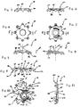
- FIG. 3 is a side elevational view of a fixation member which can be used in the apparatus of FIG. 1;
- FIG. 4 is a bottom elevational view of the fixation member of FIG. 3;
- FIG. 5 is a cross-sectional view taken along the line 5-5 of FIG. 4 as viewed in the direction of the arrows;
- FIG. 6 is a side elevational view of another fixation member which can be used in the apparatus of FIG. 1;
- FIG. 7 is a bottom elevational view of the fixation member of FIG. 6;
- FIG. 8 is a cross-sectional view taken along the line 8-8 of FIG. 7 as viewed in the direction of the arrows;
- FIG. 9 is a side elevational view of another fixation member which can be used in the apparatus of FIG. 1;
- FIG. 10 is a bottom elevational view of the fixation member of FIG. 9;
- FIG. 11 is a cross-sectional view taken along the line 11-11 of FIG. 10 as viewed in the direction of the arrows;
- FIG. 12 is a side elevational view of yet another fixation member which can be used in the apparatus of FIG. 1
- FIG. 13 is a bottom elevational view of the fixation member of FIG. 12;
- FIG. 14 is a cross-sectional view taken along the line 14-14 of FIG. 13 as viewed in the direction of the arrows;
- FIG. 15 is an enlarged view of FIG. 11;
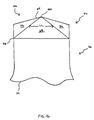
- FIG. 16 is an enlarged perspective view of a penetration structure; and
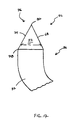
- FIG. 17 is an enlarged side elevational view of a penetration structure.
-
- While the invention is susceptible to various modifications and alternative forms, a specific embodiment thereof has been shown by way of example in the drawings and will herein be described in detail.
- Referring to FIGS. 1 and 2, there is shown an
apparatus 10 which incorporates the features of the present invention therein. As discussed in greater detail below,apparatus 10 can be utilized to immobilized bone fragments 14 of a comminuted bone 12 (hereinafter referred to as bone 12). In the exemplary embodiment ofapparatus 10 shown in FIGS. 1 and 2,apparatus 10 includes afixation member 16, afixation member 18, screws 20, and a k-wire 22. - As shown more clearly shown in FIGS. 9,10,11, and 15,
fixation member 16 includes a number ofarm members 32, astop member 46,penetration structures 42, and abody portion 24.Body portion 24 has afastener hole 52 and awire hole 66 defined therein.Body portion 24 also has anupper surface 26, alower surface 28, and aperimeter edge 30 interposed betweenupper surface 26 andlower surface 28. It should be understood that whilebody portion 24 is shown as being substantially annular shaped, other shapes are contemplated. For example,body portion 24 could be square shaped or have an oblong shape. - Still referring to FIGS. 9, 10, 11, and 15, each
arm member 32 has anend 34 secured to perimeter edge 30 ofbody portion 24 so that eacharm member 32 extends outwardly in a radial direction relative to a perpendicularcentral axis 38 ofbody portion 24. Moreover,arm members 32 are spaced apart from one another alongperimeter edge 30 such that anotch 40 is defined betweenadjacent arm members 32. It should be appreciated thatarm members 32 can have various lengths. For example, as shown in FIG. 10,arm member 32a has a length L1 which is greater than the length L2 of arm member 32b. Havingarm members 32 of various lengths is an advantage of the present invention since it enhances the ability offixation member 16 to reach and stabilize a greater surface area of comminuted bone 12 (see FIG. 1). In other words , the aforementioned advantage allowsarm members 32 offixation member 16 to reach, contact, and thus and stabilize, a greater number of bone fragments 14 (see FIGS. 1 and 2) incomminuted bone 12. - It should be understood that fixation member 16 (including arm members 32) is preferably made from a material having a relatively low elastic modulus. For example,
fixation member 16 can be made from titanium. Havingfixation member 16 made from a low elastic modulus material allowsfixation member 16 to slightly bend or flex when biased against anouter surface 44 ofbone 12 with a fastener, such as screw 20 (see FIGS. 1 and 2). In addition, it should be understood that the above describednotches 40 enhance the ability ofarm members 32 to slightly bend or flex and thus further allowfixation member 16 to readily conform to the irregular surface features ofbone 12. The above described ability to slightly flex allowsfixation member 16 to readily conform to the irregular surface features ofbone 12 and thus exert an equal pressure onouter surface 44 when biased againstbone 12 withscrew 20. Moreover, the ability offixation member 16 to slightly bend under a load ensures thatpenetration structures 42 remains in contact withbone 12 and thus substantially prevent relative movement between bone fragments 14. - As shown more clearly in FIGS. 15, 16, and 17, a
penetration structure 42 is secured to anend 36 of eacharm member 32 such that eachpenetration structure 42 extends in an axial direction relative to perpendicularcentral axis 38 ofbody portion 24. Eachpenetration structure 42 is configured so as to penetrate belowouter surface 44 ofbone 12 whenfixation member 16 is biased againstouter surface 44 ofbone 12. In addition, eachpenetration structure 42 is further configured so as to limit the aforementioned penetration such thatlower surface 28 ofbody portion 24 is prevented from contactingouter surface 44 of bone 12 (see FIGS. 1 and 2) whenfixation member 16 is biased againstouter surface 44 ofbone 12. - Each
penetration structure 42 is configured to be defined by substantially triangular shapedwall segments wall segments pyramid structure 76 having a base 78 and an apex 80.Pyramid structure 76 has a width W1 (see FIG. 16) and a thickness T1 (see FIG. 17). It should be appreciated that width W1 and thickness T1 ofpyramid structure 76 both increase moving along the direction from apex 80 tobase 78. Having the width W1 and the thickness T1 ofpyramid structure 76 increase from apex 80 tobase 78 serves two purposes. First, this configuration functions to allow eachpenetration structure 42 to penetrate belowouter surface 44 ofbone 12 to a certain degree whenfixation member 16 is biased againstouter surface 44 ofbone 12. Second, the aforementioned configuration also functions to limit the amount eachpenetration structure 42 can penetrate belowouter surface 44 ofbone 12. In particular, as apenetration structure 42 is urged againstouter surface 44 of bone 12 (for example with screw 20),apex 80 ofpyramid structure 76 is advanced throughouter surface 44 so as to create a hole (not shown) therein. Aspenetration structure 42 is further urged againstouter surface 44,penetration structure 42 becomes embedded in, or penetrates into,bone 12 such that a portion of each substantially triangular shapedwall segment pyramid structure 76 increase from apex 80 tobase 78, an increasing amount of force is required to further advancepenetration structure 42 intobone 12. This force continues to increase aspenetration structure 42 is advanced further intobone 12 until the force required to still further advancepenetration structure 42 intobone 12 approaches a point that exceeds the amount of force capable of being realistically generated by the biasing mechanism (e.g. screw 20). Once the force begins to approach the aforementioned point, the advancement ofpenetration structure 42 intobone 12 stops. It should be understood thatpenetration structures 42 are constructed so that the point where they can no longer be advanced intobone 12 occurs well beforelower surface 26 comes into contact withbone 12. Therefore, it should be appreciated that limiting the amount eachpenetration structure 42 can penetrate belowouter surface 44 ofbone 12 in the above described manner ensures thatlower surface 28 ofbody portion 24 is prevented from contactingouter surface 44 ofbone 12 whenfixation member 16 is biased againstouter surface 44 ofbone 12. - Having
penetration structures 42 configured such that they only penetrateouter surface 44 ofbone 12 to a limited degree is an important aspect of the present invention. In particular, the piercing ofpenetration structures 42 intoouter surface 44 ofbone 12 ensures thatarm members 32 offixation member 16 remain securely attached to bone fragments 14. Havingarm members 32 securely attached to bone fragments 14 ensures thatfixation member 16 functions to effectively inhibit relative movement between bone fragments 14 and thus enhances the healing ofbone 12. On the other hand, limiting the penetration ofpenetration structures 42 ensures that a space 122 (see Fig. 2) is maintained betweenouter surface 44 ofbone 12 andlower surface 28 ofbody portion 24. Havingspace 122 interposed betweenouter surface 44 andlower surface 28 ensures that an adequate blood supply is provided tobone 12. Ensuring that at an adequate blood supply is provided tobone 12 also enhances the healing ofbone 12. - In contrast to the present invention, other mechanisms utilized to inhibit the relative movement between bone fragments either do not have (i) structures configured to penetrate the bone surface, and thus do not adequately immobilize the bone fragments, or (ii) penetrating structures which are configured so as to limit their penetration of the bone surface. Mechanism which do not have penetrating structures configured to limit the penetration thereof, allow the body portion (e.g. a plate) of the mechanism to come into contact with the bone surface. As discussed above, allowing the body or plate portion to come into contact with the bone can cause the blood supply of the bone to become occluded and thus inhibit healing. Therefore, based upon the above discussion it should be appreciated that the configuration of
fixation member 16 provides significant advantages over other mechanisms utilized to immobilize bone fragments. - As shown in more detail in FIG. 15,
fastener hole 52 has anedge 58 and a center as illustrated bycenter line 56.Edge 58 includes aconvex wall portion 60 which extends towardscenter line 56.Convex wall portion 60 is configured to contact aconvex wall segment 124 defined on screw 20 (see FIG. 2) whenscrew 20 is inserted throughfastener hole 52 and utilized to securefixation member 16 tobone 12. Havingconvex wall portion 60 serve as a bearing surface forconvex wall segment 124 reduces the contact surface area betweenscrew 20 andedge 58 as compared to having a flat edge acting as a bearing surface for a flat screw wall segment. Reducing the contact surface area betweenscrew 20 andedge 58 reduces the probability that small pieces of metal or other material will be sheared off ofedge 58 orconvex wall segment 124 asscrew 20 is rotated relative to, and biased against,edge 58. - Moreover, edge 58 further includes a
land portion 62 secured to alower end 64 ofconvex wall portion 60.Land portion 62 enhances the structural strength ofbody portion 24 in the area surroundingfastener hole 52. Furthermore,fastener hole 52 is eccentrically located relative to perpendicularcentral axis 38 ofbody portion 24. Havingfaster hole 52 eccentrically located relative to perpendicularcentral axis 38 cooperates with other features offixation member 16 so as to allow a surgeon to securefixation member 16 to a relativelylarge bone fragment 14 withscrew 20 while still being able to reach smaller bone fragments 14 withpenetration structures 42. In particular, as shown in FIGS. 1 and 2, having (i) an eccentrically locatedfastener hole 52 and (ii)arm members 32 of varying lengths allowsfixation member 16 to be secured to a relativelylarge bone fragment 14 while still allowingpenetration structures 42 to reach and secure relatively small bone fragments 16. - Still referring to Fig. 15,
wire hole 66 is defined inbody portion 24 such thatwire hole 66 is spaced apart fromfastener hole 52.Wire hole 66 is configured so that wire 22 can be inserted throughwire hole 66 in a well known manner so as to stabilizefixation member 16 prior to securingfixation member 16 tobone 12 withscrew 20. - Referring now to FIGS. 9, 10, 11, and 15,
stop member 46 is connected tolower surface 28 ofbody portion 24.Stop member 46 is also configured to limit the penetration ofpenetration structures 42 so thatlower surface 28 ofbody portion 24 is prevented from contactingouter surface 44 ofbone 12 whenfixation member 16 is biased againstouter surface 44 ofbone 12. In the exemplary embodiment shown in FIGS 9, 10, 11, and 15,stop member 46 is anannular ridge 48 secured to alower edge 127 ofland portion 62 such thatannular ridge 48 extends away fromlower surface 28 ofbody portion 24. (Note securingannular ridge 48 in the above described manner results inannular ridge 48 being in a concentric relationship withfastener hole 52.) However, as discussed below, other structural configurations ofstop member 46 are contemplated. - Stop member 46 (i.e. annular ridge 48) functions to prevent
lower surface 28 ofbody portion 24 from coming into contact withouter surface 44 ofbone 12 in the following manner. Asfixation member 16 is urged againstouter surface 44 of bone 12 (for example with screw 20),lower surface 28 is advanced towardouter surface 44 until anend surface 50 ofannular ridge 48 contactsouter surface 44 ofbone 12 whereupon the advancement oflower surface 28 towardouter surface 44 is stopped. Sinceannular ridge 48 extends outwardly from lower surface 28 a certain distance,space 122 is maintained betweenlower surface 28 andouter surface 44 ofbone 12. Therefore, it should be appreciated thatstop member 46 also preventsbody portion 24 from coming into contact withouter surface 44 ofbone 12 and thus ensures that an adequate blood supply is provided tobone 12. - It should also be appreciated that
stop member 46 can be disposed on other areas offixation member 16. For example, astop member 46 can be disposed onpenetration structures 42. Additionally, astop member 46 could be disposed on eacharm member 32 if desired. For example, it is contemplated thatstop member 46 could be configured as a ridge extending fromarm members 32. In this configuration a ridge is interposed between eachpenetration structure 42 andbody portion 24 so as to limit the penetration ofpenetration structures 42. It should be further appreciated thatfixation member 16 can be equipped with both (i)penetration structures 42 and (ii)stop member 46 so these elements can cooperate to preventlower surface 28 ofbody portion 24 from coming into contact withouter surface 44 ofbone 12. On the other hand,fixation member 16 can also be equipped with justpenetration structures 42, or just stopmember 46, since either one of these elements are sufficient to preventlower surface 28 ofbody portion 24 from coming into contact withouter surface 44 ofbone 12. - Referring now to FIGS. 3-8, 12, 13, and 14 there is shown three additional embodiments of fixation members (i.e.
fixation members fixation member 16. In addition, the aforementioned fixation members function, and have the same advantages, as discussed above with regard tofixation member 16. Furthermore,fixation members fixation member 16, or be used in conjunction withfixation member 16. Therefore, only a relatively brief description of these fixation members is provided below. - Now referring to FIGS. 3, 4, and 5,
fixation member 18 includes abody portion 90 and a number ofarm members 86. In contrast tofixation member 16,fixation member 18 has a fastener hole which is concentric with a perpendicularcentral axis 104. In addition,fixation member 18 is structurally different fromfixation member 16 in thatfixation member 18 hasarm members 86 which are angled downward relative tobody portion 90 in the direction indicated by arrow 129. Furthermore,fixation member 18 does not include a stop member such asridge 48 discussed above. With respect to the aforementioned angling,arm members 86 are angled relative to perpendicularcentral axis 104 such that a linear extension of atop surface 106 ofarm members 86 defines an obtuse angle α between perpendicularcentral axis 104 and linear extension oftop surface 106. - Now referring to FIGS. 6, 7, and 8,
fixation member 92 includes abody portion 94, a number ofarm members 112, and a stop member 96 configured as anannular ridge 98. In contrast tofixation member 18,arm members 112 offixation member 92 extend radially frombody portion 94 in the direction indicated byarrow 100 such that a linear extension of atop surface 108 of eacharm member 112 defines a right angle β between the linear extension and a perpendicular central axis 102. - Referring now to FIGS. 12, 13, and 14,
fixation member 110 includes abody portion 114, a number ofarm members 120, and astop member 116 configured as an annular ridge 118.Arm members 120 offixation member 110 radially extend frombody portion 114 as previously discussed above forfixation members arm member 120 offixation member 110 has an arcuate shape. - It should be understood that the above discussed different configurations of
arm members fixation members fixation member 110 may be utilized with a relatively large screw, whilefixation members - Referring now to FIGS. 1 and 2,
apparatus 10 can be used in the following manner. Initially a surgeon placesfixation member 16 in an appropriate location onouter surface 44 ofbone 12. In particular,fixation member 16 is positioned so thatpenetration structures 42 contact several bone fragments 14. Oncefixation member 16 is positioned, an end of wire 22 is advanced throughwire hole 66 while the other end of wire 22 is inserted intobone 12. Utilizing wire 22 in the aforementioned manner stabilizesfixation member 16 untilscrew 20 is inserted throughfastener hole 52 and screwed into abone fragment 14. Screwingscrew 20 intobone fragment 14 causesfixation member 16 to be urged againstouter surface 44 ofbone 12 so thatpenetration structures 42 penetrateouter surface 44 in the previously described manner. Screwingscrew 20 intobone fragment 14 also causesstop member 46 to contactouter surface 44 ofbone 12. Thus, it should be appreciated that bothpenetration structures 42 and stopmember 46 function to ensure thatspace 122 is maintained betweenbody portion 24 andouter surface 44 ofbone 12. Therefore,fixation member 16 effectively stabilizes bone fragments 14 while ensuring that an adequate flow of blood is provided tobone 12. - As shown in FIGS. 1 and 2,
fixation member 16 can be used in conjunction with another fixation member, such asfixation member 18.Fixation member 18 is used in the same manner as described above forfixation member 16. Furthermore, wire 22 can be secured to both of thescrews 20 used to fastenfixation members fixation members - Based upon the above description it should be appreciated that the present invention provides fixation members which effectively stabilize
bone fragments 14 ofcomminuted bone 12 without substantially occluding blood flow. In addition, the fixation members of the present invention are capable of stabilizing a plurality of bone fragments 14 without using a large number ofscrews 20. In particular, the fixation members of the present invention can stabilize a plurality of bone fragments 14 (including bone fragments 14 which are to small to have ascrew 20 inserted therein) with the use of asingle screw 20.
Claims (9)
- A fixation member (16) for treating orthopaedic fractures, comprising:in which each penetration structure is defined by a first substantially triangular shaped wall segment (68), a second substantially triangular shaped wall segment (70), a third substantially triangular wall segment (72), and a fourth substantially triangular shaped wall segment (74) secured together so as to form a pyramid structure having a base (78) and an apex (80), and in which the pyramid structure has a width W1 and a thickness T1, and in which the width W1 and the thickness T1 of the pyramid structure increase from the apex to the base, so that the penetration structure is (i) configured so as to penetrate below an outer surface of a bone when the fixation member is biassed against the outer surface of the bone and (ii) further configured to limit the penetration so that the lower surface of the body portion is prevented from contacting the outer surface of the bone when the fixation member is biassed against the outer surface of the bone.a body portion (24) having (i) an upper surface (26), (ii) a lower surface (28), and (iii) a perimeter edge (30) interposed between the upper surface and the lower surface;a plurality of arm members (32) each having a first end (34) and a second end (36) , the first end of each arm member being secured to the perimeter edge such that each arm member extends in a radial direction relative to the body portion; anda plurality of penetration structures (42) secured to respective arm members at the second end thereof such that each penetration structure extends in an axial direction relative to the body portion,
- The fixation member of claim 1, in which the arm members (32) are spaced apart from one another along the perimeter edge (30) such that a notch (40) is defined between adjacent arm members.
- The fixation member of claim 1, which includes a ridge (48) secured to and extending from the lower surface (28) of the body portion (24), the ridge being configured so that an end surface (50) of the ridge contacts the outer surface of the bone when the fixation member is biassed against the outer surface (44) of the bone (12).
- The fixation member of claim 1, which includes a fastener hole (52) defined in the body portion (24).
- The fixation member of claim 4, in which the fastener hole (52) has a centre and an edge (58), and in which the said edge includes a convex wall portion (124) which extends toward the centre of the fastener hole.
- The fixation member of claim 5, in which the edge of the fastener hole (52) further includes a land portion (62) secured to a lower end (64) of the convex wall portion (124).
- The fixation member of claim 5, in which the fastener hole (52) is eccentrically located relative to a perpendicular central axis of the body portion (24).
- The fixation member of claim 5, which includes a wire hole (66) defined in the body portion (24), the wire hole being spaced apart from the fastener hole (52).
- The fixation member of claim 1, in which each of the number of arm members (32) extends in a radial direction relative to a perpendicular central axis of the body portion (24).
Applications Claiming Priority (2)
| Application Number | Priority Date | Filing Date | Title |
|---|---|---|---|
| US09/495,138 US6228087B1 (en) | 2000-01-31 | 2000-01-31 | Fixation member for treating orthopedic fractures |
| US495138 | 2000-01-31 |
Publications (3)
| Publication Number | Publication Date |
|---|---|
| EP1121904A2 EP1121904A2 (en) | 2001-08-08 |
| EP1121904A3 EP1121904A3 (en) | 2002-02-13 |
| EP1121904B1 true EP1121904B1 (en) | 2004-01-02 |
Family
ID=23967395
Family Applications (1)
| Application Number | Title | Priority Date | Filing Date |
|---|---|---|---|
| EP01300715A Expired - Lifetime EP1121904B1 (en) | 2000-01-31 | 2001-01-26 | Fixation member for treating orthopaedic fractures |
Country Status (6)
| Country | Link |
|---|---|
| US (2) | US6228087B1 (en) |
| EP (1) | EP1121904B1 (en) |
| JP (1) | JP4326708B2 (en) |
| AT (1) | ATE256995T1 (en) |
| AU (1) | AU771800B2 (en) |
| DE (1) | DE60102718T2 (en) |
Cited By (1)
| Publication number | Priority date | Publication date | Assignee | Title |
|---|---|---|---|---|
| RU2414188C1 (en) * | 2009-10-07 | 2011-03-20 | Олег Анатольевич Каплунов | Pin for osteosynthesis |
Families Citing this family (76)
| Publication number | Priority date | Publication date | Assignee | Title |
|---|---|---|---|---|
| US6228087B1 (en) * | 2000-01-31 | 2001-05-08 | Depuy Orthopaedics, Inc. | Fixation member for treating orthopedic fractures |
| DE60118255T2 (en) | 2000-07-27 | 2006-12-14 | Synthes Ag Chur | Instrument for a cranial flap clamp |
| US7993349B2 (en) * | 2000-07-27 | 2011-08-09 | Synthes Usa, Llc | Cranial flap clamp instrument |
| US7229441B2 (en) * | 2001-02-28 | 2007-06-12 | Warsaw Orthopedic, Inc. | Flexible systems for spinal stabilization and fixation |
| US6887243B2 (en) | 2001-03-30 | 2005-05-03 | Triage Medical, Inc. | Method and apparatus for bone fixation with secondary compression |
| US7344539B2 (en) * | 2001-03-30 | 2008-03-18 | Depuy Acromed, Inc. | Intervertebral connection system |
| US6511481B2 (en) * | 2001-03-30 | 2003-01-28 | Triage Medical, Inc. | Method and apparatus for fixation of proximal femoral fractures |
| US7537604B2 (en) | 2002-11-19 | 2009-05-26 | Acumed Llc | Bone plates with slots |
| US7578825B2 (en) | 2004-04-19 | 2009-08-25 | Acumed Llc | Placement of fasteners into bone |
| US7153309B2 (en) | 2002-11-19 | 2006-12-26 | Acumed Llc | Guide system for bone-repair devices |
| US20050240187A1 (en) | 2004-04-22 | 2005-10-27 | Huebner Randall J | Expanded fixation of bones |
| US8475504B2 (en) * | 2007-07-19 | 2013-07-02 | Acumed Llc | Method of bone fixation with slender spanning members disposed outside bone |
| US7717945B2 (en) | 2002-07-22 | 2010-05-18 | Acumed Llc | Orthopedic systems |
| DE10128918C2 (en) * | 2001-06-15 | 2003-06-26 | Aesculap Ag & Co Kg | Implant for fixing adjacent bone plates |
| SE524413C2 (en) * | 2002-05-23 | 2004-08-03 | Claes-Olof Stiernborg | Meringue instruments, for example for hallux surgery |
| US6793678B2 (en) | 2002-06-27 | 2004-09-21 | Depuy Acromed, Inc. | Prosthetic intervertebral motion disc having dampening |
| US6712821B2 (en) | 2002-07-12 | 2004-03-30 | Shlomo Gabbay | Sternum closure apparatus and method for helping maintain a space between parts of the sternum |
| WO2004008949A2 (en) * | 2002-07-19 | 2004-01-29 | Triage Medical, Inc. | Method and apparatus for spinal fixation |
| EP1542602B1 (en) | 2002-07-22 | 2010-11-17 | Acumed LLC | Bone fusion system |
| KR20050083916A (en) | 2002-11-19 | 2005-08-26 | 어큠드 엘엘씨 | Deformable bone plates |
| KR101081269B1 (en) | 2002-11-19 | 2011-11-08 | 어큠드 엘엘씨 | Adjustable pattern plate |
| CN100553577C (en) | 2003-06-20 | 2009-10-28 | 精密医疗责任有限公司 | System for Intraoperatively Tapping Bone Plates |
| US7070600B2 (en) * | 2003-07-16 | 2006-07-04 | Silverman Barry J | Device for treatment of orthopedic fractures |
| US7635365B2 (en) | 2003-08-28 | 2009-12-22 | Ellis Thomas J | Bone plates |
| US20050177179A1 (en) * | 2004-02-10 | 2005-08-11 | Baynham Bret O. | Surgical cable system |
| US9474560B2 (en) | 2004-04-08 | 2016-10-25 | Globus Medical, Inc | Load distribution crown |
| US7615069B2 (en) * | 2004-04-08 | 2009-11-10 | Globus Medical, Inc. | Load distribution crown |
| US7785355B2 (en) * | 2004-10-20 | 2010-08-31 | Synthes Usa, Llc | System for rib fixation |
| US7857832B2 (en) | 2004-12-08 | 2010-12-28 | Interventional Spine, Inc. | Method and apparatus for spinal stabilization |
| US7648523B2 (en) | 2004-12-08 | 2010-01-19 | Interventional Spine, Inc. | Method and apparatus for spinal stabilization |
| US8105382B2 (en) | 2006-12-07 | 2012-01-31 | Interventional Spine, Inc. | Intervertebral implant |
| US8500739B2 (en) | 2007-04-06 | 2013-08-06 | DePuy Synthes Products, LLC | Securing device to secure fixation devices to bone portions |
| US8882813B2 (en) * | 2007-10-19 | 2014-11-11 | Spinesmith Partners, L.P. | Locking mechanisms and associated methods |
| US7998176B2 (en) * | 2007-06-08 | 2011-08-16 | Interventional Spine, Inc. | Method and apparatus for spinal stabilization |
| US8900307B2 (en) | 2007-06-26 | 2014-12-02 | DePuy Synthes Products, LLC | Highly lordosed fusion cage |
| AU2009205896A1 (en) | 2008-01-17 | 2009-07-23 | Synthes Gmbh | An expandable intervertebral implant and associated method of manufacturing the same |
| BRPI0910325A8 (en) | 2008-04-05 | 2019-01-29 | Synthes Gmbh | expandable intervertebral implant |
| US9237910B2 (en) | 2012-01-26 | 2016-01-19 | Acute Innovations Llc | Clip for rib stabilization |
| US12285197B2 (en) | 2008-10-10 | 2025-04-29 | Acumed Llc | Bone fixation system with opposed mounting portions |
| US9526620B2 (en) | 2009-03-30 | 2016-12-27 | DePuy Synthes Products, Inc. | Zero profile spinal fusion cage |
| US20100331891A1 (en) * | 2009-06-24 | 2010-12-30 | Interventional Spine, Inc. | System and method for spinal fixation |
| US9393129B2 (en) | 2009-12-10 | 2016-07-19 | DePuy Synthes Products, Inc. | Bellows-like expandable interbody fusion cage |
| US8568417B2 (en) | 2009-12-18 | 2013-10-29 | Charles River Engineering Solutions And Technologies, Llc | Articulating tool and methods of using |
| US9763678B2 (en) | 2010-06-24 | 2017-09-19 | DePuy Synthes Products, Inc. | Multi-segment lateral cage adapted to flex substantially in the coronal plane |
| US8979860B2 (en) | 2010-06-24 | 2015-03-17 | DePuy Synthes Products. LLC | Enhanced cage insertion device |
| AU2011271465B2 (en) | 2010-06-29 | 2015-03-19 | Synthes Gmbh | Distractible intervertebral implant |
| US9402732B2 (en) | 2010-10-11 | 2016-08-02 | DePuy Synthes Products, Inc. | Expandable interspinous process spacer implant |
| JP6240076B2 (en) | 2011-09-30 | 2017-11-29 | アキュート・イノヴェーションズ・エルエルシー | Bone fixation system with opposing mounting parts |
| WO2014018098A1 (en) | 2012-07-26 | 2014-01-30 | DePuy Synthes Products, LLC | Expandable implant |
| US20140067069A1 (en) | 2012-08-30 | 2014-03-06 | Interventional Spine, Inc. | Artificial disc |
| US8998968B1 (en) | 2012-11-28 | 2015-04-07 | Choice Spine, Lp | Facet screw system |
| US9717601B2 (en) | 2013-02-28 | 2017-08-01 | DePuy Synthes Products, Inc. | Expandable intervertebral implant, system, kit and method |
| US9522070B2 (en) | 2013-03-07 | 2016-12-20 | Interventional Spine, Inc. | Intervertebral implant |
| US9522028B2 (en) | 2013-07-03 | 2016-12-20 | Interventional Spine, Inc. | Method and apparatus for sacroiliac joint fixation |
| WO2015167920A1 (en) | 2014-04-30 | 2015-11-05 | DePuy Synthes Products, Inc. | Tensioning instrument and related bone fixation systems |
| JP6594946B2 (en) | 2014-07-03 | 2019-10-23 | アキュームド・エルエルシー | Bone plate with movable joint |
| WO2016090500A1 (en) * | 2014-12-08 | 2016-06-16 | Noetzli Hubert Pius | Tie rod for stabilizing elements of the musculoskeletal system |
| US10285689B2 (en) * | 2015-01-07 | 2019-05-14 | Biomet C.V. | Orthopedic implant for bone fixation |
| US11426290B2 (en) | 2015-03-06 | 2022-08-30 | DePuy Synthes Products, Inc. | Expandable intervertebral implant, system, kit and method |
| US9913727B2 (en) | 2015-07-02 | 2018-03-13 | Medos International Sarl | Expandable implant |
| JP6995789B2 (en) | 2016-06-28 | 2022-01-17 | イーアイティー・エマージング・インプラント・テクノロジーズ・ゲーエムベーハー | Expandable and angle adjustable intervertebral cage |
| CN109640889B (en) | 2016-06-28 | 2021-07-30 | Eit 新兴移植技术股份有限公司 | Expandable Angle Adjustable Articulation Intervertebral Cage |
| US10537436B2 (en) | 2016-11-01 | 2020-01-21 | DePuy Synthes Products, Inc. | Curved expandable cage |
| US10888433B2 (en) | 2016-12-14 | 2021-01-12 | DePuy Synthes Products, Inc. | Intervertebral implant inserter and related methods |
| US10398563B2 (en) | 2017-05-08 | 2019-09-03 | Medos International Sarl | Expandable cage |
| US11344424B2 (en) | 2017-06-14 | 2022-05-31 | Medos International Sarl | Expandable intervertebral implant and related methods |
| US10940016B2 (en) | 2017-07-05 | 2021-03-09 | Medos International Sarl | Expandable intervertebral fusion cage |
| US11446156B2 (en) | 2018-10-25 | 2022-09-20 | Medos International Sarl | Expandable intervertebral implant, inserter instrument, and related methods |
| USD914492S1 (en) * | 2019-05-30 | 2021-03-30 | Curiteva, Inc. | Resilient fastener washer |
| US11426286B2 (en) | 2020-03-06 | 2022-08-30 | Eit Emerging Implant Technologies Gmbh | Expandable intervertebral implant |
| US11446071B2 (en) | 2020-08-03 | 2022-09-20 | Curiteva, Inc. | Resilient fastener washer |
| US11850160B2 (en) | 2021-03-26 | 2023-12-26 | Medos International Sarl | Expandable lordotic intervertebral fusion cage |
| US11752009B2 (en) | 2021-04-06 | 2023-09-12 | Medos International Sarl | Expandable intervertebral fusion cage |
| US12090064B2 (en) | 2022-03-01 | 2024-09-17 | Medos International Sarl | Stabilization members for expandable intervertebral implants, and related systems and methods |
| USD1014235S1 (en) * | 2022-03-31 | 2024-02-13 | Fluidmaster, Inc. | Washer |
| USD1015864S1 (en) * | 2022-03-31 | 2024-02-27 | Fluidmaster, Inc. | Nut |
Family Cites Families (19)
| Publication number | Priority date | Publication date | Assignee | Title |
|---|---|---|---|---|
| US173385A (en) * | 1876-02-15 | Improvement in nut-locks | ||
| US2355986A (en) | 1942-07-20 | 1944-08-15 | Mac Lean Fogg Lock Nut Co | Floor clip |
| US2511051A (en) * | 1946-06-19 | 1950-06-13 | Dzus William | Fastening device |
| GB1515293A (en) | 1974-05-29 | 1978-06-21 | Nat Res Dev | Endoprosthetic devices |
| FR2439003A1 (en) | 1978-10-20 | 1980-05-16 | Anvar | NEW OSTEOSYNTHESIS PARTS, THEIR PREPARATION AND THEIR APPLICATION |
| ZA80327B (en) | 1979-08-23 | 1981-09-30 | U Mennen | Internal fixation device for bone fractures |
| CH662936A5 (en) * | 1984-05-18 | 1987-11-13 | Technomed Gmk | BONE JOINT PLATE. |
| US4802477A (en) | 1987-05-07 | 1989-02-07 | Shlomo Gabbay | Sternum closure device |
| WO1989004150A1 (en) | 1987-11-03 | 1989-05-18 | Synthes Ag | Implant for osteosynthesis |
| US5006120A (en) | 1989-10-10 | 1991-04-09 | Carter Peter R | Distal radial fracture set and method for repairing distal radial fractures |
| JPH066810Y2 (en) | 1989-11-29 | 1994-02-23 | 旭光学工業株式会社 | Vertebral body fixation plate |
| DE4111856C1 (en) | 1991-04-11 | 1992-07-16 | Oswald Leibinger Gmbh, 7202 Muehlheim, De | |
| CH686339A5 (en) | 1991-12-10 | 1996-03-15 | Synthes Ag | Nut for the plate fixation. |
| AU5542594A (en) * | 1993-02-16 | 1994-09-14 | W.E. Michael Mikhail | Orthopaedic reconstruction plate |
| US5707373A (en) | 1996-04-26 | 1998-01-13 | Ikonos Corporation | Bone fastener and instrument for insertion thereof |
| US5718705A (en) | 1996-07-16 | 1998-02-17 | Sammarco; Giacomo J. | Internal fixation plate |
| GB2331244A (en) * | 1997-11-18 | 1999-05-19 | Univ Hull | Fracture fixation devices |
| GB9801986D0 (en) * | 1998-01-31 | 1998-03-25 | Depuy Int Ltd | A fixation device for a bone fracture |
| US6228087B1 (en) * | 2000-01-31 | 2001-05-08 | Depuy Orthopaedics, Inc. | Fixation member for treating orthopedic fractures |
-
2000
- 2000-01-31 US US09/495,138 patent/US6228087B1/en not_active Expired - Lifetime
-
2001
- 2001-01-22 AU AU16377/01A patent/AU771800B2/en not_active Ceased
- 2001-01-26 AT AT01300715T patent/ATE256995T1/en not_active IP Right Cessation
- 2001-01-26 DE DE60102718T patent/DE60102718T2/en not_active Expired - Lifetime
- 2001-01-26 EP EP01300715A patent/EP1121904B1/en not_active Expired - Lifetime
- 2001-01-30 JP JP2001022383A patent/JP4326708B2/en not_active Expired - Lifetime
- 2001-03-20 US US09/812,303 patent/US6361538B1/en not_active Expired - Lifetime
Cited By (1)
| Publication number | Priority date | Publication date | Assignee | Title |
|---|---|---|---|---|
| RU2414188C1 (en) * | 2009-10-07 | 2011-03-20 | Олег Анатольевич Каплунов | Pin for osteosynthesis |
Also Published As
| Publication number | Publication date |
|---|---|
| DE60102718T2 (en) | 2005-01-27 |
| US6228087B1 (en) | 2001-05-08 |
| US20020029042A1 (en) | 2002-03-07 |
| AU1637701A (en) | 2001-08-02 |
| DE60102718D1 (en) | 2004-05-19 |
| AU771800B2 (en) | 2004-04-01 |
| ATE256995T1 (en) | 2004-01-15 |
| EP1121904A3 (en) | 2002-02-13 |
| US6361538B1 (en) | 2002-03-26 |
| JP2001245895A (en) | 2001-09-11 |
| EP1121904A2 (en) | 2001-08-08 |
| JP4326708B2 (en) | 2009-09-09 |
Similar Documents
| Publication | Publication Date | Title |
|---|---|---|
| US6228087B1 (en) | Fixation member for treating orthopedic fractures | |
| US10973560B2 (en) | Distal radius plate | |
| US5718704A (en) | L-shape surgical buttress plate | |
| AU775910B2 (en) | Bone plate | |
| US5616144A (en) | Osteosynthesis plate system | |
| US6511482B1 (en) | Cranial bone flap fixation clip | |
| JP5101597B2 (en) | Bone stabilization system including a multi-directional threaded fixation element | |
| US9149311B2 (en) | Cervical plate fixation system | |
| US20060235397A1 (en) | Navicular fixation device | |
| US20060264946A1 (en) | Locking bone plate | |
| JPH08509396A (en) | Top clamping clamp for vertebral fixation devices | |
| EP1468655A2 (en) | Locking bone plate | |
| US8343152B2 (en) | Fixed angle dual prong pin fixation system | |
| WO2006089695A1 (en) | Plate and screws for treatment of bone fractures | |
| KR20060012325A (en) | Offset spinal cord fixation mechanism | |
| JP2006247400A (en) | Medical treatment device for humerus proximal fracture | |
| WO1999009903A1 (en) | Locking ring with bayonet for plate osteosynthesis | |
| US7938849B2 (en) | Method for treating long bone fractures | |
| KR100530931B1 (en) | Apparatus for fixing cervical | |
| AU2016200490B2 (en) | Systems and methods for using polyaxial plates | |
| AU2013202741B2 (en) | Systems and methods for using polyaxial plates | |
| ZA200204531B (en) | Bone Plate. | |
| BG63563B1 (en) | Tool for fracture repositioning |
Legal Events
| Date | Code | Title | Description |
|---|---|---|---|
| PUAI | Public reference made under article 153(3) epc to a published international application that has entered the european phase |
Free format text: ORIGINAL CODE: 0009012 |
|
| AK | Designated contracting states |
Kind code of ref document: A2 Designated state(s): AT BE CH CY DE DK ES FI FR GB GR IE IT LI LU MC NL PT SE TR |
|
| AX | Request for extension of the european patent |
Free format text: AL;LT;LV;MK;RO;SI |
|
| PUAL | Search report despatched |
Free format text: ORIGINAL CODE: 0009013 |
|
| AK | Designated contracting states |
Kind code of ref document: A3 Designated state(s): AT BE CH CY DE DK ES FI FR GB GR IE IT LI LU MC NL PT SE TR |
|
| AX | Request for extension of the european patent |
Free format text: AL;LT;LV;MK;RO;SI |
|
| RIC1 | Information provided on ipc code assigned before grant |
Free format text: 7A 61B 17/80 A, 7A 61B 17/84 B |
|
| 17P | Request for examination filed |
Effective date: 20020315 |
|
| AKX | Designation fees paid |
Free format text: AT BE CH CY DE DK ES FI FR GB GR IE IT LI LU MC NL PT SE TR |
|
| 17Q | First examination report despatched |
Effective date: 20020923 |
|
| GRAH | Despatch of communication of intention to grant a patent |
Free format text: ORIGINAL CODE: EPIDOS IGRA |
|
| GRAS | Grant fee paid |
Free format text: ORIGINAL CODE: EPIDOSNIGR3 |
|
| GRAA | (expected) grant |
Free format text: ORIGINAL CODE: 0009210 |
|
| AK | Designated contracting states |
Kind code of ref document: B1 Designated state(s): AT BE CH CY DE DK ES FI FR GB GR IE IT LI LU MC NL PT SE TR |
|
| PG25 | Lapsed in a contracting state [announced via postgrant information from national office to epo] |
Ref country code: TR Free format text: LAPSE BECAUSE OF FAILURE TO SUBMIT A TRANSLATION OF THE DESCRIPTION OR TO PAY THE FEE WITHIN THE PRESCRIBED TIME-LIMIT Effective date: 20040102 Ref country code: CY Free format text: LAPSE BECAUSE OF FAILURE TO SUBMIT A TRANSLATION OF THE DESCRIPTION OR TO PAY THE FEE WITHIN THE PRESCRIBED TIME-LIMIT Effective date: 20040102 Ref country code: BE Free format text: LAPSE BECAUSE OF FAILURE TO SUBMIT A TRANSLATION OF THE DESCRIPTION OR TO PAY THE FEE WITHIN THE PRESCRIBED TIME-LIMIT Effective date: 20040102 Ref country code: FI Free format text: LAPSE BECAUSE OF FAILURE TO SUBMIT A TRANSLATION OF THE DESCRIPTION OR TO PAY THE FEE WITHIN THE PRESCRIBED TIME-LIMIT Effective date: 20040102 Ref country code: NL Free format text: LAPSE BECAUSE OF FAILURE TO SUBMIT A TRANSLATION OF THE DESCRIPTION OR TO PAY THE FEE WITHIN THE PRESCRIBED TIME-LIMIT Effective date: 20040102 Ref country code: AT Free format text: LAPSE BECAUSE OF FAILURE TO SUBMIT A TRANSLATION OF THE DESCRIPTION OR TO PAY THE FEE WITHIN THE PRESCRIBED TIME-LIMIT Effective date: 20040102 |
|
| RIN1 | Information on inventor provided before grant (corrected) |
Inventor name: CORNWALL, G. BRYAN Inventor name: SANDERS, ROY W. Inventor name: FENAROLI, DON |
|
| REG | Reference to a national code |
Ref country code: GB Ref legal event code: FG4D |
|
| REG | Reference to a national code |
Ref country code: CH Ref legal event code: EP |
|
| PG25 | Lapsed in a contracting state [announced via postgrant information from national office to epo] |
Ref country code: LU Free format text: LAPSE BECAUSE OF NON-PAYMENT OF DUE FEES Effective date: 20040126 |
|
| REG | Reference to a national code |
Ref country code: IE Ref legal event code: FG4D |
|
| PG25 | Lapsed in a contracting state [announced via postgrant information from national office to epo] |
Ref country code: MC Free format text: LAPSE BECAUSE OF NON-PAYMENT OF DUE FEES Effective date: 20040131 |
|
| PG25 | Lapsed in a contracting state [announced via postgrant information from national office to epo] |
Ref country code: SE Free format text: LAPSE BECAUSE OF FAILURE TO SUBMIT A TRANSLATION OF THE DESCRIPTION OR TO PAY THE FEE WITHIN THE PRESCRIBED TIME-LIMIT Effective date: 20040402 Ref country code: DK Free format text: LAPSE BECAUSE OF FAILURE TO SUBMIT A TRANSLATION OF THE DESCRIPTION OR TO PAY THE FEE WITHIN THE PRESCRIBED TIME-LIMIT Effective date: 20040402 Ref country code: GR Free format text: LAPSE BECAUSE OF FAILURE TO SUBMIT A TRANSLATION OF THE DESCRIPTION OR TO PAY THE FEE WITHIN THE PRESCRIBED TIME-LIMIT Effective date: 20040402 |
|
| PG25 | Lapsed in a contracting state [announced via postgrant information from national office to epo] |
Ref country code: ES Free format text: LAPSE BECAUSE OF FAILURE TO SUBMIT A TRANSLATION OF THE DESCRIPTION OR TO PAY THE FEE WITHIN THE PRESCRIBED TIME-LIMIT Effective date: 20040413 |
|
| REF | Corresponds to: |
Ref document number: 60102718 Country of ref document: DE Date of ref document: 20040519 Kind code of ref document: P |
|
| NLV1 | Nl: lapsed or annulled due to failure to fulfill the requirements of art. 29p and 29m of the patents act | ||
| ET | Fr: translation filed | ||
| PLBE | No opposition filed within time limit |
Free format text: ORIGINAL CODE: 0009261 |
|
| STAA | Information on the status of an ep patent application or granted ep patent |
Free format text: STATUS: NO OPPOSITION FILED WITHIN TIME LIMIT |
|
| 26N | No opposition filed |
Effective date: 20041005 |
|
| REG | Reference to a national code |
Ref country code: CH Ref legal event code: PFA Owner name: DEPUY ORTHOPAEDICS, INC. Free format text: DEPUY ORTHOPAEDICS, INC.#700 ORTHOPAEDIC DRIVE#WARSAW, INDIANA 46581 (US) -TRANSFER TO- DEPUY ORTHOPAEDICS, INC.#700 ORTHOPAEDIC DRIVE#WARSAW, INDIANA 46581 (US) |
|
| PG25 | Lapsed in a contracting state [announced via postgrant information from national office to epo] |
Ref country code: PT Free format text: LAPSE BECAUSE OF NON-PAYMENT OF DUE FEES Effective date: 20040602 |
|
| REG | Reference to a national code |
Ref country code: FR Ref legal event code: PLFP Year of fee payment: 16 |
|
| PGFP | Annual fee paid to national office [announced via postgrant information from national office to epo] |
Ref country code: FR Payment date: 20151208 Year of fee payment: 16 |
|
| PGFP | Annual fee paid to national office [announced via postgrant information from national office to epo] |
Ref country code: DE Payment date: 20160119 Year of fee payment: 16 Ref country code: CH Payment date: 20160111 Year of fee payment: 16 Ref country code: IE Payment date: 20160112 Year of fee payment: 16 Ref country code: IT Payment date: 20160127 Year of fee payment: 16 |
|
| PGFP | Annual fee paid to national office [announced via postgrant information from national office to epo] |
Ref country code: GB Payment date: 20160120 Year of fee payment: 16 |
|
| REG | Reference to a national code |
Ref country code: DE Ref legal event code: R119 Ref document number: 60102718 Country of ref document: DE |
|
| REG | Reference to a national code |
Ref country code: CH Ref legal event code: PL |
|
| GBPC | Gb: european patent ceased through non-payment of renewal fee |
Effective date: 20170126 |
|
| REG | Reference to a national code |
Ref country code: FR Ref legal event code: ST Effective date: 20170929 |
|
| PG25 | Lapsed in a contracting state [announced via postgrant information from national office to epo] |
Ref country code: CH Free format text: LAPSE BECAUSE OF NON-PAYMENT OF DUE FEES Effective date: 20170131 Ref country code: LI Free format text: LAPSE BECAUSE OF NON-PAYMENT OF DUE FEES Effective date: 20170131 Ref country code: FR Free format text: LAPSE BECAUSE OF NON-PAYMENT OF DUE FEES Effective date: 20170131 |
|
| REG | Reference to a national code |
Ref country code: IE Ref legal event code: MM4A |
|
| PG25 | Lapsed in a contracting state [announced via postgrant information from national office to epo] |
Ref country code: GB Free format text: LAPSE BECAUSE OF NON-PAYMENT OF DUE FEES Effective date: 20170126 Ref country code: DE Free format text: LAPSE BECAUSE OF NON-PAYMENT OF DUE FEES Effective date: 20170801 |
|
| PG25 | Lapsed in a contracting state [announced via postgrant information from national office to epo] |
Ref country code: IT Free format text: LAPSE BECAUSE OF NON-PAYMENT OF DUE FEES Effective date: 20170126 Ref country code: IE Free format text: LAPSE BECAUSE OF NON-PAYMENT OF DUE FEES Effective date: 20170126 |