EP1121199B1 - Dispositif d'analyse chimique et/ou biochimique avec un support d'analyse - Google Patents
Dispositif d'analyse chimique et/ou biochimique avec un support d'analyse Download PDFInfo
- Publication number
- EP1121199B1 EP1121199B1 EP99947579A EP99947579A EP1121199B1 EP 1121199 B1 EP1121199 B1 EP 1121199B1 EP 99947579 A EP99947579 A EP 99947579A EP 99947579 A EP99947579 A EP 99947579A EP 1121199 B1 EP1121199 B1 EP 1121199B1
- Authority
- EP
- European Patent Office
- Prior art keywords
- support
- analysis
- thermal
- substrate
- bowl
- Prior art date
- Legal status (The legal status is an assumption and is not a legal conclusion. Google has not performed a legal analysis and makes no representation as to the accuracy of the status listed.)
- Expired - Lifetime
Links
- 238000004458 analytical method Methods 0.000 title claims abstract description 94
- 239000000126 substance Substances 0.000 title claims abstract description 10
- 239000003153 chemical reaction reagent Substances 0.000 claims abstract description 35
- 239000000758 substrate Substances 0.000 claims description 48
- 238000010438 heat treatment Methods 0.000 claims description 10
- 238000000034 method Methods 0.000 claims description 8
- 239000012530 fluid Substances 0.000 claims description 7
- 230000015572 biosynthetic process Effects 0.000 claims description 6
- 238000001816 cooling Methods 0.000 claims description 6
- 230000004888 barrier function Effects 0.000 claims description 5
- 238000004519 manufacturing process Methods 0.000 claims description 5
- 238000009413 insulation Methods 0.000 claims description 3
- 238000004026 adhesive bonding Methods 0.000 claims 2
- 239000007788 liquid Substances 0.000 description 11
- 238000005530 etching Methods 0.000 description 5
- 239000013529 heat transfer fluid Substances 0.000 description 4
- 239000011810 insulating material Substances 0.000 description 4
- XUIMIQQOPSSXEZ-UHFFFAOYSA-N Silicon Chemical compound [Si] XUIMIQQOPSSXEZ-UHFFFAOYSA-N 0.000 description 3
- 238000006243 chemical reaction Methods 0.000 description 3
- 239000002826 coolant Substances 0.000 description 3
- 238000003752 polymerase chain reaction Methods 0.000 description 3
- 229910052710 silicon Inorganic materials 0.000 description 3
- 239000010703 silicon Substances 0.000 description 3
- 230000003321 amplification Effects 0.000 description 2
- 238000012742 biochemical analysis Methods 0.000 description 2
- 238000003486 chemical etching Methods 0.000 description 2
- 239000004020 conductor Substances 0.000 description 2
- 238000009396 hybridization Methods 0.000 description 2
- 238000003199 nucleic acid amplification method Methods 0.000 description 2
- BASFCYQUMIYNBI-UHFFFAOYSA-N platinum Chemical compound [Pt] BASFCYQUMIYNBI-UHFFFAOYSA-N 0.000 description 2
- 238000007789 sealing Methods 0.000 description 2
- 238000004448 titration Methods 0.000 description 2
- LFQSCWFLJHTTHZ-UHFFFAOYSA-N Ethanol Chemical compound CCO LFQSCWFLJHTTHZ-UHFFFAOYSA-N 0.000 description 1
- 229910004298 SiO 2 Inorganic materials 0.000 description 1
- 239000003570 air Substances 0.000 description 1
- 239000012080 ambient air Substances 0.000 description 1
- 238000004925 denaturation Methods 0.000 description 1
- 230000036425 denaturation Effects 0.000 description 1
- 238000010586 diagram Methods 0.000 description 1
- 238000005553 drilling Methods 0.000 description 1
- 238000001312 dry etching Methods 0.000 description 1
- 238000001035 drying Methods 0.000 description 1
- 230000000694 effects Effects 0.000 description 1
- 238000005485 electric heating Methods 0.000 description 1
- 235000021183 entrée Nutrition 0.000 description 1
- 239000000463 material Substances 0.000 description 1
- 239000000203 mixture Substances 0.000 description 1
- 230000007935 neutral effect Effects 0.000 description 1
- 229910052697 platinum Inorganic materials 0.000 description 1
- 239000002798 polar solvent Substances 0.000 description 1
- 238000005498 polishing Methods 0.000 description 1
- 102000004169 proteins and genes Human genes 0.000 description 1
- 108090000623 proteins and genes Proteins 0.000 description 1
- 238000005086 pumping Methods 0.000 description 1
- 238000012882 sequential analysis Methods 0.000 description 1
- 239000007787 solid Substances 0.000 description 1
- 239000002904 solvent Substances 0.000 description 1
- 230000002269 spontaneous effect Effects 0.000 description 1
- 235000012431 wafers Nutrition 0.000 description 1
Images


Classifications
-
- B—PERFORMING OPERATIONS; TRANSPORTING
- B01—PHYSICAL OR CHEMICAL PROCESSES OR APPARATUS IN GENERAL
- B01L—CHEMICAL OR PHYSICAL LABORATORY APPARATUS FOR GENERAL USE
- B01L3/00—Containers or dishes for laboratory use, e.g. laboratory glassware; Droppers
- B01L3/50—Containers for the purpose of retaining a material to be analysed, e.g. test tubes
- B01L3/502—Containers for the purpose of retaining a material to be analysed, e.g. test tubes with fluid transport, e.g. in multi-compartment structures
- B01L3/5027—Containers for the purpose of retaining a material to be analysed, e.g. test tubes with fluid transport, e.g. in multi-compartment structures by integrated microfluidic structures, i.e. dimensions of channels and chambers are such that surface tension forces are important, e.g. lab-on-a-chip
-
- B—PERFORMING OPERATIONS; TRANSPORTING
- B01—PHYSICAL OR CHEMICAL PROCESSES OR APPARATUS IN GENERAL
- B01L—CHEMICAL OR PHYSICAL LABORATORY APPARATUS FOR GENERAL USE
- B01L7/00—Heating or cooling apparatus; Heat insulating devices
- B01L7/52—Heating or cooling apparatus; Heat insulating devices with provision for submitting samples to a predetermined sequence of different temperatures, e.g. for treating nucleic acid samples
- B01L7/525—Heating or cooling apparatus; Heat insulating devices with provision for submitting samples to a predetermined sequence of different temperatures, e.g. for treating nucleic acid samples with physical movement of samples between temperature zones
-
- B—PERFORMING OPERATIONS; TRANSPORTING
- B01—PHYSICAL OR CHEMICAL PROCESSES OR APPARATUS IN GENERAL
- B01L—CHEMICAL OR PHYSICAL LABORATORY APPARATUS FOR GENERAL USE
- B01L2300/00—Additional constructional details
- B01L2300/08—Geometry, shape and general structure
- B01L2300/0809—Geometry, shape and general structure rectangular shaped
- B01L2300/0816—Cards, e.g. flat sample carriers usually with flow in two horizontal directions
-
- B—PERFORMING OPERATIONS; TRANSPORTING
- B01—PHYSICAL OR CHEMICAL PROCESSES OR APPARATUS IN GENERAL
- B01L—CHEMICAL OR PHYSICAL LABORATORY APPARATUS FOR GENERAL USE
- B01L2300/00—Additional constructional details
- B01L2300/08—Geometry, shape and general structure
- B01L2300/0861—Configuration of multiple channels and/or chambers in a single devices
- B01L2300/0867—Multiple inlets and one sample wells, e.g. mixing, dilution
-
- B—PERFORMING OPERATIONS; TRANSPORTING
- B01—PHYSICAL OR CHEMICAL PROCESSES OR APPARATUS IN GENERAL
- B01L—CHEMICAL OR PHYSICAL LABORATORY APPARATUS FOR GENERAL USE
- B01L2300/00—Additional constructional details
- B01L2300/08—Geometry, shape and general structure
- B01L2300/0861—Configuration of multiple channels and/or chambers in a single devices
- B01L2300/0883—Serpentine channels
-
- B—PERFORMING OPERATIONS; TRANSPORTING
- B01—PHYSICAL OR CHEMICAL PROCESSES OR APPARATUS IN GENERAL
- B01L—CHEMICAL OR PHYSICAL LABORATORY APPARATUS FOR GENERAL USE
- B01L2300/00—Additional constructional details
- B01L2300/18—Means for temperature control
- B01L2300/1805—Conductive heating, heat from thermostatted solids is conducted to receptacles, e.g. heating plates, blocks
-
- B—PERFORMING OPERATIONS; TRANSPORTING
- B01—PHYSICAL OR CHEMICAL PROCESSES OR APPARATUS IN GENERAL
- B01L—CHEMICAL OR PHYSICAL LABORATORY APPARATUS FOR GENERAL USE
- B01L2300/00—Additional constructional details
- B01L2300/18—Means for temperature control
- B01L2300/1838—Means for temperature control using fluid heat transfer medium
-
- B—PERFORMING OPERATIONS; TRANSPORTING
- B01—PHYSICAL OR CHEMICAL PROCESSES OR APPARATUS IN GENERAL
- B01L—CHEMICAL OR PHYSICAL LABORATORY APPARATUS FOR GENERAL USE
- B01L2300/00—Additional constructional details
- B01L2300/18—Means for temperature control
- B01L2300/1883—Means for temperature control using thermal insulation
-
- B—PERFORMING OPERATIONS; TRANSPORTING
- B01—PHYSICAL OR CHEMICAL PROCESSES OR APPARATUS IN GENERAL
- B01L—CHEMICAL OR PHYSICAL LABORATORY APPARATUS FOR GENERAL USE
- B01L2400/00—Moving or stopping fluids
- B01L2400/04—Moving fluids with specific forces or mechanical means
- B01L2400/0475—Moving fluids with specific forces or mechanical means specific mechanical means and fluid pressure
- B01L2400/0487—Moving fluids with specific forces or mechanical means specific mechanical means and fluid pressure fluid pressure, pneumatics
-
- B—PERFORMING OPERATIONS; TRANSPORTING
- B01—PHYSICAL OR CHEMICAL PROCESSES OR APPARATUS IN GENERAL
- B01L—CHEMICAL OR PHYSICAL LABORATORY APPARATUS FOR GENERAL USE
- B01L3/00—Containers or dishes for laboratory use, e.g. laboratory glassware; Droppers
- B01L3/50—Containers for the purpose of retaining a material to be analysed, e.g. test tubes
- B01L3/502—Containers for the purpose of retaining a material to be analysed, e.g. test tubes with fluid transport, e.g. in multi-compartment structures
- B01L3/5027—Containers for the purpose of retaining a material to be analysed, e.g. test tubes with fluid transport, e.g. in multi-compartment structures by integrated microfluidic structures, i.e. dimensions of channels and chambers are such that surface tension forces are important, e.g. lab-on-a-chip
- B01L3/502707—Containers for the purpose of retaining a material to be analysed, e.g. test tubes with fluid transport, e.g. in multi-compartment structures by integrated microfluidic structures, i.e. dimensions of channels and chambers are such that surface tension forces are important, e.g. lab-on-a-chip characterised by the manufacture of the container or its components
Definitions
- the present invention relates to a device chemical and / or biological analysis, equipped with a analysis support which may be of the single-use type.
- the invention finds applications in fields of chemistry and biology.
- the device can be used in chemical amplification or reaction processes Polymerase Chain Reaction (PCR) polymerase for analysis of genetic material (DNA).
- PCR Polymerase Chain Reaction
- the equipment also has a cost of high manufacturing.
- the object of the invention is to propose a biological and / or chemical analysis device not having the limitations mentioned above.
- Another goal is to reduce the times of heating, cooling and allow a accurate and selective temperature control of components to be analyzed during the different phases of reaction.
- Another object of the invention is to propose a such a device can be quickly adapted to different types of products to analyze and do requiring no complex connection operations.
- the invention also aims to propose a device with an analysis support, very low cost, possibly for single use, which can be and replaced after each use, or after a limited number of uses. For example, we are considering to perform a thousand sequential analyzes with a device before throwing it away.
- the invention has more precisely for purpose a chemical analysis device and / or biological comprising an analysis support with at least one inlet bowl to collect a sample, at least one outlet bowl for delivering said sample, at least one internal channel through the bracket to connect the inlet bowl to the outlet bowl, and at least one tank to reagent, connected to each channel respectively between a inlet bowl and an outlet bowl, wherein the inlet bowl, the outlet bowl and the tank open on a first side of the support analysis.
- the device may in particular include a plurality of inlet bowls and a plurality corresponding outlet cuvettes, each cuvette inlet respectively being connected to a bowl of associated output, by means of a channel.
- micropipette micropipette
- the implementation place liquids to be analyzed in the cuvettes inlet and / or reagents in the tanks can be done by means of watertight supply of fluids such as a plug deposited on the tank or bowl and connected to a syringe or a tank under pressure.
- the supply of liquids to analyze and / or reagents can be automated at means of a dispensing robot (dispense) at high resolution.
- the sequential analyzes assuming the replacement in time of at least one reactive by another can be automated by sequential introduction into the tank corresponding of several different reagents. Enter two different reagents a neutral buffer liquid can, or not, be introduced into the tank.
- the or internal channels can be planned for extend near at least one second face of the analysis support so as to be separate from said second face only by a thin wall.
- the thin wall can present a thickness of less than 100 ⁇ m.
- the wall is chosen Thin enough to allow heat exchange with thermal sources external to the support analysis.
- the wall separating the channels of the second side can be chosen thinner than a wall separating the channels between them or basins.
- the face opposite channels to the thin wall may present a thermal barrier, this can be achieved by a layer of low thermal conductive material and / or a structuring of the substrate to locate on the channels a cavity filled with air or a little gas coolant.
- This thermal barrier makes it possible to standardize the temperature in the channels.
- the device may further comprise a thermal support independent of the analysis support, thermal support having a heat exchange face with at least a thermal source, and said thermal medium can be removably attached to the support of analysis in order to put in contact the exchange face with the second face of the analysis support.
- this support can be of the single or multiple use type uses, that is, to be thrown away after one or several uses. We mean by use the sequential realization of a number of neighboring analyzes for example 1000.
- the heat exchange face may include a or several thermostatically controlled zones, each equipped with minus a heat source.
- Thermostatic zones coincide with at least one area of the analysis support located downstream of a connection between a reagent and a channel.
- downstream used here refers to to a flow direction of the liquid to be analyzed from the entrance bowls to the bowls of exit.
- Thermal sources may include one or several electric heating resistors thermostatically controlled.
- thermal sources may also include one or several channels crossed by a heat transfer fluid. This fluid can be used to heat or cool locally the analysis support.
- the support analysis may comprise a first substrate having through openings which form respectively the bowls and reservoirs, and a second substrate, glued to the first substrate, the second substrate having grooves, covered by the first substrate to form channels, and coinciding respectively with the openings therethrough.
- This particularly simple structure allows reduce media manufacturing costs analysis.
- the first substrate can have two layers thermally weakly conductive, eg thick a few microns.
- the first substrate can present at minus a non-through opening so as to create at minus a thermal insulation cavity.
- the invention also relates to a method of implementation of an analysis device as described above, according to which the support is brought into contact with analysis with thermal support during a phase fixed-term analysis, at least one sample to be analyzed and at least one reagent being introduced into analysis support prior to the analysis phase or during the analysis phase, and then after the analysis, we remove the support analysis support thermal.
- the analysis support can be reused.
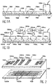
- Figure 1 is a section of a support 100 according to the invention.
- a bowl is represented 102 mainly formed by an opening crossing made in a substrate 100a of the support, near one of its ends.
- an outlet bowl 104 is made at the neighborhood of a second end.
- the bowls 102, 104 open into a first face 106 of the support 100.
- An internal channel 108 connects the inlet and outlet bowls exit.
- Channel 108 is in the form of a groove etched in a second substrate 100b glued to first substrate so that the latter covers the groove.
- the depth of the groove is practically equal to the thickness of the second substrate 100b, so that only a thin wall 110 separates the channel 108 of a second face 112 of the analysis support 100.
- the support 100 is general parallelepiped shape and the first and second faces are the opposite major faces and parallel.
- the figure also shows in section 120a, 120b, 120c reagent reservoirs arranged between inlet and outlet bowls 102 and 102.
- tanks also open on the first side 106 of the analysis support 100. Fittings or passages 122a are provided to connect each of the tanks to channel 108.
- passages 122a are shown in the plane of the figure, so that the tanks do stand out no entry and exit cuvettes in Figure 1.
- the liquid to be analyzed can be introduced into the entry bowls using a pipette.
- Reagent reservoirs can be filled in the same way.
- Figure 1B shows an analysis support according to FIG. 1A whose reservoirs 120a, 120b and 120c are respectively associated with means fluid supply 150a, 150b and 150c.
- These means comprise plugs, or supply caps 152a, 152b, 152c applied from tightly above the tanks and connected to Syringe pusher 154a, 154b and 154c which contain reagents.
- the caps can be glued to the surface of the analysis stand or tight against the surface, using a seal.
- the references 156a, 156b and 156c denote pressure sensors respectively provided on pipes connecting the syringe pumps to caps 152a, 152b and 152c, so as to control the pressure and / or flow of reagents.
- the inlet bowls and tanks are subject to the atmospheric pressure, or at a pressure set by the feeding system, while a vacuum line 124 is applied to the outlet cuvettes.
- a first spontaneous filling of the support analysis can be performed with a polar solvent (such as alcohol) followed by a nominal solvent to avoid the formation of bubbles. This filling puts benefit from a capillary effect in the channels.
- a polar solvent such as alcohol
- the analytical product arriving at the cuvettes of output can be taken there also by means of pipettes.
- Figure 2 shows more precisely and separately the two substrates 100a and 100b which form the analytical support.
- the analysis support comprises a plurality of inlet cuvettes 102 and a plurality outlet cuvettes 104.
- the bowls are shaped like openings through openings in the first substrate 100a. These openings have a flared shape in V, forming a funnel.
- each inlet bowl 102 is individually connected to an outlet basin 104 through a channel 108.
- the analysis support includes three reservoirs reagent 120a, 120b, 120c.
- each tank is common to several channels 108 to which it is connected by means of connectors 122a, 122b.
- Reference 122a designates more precisely bores of the first substrate 110a connecting a tank to branches 122b corresponding, practiced in the second substrate 110b and respectively connected to the channels. (Good heard, tanks can also be individualized for the different channels).
- Quantities of liquids (liquid to be analyzed, and reagents) that mix at the crossroads of branches 122b and channels 108 depend on the respective size of these branches and canals 108.
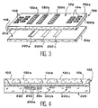
- FIG. 3 shows an analysis support 100, conforms to that of FIG. 2, the substrates of which 100a and 100b are permanently glued.
- the analysis support is represented above a corresponding thermal support 200.
- the thermal support 200 has a face heat exchange 212 facing the second side 112 of the analysis support 100, in the vicinity of which are the channels.
- the heat exchange face 212 of the thermal support 200 and the second face 112 of the analysis support are intended to be put into contact.
- the heat exchange face 212 has three thermostatic zones 220a, 220b, 220c each equipped one or more heat sources (no shown).
- the three thermostated zones 220a, 220b, 220c are arranged to coincide with portions analysis support channels located in the vicinity respectively reservoirs 120a, 120b, 120c, or more precisely branches supplying the reagents.
- the fluid in the channel 122b can pass through a only once each thermal zone or several times thanks to suitable channel patterns as shown Figure 5 described later.
- Figure 4 is a schematic section of analysis support reported on the thermal support to represent in more detail the thermostated zones.
- analysis support and thermal support are represented with a slight spacing. These supports are however in contact.
- the zones thermostats may include several sources thermal. This is the case of the thermostated zone 220a.
- the electrical resistors of the first source 230 can be brought to a temperature of 94 ° C, the heat transfer fluid of the second heat source 232 at a temperature of 55 ° C and the heat transfer fluid of the third heat source 234 at a temperature of 72 ° C.
- Thermal sources can be miniaturized so that thermal support has a submillimetric thermal resolution (less than one millimeter).
- FIG. 5 is a top view of a portion of a first substrate 100a of an analysis support and shows an alternative embodiment of a channel 108.
- Channel 108 is folded in a pattern repeated geometric.
- a thermal support can be associated with the analysis support.
- a liquid analyze can, by traversing different sections of the pattern, be brought into thermal contact so sequential with different heat sources of the thermostatically controlled area.
- Figures 6 and 7 show two variants of realization of the device making it possible to improve uniformity of temperature in the channels in insulating their upper face, i.e. the face opposite to said second face 112 of the support analysis.
- a first solution shown in Figure 6 is to perform in the upper part 100a of the hybridization support a cavity 160 (opening or not). This cavity coincides with at minus part of channel 108.
- a second solution, shown in Figure 7, is to set up between the upper and lower parts 100a, 100b of the analysis support a layer 100c of material poor conductor of heat. It is possible also to use an upper substrate equipped with a layer 100c of a thermal insulating material.
- FIGS 8 to 11, described below, give an example of a method of producing a support analysis as described above.
- a first substrate plate 100a for example made of silicon
- openings are made, as shown in FIG. 8.
- These openings constitute the bowls or tanks 102, 104, 120a, 120b, 120c.
- the chemically etched openings are made with inclined sides by anisotropic chemical etching for example (KOH) so as to give them a flared shape.
- the location of the openings is defined by an etching mask (not shown) coincident with the pattern of the grooves.
- the drilling of the layer 100c of thermal insulating material for example SiO 2 in the case of the variant proposed in FIG. 7, can be carried out, for example, by etching CHF 3 by dry process, the dimension of the perforation being defined by a mask or using the walls of the chemically created hole as a mask.
- Figure 9 shows the etching of grooves, forming the channels 108, in a second substrate 100b for example silicon.
- the engraving is done at through an etching mask (not shown) having a pattern corresponding to the desired channels. This is, for example, a chemical etching (KOH).
- KOH chemical etching
- the depth of the grooves is for example of the order of 100 ⁇ m for a substrate 100b with a thickness of 250 to 450 ⁇ m.
- a third step shown in Figure 10 includes sealing of the first and second substrates 100a and 100b, so as to communicating the cuvettes or reservoirs 102, 104, 120a, 120b, 120c, with channels (grooves) 108 correspondents. Sealing takes place, for example, by direct bonding (molecular) of the two substrates.
- the grooves 108 of the second substrate 100b are covered by the first substrate 100a to form the channels.
- a final step, shown in Figure 11, comprises thinning the second substrate 100b of way to preserve between the channel 108 and the surface 112 exterior that a thin wall 110.
- This wall 110 has a thickness of around 10 ⁇ m so as to encourage exchanges thermal.
- Thinning is achieved by etching and / or by mechanochemical polishing.
- a plurality of analysis supports conforming to the invention can be manufactured simultaneously and collectively according to the above method in two silicon wafers (corresponding to the first and second substrates).
- the process is completed by a cutting slices with the saw to individualize the analysis supports.
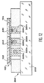
- Figure 12 shows an embodiment particular of the thermal support 200 of a device analysis according to the invention.
- the thermal support 200 comprises for essentially a base 202 on which are arranged one or several thermostatic bars.
- the thermal support includes three bars thermostatically controlled 320a, 320b, 320c which form respectively three thermostatically controlled zones.
- All or some of the bars can be drowned in a thermal insulating material.
- two bars 320b and 320c are surrounded by a solid thermal insulating material, while the first bar 320a is left in free contact with ambient air on its side faces.
- Each bar is equipped with heating and / or cooling.
- the first bar 320a is equipped with a channel 322a which traverses it and which makes it possible to thermostate it by circulation of a heat transfer fluid.
- the other bars 320b and 320c are also equipped with such channels 322b and 322c.
- the channels are respectively connected to thermostatic baths with pumping systems (not shown) for circulate the coolant.
- connection between the baths and the bars can take place by means of hydraulic connections not represented.
- the channels can be of circular type, as the figures show, but can also be equipped with fin systems to optimize the heat exchange.
- the third bar 320c is equipped an electrical resistance 330.
- the resistance electric is used here as “hot spring” while the coolant is used as “cold source”.
- the second bar 320b has an element 340 for measuring the temperature, such as a resistance, used to control, for example, the temperature of the associated thermostated bath.
- Reference 100 generally designates a removable analysis support arranged on the support thermal so as to be in contact with the bars Circulators. The detailed description of such support is not repeated here. We can refer to this subject explanations given with reference to figures preceding.
- the analysis support 100 can be simply placed on the thermal support 200. It can also be pressed against thermal support at means of a flange or a suction system not represented.
- the means for the control of temperature that is to say in particular the baths thermostats and the thermostated bars, are integral with the thermal support or in connection fluidic with the thermal support, and as the analysis support is removable, it is possible to realize the latter in a simple and inexpensive way.
Landscapes
- Chemical & Material Sciences (AREA)
- Health & Medical Sciences (AREA)
- Clinical Laboratory Science (AREA)
- Chemical Kinetics & Catalysis (AREA)
- General Health & Medical Sciences (AREA)
- Dispersion Chemistry (AREA)
- Molecular Biology (AREA)
- Biochemistry (AREA)
- Life Sciences & Earth Sciences (AREA)
- Analytical Chemistry (AREA)
- Hematology (AREA)
- Automatic Analysis And Handling Materials Therefor (AREA)
- Investigating Or Analyzing Non-Biological Materials By The Use Of Chemical Means (AREA)
- Investigating Or Analysing Biological Materials (AREA)
- Sampling And Sample Adjustment (AREA)
- Apparatus Associated With Microorganisms And Enzymes (AREA)
Description
- formation, dans un premier substrat, d'ouvertures traversantes, lesdites ouvertures correspondant respectivement à des cuvettes d'entrée ou de sortie, ou à des réservoirs de réactif,
- formation dans un deuxième substrat de rainures selon un motif permettant de relier entre elles au moins deux ouvertures du premier substrat,
- collage du premier substrat sur le deuxième substrat de façon à recouvrir les rainures,
- amincissement du deuxième substrat, après le collage, en préservant une épaisseur de substrat supérieure à une profondeur maximale des rainures.
- La figure 1A est une coupe schématique simplifiée d'un support d'analyse conforme à l'invention.
- La figure 1B montre le support d'analyse de la figure 1A équipé de moyens de remplissage de réservoirs à réactifs.
- La figure 2 est un éclaté en perspective montrant de façon plus précise la structure du support d'analyse.
- La figure 3 est une vue en perspective simplifiée d'un support d'analyse conforme à la figure 2 et d'un support thermique.
- La figure 4 est une coupe longitudinale schématique du support d'analyse mis en place sur le support thermique.
- La figure 5 est une vue en plan d'une partie d'un support d'analyse conforme à l'invention, constituant une variante par rapport aux figures 1 à 4.
- La figure 6 est une coupe transversale simplifiée d'un support d'analyse incluant une partie conforme à la figure 5.
- La figure 7 est une coupe transversale simplifiée d'un support d'analyse incluant une partie conforme à la figure 5 et constituant une variante par rapport à la figure 6.
- Les figures 8, 9, 10 et 11 sont des coupes longitudinales schématiques de substrats lors d'étapes successives de fabrication d'un support d'analyse conforme à l'invention.
- La figure 12 est une coupe transversale d'un support d'analyse et d'un support thermique conforme à l'invention et illustrant une réalisation particulière du support thermique.
Claims (16)
- Dispositif d'analyse chimique et/ou biologique comprenant :le support d'analyse (100) pouvant être rapporté de façon amovible sur le support thermique (200) afin de mettre en contact la face d'échange thermique (212) du support thermique avec la deuxième face (112) du support d'analyse (100).un support d'analyse (100) avec au moins une cuvette d'entrée (102) pour recueillir un échantillon, au moins une cuvette de sortie (104) pour délivrer ledit échantillon, au moins un canal interne (108) traversant le support pour relier la cuvette d'entrée et la cuvette de sortie, et au moins un réservoir à réactif (120a, 120b, 120c) relié à chaque canal (108) entre la cuvette d'entrée et la cuvette de sortie, dans lequel la cuvette d'entrée, la cuvette de sortie et le réservoir débouchent sur une première face (106) du support d'analyse, dans lequel le canal interne (100) s'étend à proximité d'au moins une deuxième face (112) du support d'analyse de façon à être séparé de ladite deuxième face par une paroi mince (110), etun support thermique (200) indépendant du support d'analyse (100), le support thermique présentant une face d'échange thermique (212) avec au moins une zone thermostatée (220a, 220b, 220c) équipé d'au moins une source thermique ;
- Dispositif selon la revendication 1, caractérisé en ce qu'une barrière thermique est disposée sur un côté des canaux opposé à une deuxième face du support.
- Dispositif selon la revendication 2, dans lequel la barrière thermique comporte une couche (100c) d'isolation thermique au-dessus des canaux.
- Dispositif selon la revendication 2, dans lequel la barrière thermique comporte une cavité d'isolation thermique (160) au-dessus des canaux.
- Dispositif selon la revendication 1, dans lequel la paroi mince (110) présente une épaisseur inférieure à 100 µm.
- Dispositif d'analyse selon la revendication 1, dans lequel la zone thermostatée coïncide avec au moins une zone du support d'analyse (100) située au voisinage d'un raccord (122b), entre un réservoir à réactif et un canal, lorsque le support d'analyse est reporté sur le support thermique.
- Dispositif selon la revendication 1, dans lequel le support thermique comprend des moyens de refroidissement et/ou des moyens de chauffage.
- Dispositif selon la revendication 7, dans lequel les moyens de chauffage comportent au moins une résistance électrique (230).
- Dispositif selon la revendication 7, dans lequel les moyens de refroidissement et/ou les moyens de chauffage comportent au moins un canal à fluide caloporteur.
- Dispositif selon la revendication 1, comprenant une pluralité de cuvettes d'entrée (102) et une pluralité correspondante de cuvettes de sortie (104), chaque cuvette d'entrée étant respectivement reliée à une cuvette de sortie associée au moyen d'un canal (108).
- Dispositif selon la revendication 10, comportant une pluralité de réservoirs à réactif (120a, 120b, 120c), chaque réservoir étant relié à chacun des canaux (108).
- Dispositif selon la revendication 11, avec des moyens externes (150a, 150b, 150c) de remplissage des réservoirs, comportant au moins un pousse-seringue (154a, 154b, 154c) avec ou sans mélangeur de réactifs, connecté de façon étanche à au moins un réservoir.
- Dispositif selon la revendication 12, dans lequel les moyens de remplissage comportent des capuchons d'alimentation (152a, 152b, 152c) recouvrant de façon étanche les réservoirs, et équipés chacun d'au moins une conduite reliée respectivement à au moins un pousse-seringue.
- Dispositif selon la revendication 1, dans lequel le support d'analyse (100) comprend un premier substrat (100a) présentant des ouvertures traversantes qui forment respectivement les cuvettes et réservoirs, et un deuxième substrat (100b), collé au premier substrat, le deuxième substrat présentant des rainures (108), recouvertes par le premier substrat pour former des canaux, et coïncidant avec les ouvertures traversantes.
- Procédé de fabrication d'un support d'analyse selon la revendication 1, comprenant les étapes suivantes :formation dans un premier substrat (100a), des ouvertures traversantes, lesdites ouvertures correspondant respectivement à des cuvettes d'entrée ou de sortie, ou à des réservoirs de réactif,formation dans un deuxième substrat (100b) de rainures selon un motif permettant de relier entre elles au moins deux ouvertures du premier substrat,collage du premier substrat sur le deuxième substrat de façon à recouvrir les rainures,amincissement du deuxième substrat, après le collage, en préservant une épaisseur de substrat supérieure à une profondeur maximale des rainures.
- Procédé de mise en oeuvre d'un dispositif d'analyse selon la revendication 1, selon lequel on met en contact le support d'analyse avec le support thermique pendant une phase d'analyse de durée déterminée, au moins un échantillon à analyser et au moins un réactif étant introduits dans le support d'analyse préalablement à la phase d'analyse ou pendant la phase d'analyse, puis, après la phase d'analyse, on retire le support d'analyse du support thermique.
Applications Claiming Priority (3)
| Application Number | Priority Date | Filing Date | Title |
|---|---|---|---|
| FR9813012 | 1998-10-16 | ||
| FR9813012 | 1998-10-16 | ||
| PCT/FR1999/002499 WO2000023190A1 (fr) | 1998-10-16 | 1999-10-14 | Dispositif d'analyse chimique et/ou biochimique avec un support d'analyse |
Publications (2)
| Publication Number | Publication Date |
|---|---|
| EP1121199A1 EP1121199A1 (fr) | 2001-08-08 |
| EP1121199B1 true EP1121199B1 (fr) | 2003-12-17 |
Family
ID=9531670
Family Applications (1)
| Application Number | Title | Priority Date | Filing Date |
|---|---|---|---|
| EP99947579A Expired - Lifetime EP1121199B1 (fr) | 1998-10-16 | 1999-10-14 | Dispositif d'analyse chimique et/ou biochimique avec un support d'analyse |
Country Status (6)
| Country | Link |
|---|---|
| US (1) | US6680193B1 (fr) |
| EP (1) | EP1121199B1 (fr) |
| JP (1) | JP4398096B2 (fr) |
| AT (1) | ATE256501T1 (fr) |
| DE (1) | DE69913721T2 (fr) |
| WO (1) | WO2000023190A1 (fr) |
Families Citing this family (20)
| Publication number | Priority date | Publication date | Assignee | Title |
|---|---|---|---|---|
| AU782726B2 (en) * | 1999-07-28 | 2005-08-25 | Commissariat A L'energie Atomique | Integration of biochemical protocols in a continuous flow microfluidic device |
| FR2799139B1 (fr) * | 1999-10-01 | 2002-05-03 | Genset Sa | Dispositif d'analyse biochimique comprenant un substrat microfluidique notamment pour l'amplification ou l'analyse d'acides nucleiques. |
| US6977145B2 (en) | 1999-07-28 | 2005-12-20 | Serono Genetics Institute S.A. | Method for carrying out a biochemical protocol in continuous flow in a microreactor |
| US20010048900A1 (en) * | 2000-05-24 | 2001-12-06 | Bardell Ronald L. | Jet vortex mixer |
| EP1161985B1 (fr) * | 2000-06-05 | 2005-10-26 | STMicroelectronics S.r.l. | Méthode de fabrication de microréacteurs chimiques d'un matériau semiconducteur, et microréacteur intégré |
| DE60032772T2 (de) | 2000-09-27 | 2007-11-08 | Stmicroelectronics S.R.L., Agrate Brianza | Integrierter chemischer Mikroreaktor mit thermisch isolierten Messelektroden und Verfahren zu dessen Herstellung |
| US6727479B2 (en) | 2001-04-23 | 2004-04-27 | Stmicroelectronics S.R.L. | Integrated device based upon semiconductor technology, in particular chemical microreactor |
| US20030032172A1 (en) * | 2001-07-06 | 2003-02-13 | The Regents Of The University Of California | Automated nucleic acid assay system |
| KR100442836B1 (ko) * | 2001-11-10 | 2004-08-02 | 삼성전자주식회사 | 생화학 유체를 온도가 다른 폐쇄된 챔버 구간을 따라 회전이동시키는 폐쇄 유체 회로 시스템 |
| EP1314479A3 (fr) * | 2001-11-24 | 2004-03-24 | GeSIM Gesellschaft für Silizium-Mikrosysteme mbH | Dispositif pour le transfert d' échantillons liquides |
| US20030116552A1 (en) | 2001-12-20 | 2003-06-26 | Stmicroelectronics Inc. | Heating element for microfluidic and micromechanical applications |
| US7179639B2 (en) * | 2002-03-05 | 2007-02-20 | Raveendran Pottathil | Thermal strip thermocycler |
| US20040101870A1 (en) * | 2002-11-26 | 2004-05-27 | Caubet Bruno S. | Microvolume biochemical reaction chamber |
| JP2004305009A (ja) * | 2003-04-02 | 2004-11-04 | Hitachi Ltd | 核酸増幅装置及び核酸増幅方法 |
| JP5036377B2 (ja) * | 2007-04-09 | 2012-09-26 | 株式会社日立ソリューションズ | 反応装置及び反応チップ |
| WO2009049268A1 (fr) | 2007-10-12 | 2009-04-16 | Rheonix, Inc. | Dispositif microfluidique intégré et procédés |
| FR2930457B1 (fr) * | 2008-04-24 | 2010-06-25 | Commissariat Energie Atomique | Procede de fabrication de microcanaux reconfigurables |
| US9724695B2 (en) | 2008-06-23 | 2017-08-08 | Canon U.S. Life Sciences, Inc. | Systems and methods for amplifying nucleic acids |
| AT507376B1 (de) | 2008-08-29 | 2013-09-15 | Anagnostics Bioanalysis Gmbh | Vorrichtung zum temperieren eines rotationssymetrischen behältnisses |
| CN103781543A (zh) * | 2011-08-22 | 2014-05-07 | 松下电器产业株式会社 | 微流体器件 |
Family Cites Families (10)
| Publication number | Priority date | Publication date | Assignee | Title |
|---|---|---|---|---|
| DE3926466C2 (de) * | 1989-08-10 | 1996-12-19 | Christoph Dipl Ing Caesar | Mikroreaktor zur Durchführung chemischer Reaktionen von zwei chemischen Stoffen mit starker Wärmetönung |
| BR9405989A (pt) * | 1993-03-19 | 1995-12-26 | Du Pont | Estruturas integrais para manufatura e processamento químico processo de preparação de uma estrutura integral aparelho e método de processamento químico e de manufatura |
| CN1145704C (zh) * | 1994-11-14 | 2004-04-14 | 宾夕法尼亚州大学信托人 | 中型多核苷酸扩增装置 |
| DE19519015C1 (de) * | 1995-05-24 | 1996-09-05 | Inst Physikalische Hochtech Ev | Miniaturisierter Mehrkammer-Thermocycler |
| US5589136A (en) * | 1995-06-20 | 1996-12-31 | Regents Of The University Of California | Silicon-based sleeve devices for chemical reactions |
| US6143247A (en) | 1996-12-20 | 2000-11-07 | Gamera Bioscience Inc. | Affinity binding-based system for detecting particulates in a fluid |
| US5856174A (en) * | 1995-06-29 | 1999-01-05 | Affymetrix, Inc. | Integrated nucleic acid diagnostic device |
| US5872010A (en) * | 1995-07-21 | 1999-02-16 | Northeastern University | Microscale fluid handling system |
| US5716825A (en) | 1995-11-01 | 1998-02-10 | Hewlett Packard Company | Integrated nucleic acid analysis system for MALDI-TOF MS |
| SE9700205D0 (sv) * | 1997-01-24 | 1997-01-24 | Peter Lindberg | Integrated microfluidic element |
-
1999
- 1999-10-14 WO PCT/FR1999/002499 patent/WO2000023190A1/fr not_active Ceased
- 1999-10-14 DE DE69913721T patent/DE69913721T2/de not_active Expired - Lifetime
- 1999-10-14 AT AT99947579T patent/ATE256501T1/de not_active IP Right Cessation
- 1999-10-14 US US09/806,515 patent/US6680193B1/en not_active Expired - Fee Related
- 1999-10-14 EP EP99947579A patent/EP1121199B1/fr not_active Expired - Lifetime
- 1999-10-14 JP JP2000576958A patent/JP4398096B2/ja not_active Expired - Fee Related
Also Published As
| Publication number | Publication date |
|---|---|
| US6680193B1 (en) | 2004-01-20 |
| WO2000023190A1 (fr) | 2000-04-27 |
| DE69913721T2 (de) | 2004-10-28 |
| EP1121199A1 (fr) | 2001-08-08 |
| ATE256501T1 (de) | 2004-01-15 |
| JP4398096B2 (ja) | 2010-01-13 |
| JP2002527760A (ja) | 2002-08-27 |
| DE69913721D1 (de) | 2004-01-29 |
Similar Documents
| Publication | Publication Date | Title |
|---|---|---|
| EP1121199A1 (fr) | Dispositif d'analyse chimique et/ou biochimique avec un support d'analyse | |
| US6827831B1 (en) | Controller/detector interfaces for microfluidic systems | |
| EP1400600A1 (fr) | Dispositif intégrén pour les analyses biologiques | |
| US7618811B2 (en) | Thermal cycling device | |
| US9895690B2 (en) | Microfluidic chip and application thereof | |
| US8043849B2 (en) | Thermal cycling device | |
| US20040043479A1 (en) | Multilayerd microfluidic devices for analyte reactions | |
| US20050150765A1 (en) | Integrated microchip design | |
| WO2007093939A1 (fr) | Dispositif micro-fluidique pour applications de diagnostic moleculaire | |
| US20010008613A1 (en) | Modular apparatus for chemical microanalysis | |
| CA2393690A1 (fr) | Dispositifs microfluidiques multicouches pour reactions de substances a analyser | |
| FR2795426A1 (fr) | Support d'analyse biologique a amplification | |
| US7442542B2 (en) | Shallow multi-well plastic chip for thermal multiplexing | |
| US20080236668A1 (en) | Microfluidic Valve | |
| CN101223101A (zh) | 具有集成的微型泵尤其是生化微反应器的微流体装置及其制造方法 | |
| FR2820058A1 (fr) | Procede et systeme permettant de realiser en flux continu un protocole biologique, chimique ou biochimique | |
| CN108043481B (zh) | 一种多指标检测微流控芯片及其使用方法 | |
| EP1515794A1 (fr) | DISPOSITIF FLUIDIQUE PERMETTANT DE MANIERE THERMO-PNEUMATIQUE L'ISOLEMENT ET EVENTUELLEMENT L AGITATION DU CONTENU D&apo s;UNE CAVITE OPERATOIRE | |
| FR2799139A1 (fr) | Dispositif d'analyse biochimique comprenant un substrat microfluidique notamment pour l'amplification ou l'analyse d'acides nucleiques. | |
| CN223381637U (zh) | 用于数字微流控芯片的温控部件和试剂温控装置 | |
| EP1306674A1 (fr) | Dispositif d'injection parallelisée et synchronisée pour injections séquentielles de réactifs differents | |
| US7635454B2 (en) | Integrated chemical microreactor with separated channels | |
| EP1261426B1 (fr) | Carte d'analyse et procede de sa mise en oeuvre | |
| CN218262435U (zh) | 集成逆转录反应的一体式微液滴芯片 | |
| FR2813073A1 (fr) | Dispositif de positionnement et de guidage pour la connexion etanche de capillaires a un micro-composant |
Legal Events
| Date | Code | Title | Description |
|---|---|---|---|
| PUAI | Public reference made under article 153(3) epc to a published international application that has entered the european phase |
Free format text: ORIGINAL CODE: 0009012 |
|
| 17P | Request for examination filed |
Effective date: 20010306 |
|
| AK | Designated contracting states |
Kind code of ref document: A1 Designated state(s): AT BE CH CY DE DK ES FI FR GB GR IE IT LI LU MC NL PT SE |
|
| AX | Request for extension of the european patent |
Free format text: AL;LT;LV;MK;RO;SI |
|
| 17Q | First examination report despatched |
Effective date: 20020528 |
|
| GRAP | Despatch of communication of intention to grant a patent |
Free format text: ORIGINAL CODE: EPIDOSNIGR1 |
|
| GRAS | Grant fee paid |
Free format text: ORIGINAL CODE: EPIDOSNIGR3 |
|
| GRAA | (expected) grant |
Free format text: ORIGINAL CODE: 0009210 |
|
| AK | Designated contracting states |
Kind code of ref document: B1 Designated state(s): AT BE CH CY DE DK ES FI FR GB GR IE IT LI LU MC NL PT SE |
|
| PG25 | Lapsed in a contracting state [announced via postgrant information from national office to epo] |
Ref country code: NL Free format text: LAPSE BECAUSE OF FAILURE TO SUBMIT A TRANSLATION OF THE DESCRIPTION OR TO PAY THE FEE WITHIN THE PRESCRIBED TIME-LIMIT Effective date: 20031217 Ref country code: IE Free format text: LAPSE BECAUSE OF FAILURE TO SUBMIT A TRANSLATION OF THE DESCRIPTION OR TO PAY THE FEE WITHIN THE PRESCRIBED TIME-LIMIT Effective date: 20031217 Ref country code: FI Free format text: LAPSE BECAUSE OF FAILURE TO SUBMIT A TRANSLATION OF THE DESCRIPTION OR TO PAY THE FEE WITHIN THE PRESCRIBED TIME-LIMIT Effective date: 20031217 Ref country code: CY Free format text: LAPSE BECAUSE OF FAILURE TO SUBMIT A TRANSLATION OF THE DESCRIPTION OR TO PAY THE FEE WITHIN THE PRESCRIBED TIME-LIMIT Effective date: 20031217 Ref country code: AT Free format text: LAPSE BECAUSE OF FAILURE TO SUBMIT A TRANSLATION OF THE DESCRIPTION OR TO PAY THE FEE WITHIN THE PRESCRIBED TIME-LIMIT Effective date: 20031217 |
|
| REG | Reference to a national code |
Ref country code: GB Ref legal event code: FG4D Free format text: NOT ENGLISH |
|
| REG | Reference to a national code |
Ref country code: CH Ref legal event code: EP |
|
| REG | Reference to a national code |
Ref country code: IE Ref legal event code: FG4D Free format text: FRENCH |
|
| REF | Corresponds to: |
Ref document number: 69913721 Country of ref document: DE Date of ref document: 20040129 Kind code of ref document: P |
|
| PG25 | Lapsed in a contracting state [announced via postgrant information from national office to epo] |
Ref country code: SE Free format text: LAPSE BECAUSE OF FAILURE TO SUBMIT A TRANSLATION OF THE DESCRIPTION OR TO PAY THE FEE WITHIN THE PRESCRIBED TIME-LIMIT Effective date: 20040317 Ref country code: GR Free format text: LAPSE BECAUSE OF FAILURE TO SUBMIT A TRANSLATION OF THE DESCRIPTION OR TO PAY THE FEE WITHIN THE PRESCRIBED TIME-LIMIT Effective date: 20040317 Ref country code: DK Free format text: LAPSE BECAUSE OF FAILURE TO SUBMIT A TRANSLATION OF THE DESCRIPTION OR TO PAY THE FEE WITHIN THE PRESCRIBED TIME-LIMIT Effective date: 20040317 |
|
| PG25 | Lapsed in a contracting state [announced via postgrant information from national office to epo] |
Ref country code: ES Free format text: LAPSE BECAUSE OF FAILURE TO SUBMIT A TRANSLATION OF THE DESCRIPTION OR TO PAY THE FEE WITHIN THE PRESCRIBED TIME-LIMIT Effective date: 20040328 |
|
| GBT | Gb: translation of ep patent filed (gb section 77(6)(a)/1977) |
Effective date: 20040308 |
|
| NLV1 | Nl: lapsed or annulled due to failure to fulfill the requirements of art. 29p and 29m of the patents act | ||
| REG | Reference to a national code |
Ref country code: IE Ref legal event code: FD4D |
|
| PG25 | Lapsed in a contracting state [announced via postgrant information from national office to epo] |
Ref country code: LU Free format text: LAPSE BECAUSE OF NON-PAYMENT OF DUE FEES Effective date: 20041014 |
|
| PLBE | No opposition filed within time limit |
Free format text: ORIGINAL CODE: 0009261 |
|
| STAA | Information on the status of an ep patent application or granted ep patent |
Free format text: STATUS: NO OPPOSITION FILED WITHIN TIME LIMIT |
|
| PG25 | Lapsed in a contracting state [announced via postgrant information from national office to epo] |
Ref country code: MC Free format text: LAPSE BECAUSE OF NON-PAYMENT OF DUE FEES Effective date: 20041031 Ref country code: BE Free format text: LAPSE BECAUSE OF NON-PAYMENT OF DUE FEES Effective date: 20041031 |
|
| 26N | No opposition filed |
Effective date: 20040920 |
|
| BERE | Be: lapsed |
Owner name: COMMISSARIAT A L'ENERGIE *ATOMIQUE Effective date: 20041031 |
|
| BERE | Be: lapsed |
Owner name: COMMISSARIAT A L'ENERGIE *ATOMIQUE Effective date: 20041031 |
|
| PG25 | Lapsed in a contracting state [announced via postgrant information from national office to epo] |
Ref country code: PT Free format text: LAPSE BECAUSE OF NON-PAYMENT OF DUE FEES Effective date: 20040517 |
|
| PGFP | Annual fee paid to national office [announced via postgrant information from national office to epo] |
Ref country code: FR Payment date: 20131031 Year of fee payment: 15 Ref country code: CH Payment date: 20131007 Year of fee payment: 15 Ref country code: GB Payment date: 20131010 Year of fee payment: 15 Ref country code: DE Payment date: 20131004 Year of fee payment: 15 |
|
| PGFP | Annual fee paid to national office [announced via postgrant information from national office to epo] |
Ref country code: IT Payment date: 20131011 Year of fee payment: 15 |
|
| REG | Reference to a national code |
Ref country code: DE Ref legal event code: R119 Ref document number: 69913721 Country of ref document: DE |
|
| REG | Reference to a national code |
Ref country code: CH Ref legal event code: PL |
|
| GBPC | Gb: european patent ceased through non-payment of renewal fee |
Effective date: 20141014 |
|
| PG25 | Lapsed in a contracting state [announced via postgrant information from national office to epo] |
Ref country code: CH Free format text: LAPSE BECAUSE OF NON-PAYMENT OF DUE FEES Effective date: 20141031 Ref country code: LI Free format text: LAPSE BECAUSE OF NON-PAYMENT OF DUE FEES Effective date: 20141031 Ref country code: DE Free format text: LAPSE BECAUSE OF NON-PAYMENT OF DUE FEES Effective date: 20150501 Ref country code: GB Free format text: LAPSE BECAUSE OF NON-PAYMENT OF DUE FEES Effective date: 20141014 |
|
| REG | Reference to a national code |
Ref country code: FR Ref legal event code: ST Effective date: 20150630 |
|
| PG25 | Lapsed in a contracting state [announced via postgrant information from national office to epo] |
Ref country code: FR Free format text: LAPSE BECAUSE OF NON-PAYMENT OF DUE FEES Effective date: 20141031 Ref country code: IT Free format text: LAPSE BECAUSE OF NON-PAYMENT OF DUE FEES Effective date: 20141014 |