EP1120638A1 - Spark plug with engine cylinder pressure sensor - Google Patents
Spark plug with engine cylinder pressure sensor Download PDFInfo
- Publication number
- EP1120638A1 EP1120638A1 EP00200170A EP00200170A EP1120638A1 EP 1120638 A1 EP1120638 A1 EP 1120638A1 EP 00200170 A EP00200170 A EP 00200170A EP 00200170 A EP00200170 A EP 00200170A EP 1120638 A1 EP1120638 A1 EP 1120638A1
- Authority
- EP
- European Patent Office
- Prior art keywords
- electrode
- chamber
- ignition device
- spark
- transducer
- Prior art date
- Legal status (The legal status is an assumption and is not a legal conclusion. Google has not performed a legal analysis and makes no representation as to the accuracy of the status listed.)
- Withdrawn
Links
- 230000003287 optical effect Effects 0.000 claims abstract description 32
- 238000002485 combustion reaction Methods 0.000 claims abstract description 29
- 238000004891 communication Methods 0.000 claims description 3
- 239000004020 conductor Substances 0.000 claims description 2
- 238000013022 venting Methods 0.000 claims 1
- 239000000446 fuel Substances 0.000 description 12
- 239000000203 mixture Substances 0.000 description 12
- 239000002184 metal Substances 0.000 description 9
- 229910052751 metal Inorganic materials 0.000 description 9
- 239000012212 insulator Substances 0.000 description 7
- 230000006835 compression Effects 0.000 description 4
- 238000007906 compression Methods 0.000 description 4
- 238000010304 firing Methods 0.000 description 4
- 239000000463 material Substances 0.000 description 4
- 239000000835 fiber Substances 0.000 description 3
- 238000004519 manufacturing process Methods 0.000 description 3
- 238000000034 method Methods 0.000 description 3
- 238000012360 testing method Methods 0.000 description 3
- PNEYBMLMFCGWSK-UHFFFAOYSA-N aluminium oxide Inorganic materials [O-2].[O-2].[O-2].[Al+3].[Al+3] PNEYBMLMFCGWSK-UHFFFAOYSA-N 0.000 description 2
- 238000013459 approach Methods 0.000 description 2
- 238000013461 design Methods 0.000 description 2
- 238000010892 electric spark Methods 0.000 description 2
- 239000007789 gas Substances 0.000 description 2
- 238000012986 modification Methods 0.000 description 2
- 230000004048 modification Effects 0.000 description 2
- RYGMFSIKBFXOCR-UHFFFAOYSA-N Copper Chemical compound [Cu] RYGMFSIKBFXOCR-UHFFFAOYSA-N 0.000 description 1
- 229910000831 Steel Inorganic materials 0.000 description 1
- 230000001464 adherent effect Effects 0.000 description 1
- 230000009286 beneficial effect Effects 0.000 description 1
- 239000003990 capacitor Substances 0.000 description 1
- 239000000919 ceramic Substances 0.000 description 1
- 229910010293 ceramic material Inorganic materials 0.000 description 1
- 238000005253 cladding Methods 0.000 description 1
- 239000011248 coating agent Substances 0.000 description 1
- 238000000576 coating method Methods 0.000 description 1
- 239000000567 combustion gas Substances 0.000 description 1
- 230000001010 compromised effect Effects 0.000 description 1
- 238000010276 construction Methods 0.000 description 1
- 229910052802 copper Inorganic materials 0.000 description 1
- 239000010949 copper Substances 0.000 description 1
- 229910052593 corundum Inorganic materials 0.000 description 1
- 125000004122 cyclic group Chemical group 0.000 description 1
- 230000006378 damage Effects 0.000 description 1
- 238000005553 drilling Methods 0.000 description 1
- 230000000694 effects Effects 0.000 description 1
- 238000009434 installation Methods 0.000 description 1
- 230000002452 interceptive effect Effects 0.000 description 1
- 238000012544 monitoring process Methods 0.000 description 1
- 238000010248 power generation Methods 0.000 description 1
- 230000000717 retained effect Effects 0.000 description 1
- 238000010079 rubber tapping Methods 0.000 description 1
- 230000035945 sensitivity Effects 0.000 description 1
- 239000010959 steel Substances 0.000 description 1
- 229910001845 yogo sapphire Inorganic materials 0.000 description 1
Images
Classifications
-
- G—PHYSICS
- G01—MEASURING; TESTING
- G01L—MEASURING FORCE, STRESS, TORQUE, WORK, MECHANICAL POWER, MECHANICAL EFFICIENCY, OR FLUID PRESSURE
- G01L23/00—Devices or apparatus for measuring or indicating or recording rapid changes, such as oscillations, in the pressure of steam, gas, or liquid; Indicators for determining work or energy of steam, internal-combustion, or other fluid-pressure engines from the condition of the working fluid
- G01L23/08—Devices or apparatus for measuring or indicating or recording rapid changes, such as oscillations, in the pressure of steam, gas, or liquid; Indicators for determining work or energy of steam, internal-combustion, or other fluid-pressure engines from the condition of the working fluid operated electrically
- G01L23/16—Devices or apparatus for measuring or indicating or recording rapid changes, such as oscillations, in the pressure of steam, gas, or liquid; Indicators for determining work or energy of steam, internal-combustion, or other fluid-pressure engines from the condition of the working fluid operated electrically by photoelectric means
-
- G—PHYSICS
- G01—MEASURING; TESTING
- G01L—MEASURING FORCE, STRESS, TORQUE, WORK, MECHANICAL POWER, MECHANICAL EFFICIENCY, OR FLUID PRESSURE
- G01L23/00—Devices or apparatus for measuring or indicating or recording rapid changes, such as oscillations, in the pressure of steam, gas, or liquid; Indicators for determining work or energy of steam, internal-combustion, or other fluid-pressure engines from the condition of the working fluid
- G01L23/22—Devices or apparatus for measuring or indicating or recording rapid changes, such as oscillations, in the pressure of steam, gas, or liquid; Indicators for determining work or energy of steam, internal-combustion, or other fluid-pressure engines from the condition of the working fluid for detecting or indicating knocks in internal-combustion engines; Units comprising pressure-sensitive members combined with ignitors for firing internal-combustion engines
Definitions
- the present invention generally relates to spark plugs for ignition of an air/fuel mixture within a main combustion chamber of an internal combustion engine.
- this invention relates to a spark plug configured to allow engine cylinder pressure sensing without requiring modifications to the engine and without interfering with the intended performance of the spark plug.
- Spark ignition of an air/fuel mixture within a combustion chamber of an internal combustion engine typically involves igniting the air/fuel mixture with an electric spark jumped between an electrode and a ground electrode of a spark plug.
- This type of plug conventionally used in spark ignition systems, produces a fixed flame ⁇ kernel ⁇ that relies on engine design to achieve suitable flame propagation within the combustion chamber.
- An alternative to spark ignition known in the art is torch jet-assisted spark ignition which, as taught by U.S. Patent Nos. 3,921,605 to Wyczalek, 4,924,829 to Cheng et al., 5,405,280 to Polikarpus et al., and 5,421,300 to Durling et al., offers several advantages over spark ignition approaches.
- torch jet-assisted spark ignition utilizes a jet of burning gases that are propelled into the combustion chamber in order to enhance the burning rate within the combustion chamber by providing increased turbulence as well as presenting a larger flame front area.
- a faster burning rate lower cyclic variation in cylinder pressure is achieved, which enables a higher engine efficiency with a higher compression ratio.
- spark plugs Regardless of the type of spark plug used, much can be learned of their performance and that of the engines in which they are installed by measuring engine cylinder pressure.
- pressure transducers have been separately installed in engine cylinder heads, which requires removing the head, drilling and tapping a hole for the transducer, and then reinstalling the head on the engine.
- pressure-sensing spark plugs have been developed. Plugs of this type generally have larger diameters than standard spark plugs as a result of a pressure transducer, usually of the piezocrystal-type, being mounted externally to the plug body, making their installation impossible in some engines.
- the passage required to relay cylinder pressure to the transducer is necessarily narrow and long, which promotes distortion of the pressure signal transmitted through the passage due to through-passage resonance. As a result, the pressure profile that reaches the transducer can yield inaccurate output from the transducer.
- a further disadvantage with prior art pressure-sensing spark plugs is the sensitivity of their electrical output to interference and even destruction from the high voltage spark current that is in close proximity. Misleading results from combustion tests using these plugs can also occur because the spark plug firing tip geometry must often by compromised to accommodate the transducer and its passage, causing the plug to not behave in the engine in the same way that a standard plug would.
- an improved cylinder pressure sensing device and method would be desirable.
- Such a device would preferably be less susceptible to distortion of the pressure profile reaching the transducer, insensitive to interference from the high voltage spark current, and permit the use of standard firing tip geometries.
- a pressure-sensing ignition device for use in a spark ignition system of an internal combustion engine.
- the ignition device of this invention is configured as a torch jet spark plug, and can therefore serve to ignite an air/fuel mixture within a combustion prechamber within the plug, and then propel the resulting burning gases through an orifice and into the engine main combustion chamber to increase the burning rate of the air/fuel mixture within the combustion chamber.
- the spark plug has an uncomplicated design and exhibits improved performance by employing the prechamber as a passage to a pressure transducer housed entirely within the body of the plug.
- the spark plug of this invention generally includes a body having a longitudinal axis of symmetry, first and second axial ends, and an internal chamber.
- the chamber has a first axial end and an oppositely-disposed second axial end, with its second axial end being at the second axial end of the body.
- Disposed at the second axial end of the chamber is an orifice that vents the chamber to the exterior of the body.
- An electrode and an optical pressure transducer are present within the body.
- An optical cable is connected to the optical pressure transducer for transmitting an optical pressure signal from the optical pressure transducer.
- means associated with the optical cable is provided for conducting a current to the electrode.
- the optical cable can be provided with a conductor, such as a braided flexible metal sheath, on its exterior surface, which connects to a metallic enclosure on the exterior structure of the optical pressure transducer.
- the transducer is entirely enclosed within the body of the plug, contrary to prior art pressure-sensing spark plugs that require an externally-mounted transducer.
- the electrode is an annular-shaped center electrode at the first axial end of the chamber, and the optical pressure transducer is in fluidic communication with the chamber through a passage in the center electrode, so that a separate passage dedicated solely to transmitting cylinder pressure to the transducer is unnecessary.
- the optical pressure transducer and electrode are disposed in an axial through-passage within the plug body, a portion of which also defines the chamber.
- the ignition device of this invention overcomes the disadvantages of prior art pressure-sensing spark plugs by its use of an internal chamber whose dimensions can be sufficiently generous to be relatively insusceptible to distortion of the pressure profile reaching the transducer. Because the transducer produces an optical signal, another advantage of the invention is that its operation and output are insensitive to interference from the high voltage spark current. Another advantage is that a variety of ground electrodes and firing tip geometries can be employed, including those specifically adapted for torch jet-assisted spark ignition. As a result, the present invention provides an engine cylinder pressure measuring capability to an otherwise standard-sized spark plug, such that the plug can be considered for use in many spark ignition engines.
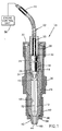
- Figure 1 shows a cross-sectional view along the longitudinal axis of a spark plug in accordance with this invention.
- a spark plug 10 adapted to be installed as a component of a spark ignition system for an internal combustion engine.
- the spark plug 10 is configured as a torch jet spark plug for use with torch jet-assisted ignition techniques, by which the plug 10 serves to increase the burning rate of an air/fuel mixture within a combustion chamber of an internal combustion engine by igniting an air/fuel mixture in a combustion prechamber 12 within an insulator body 14 of the plug 10. While those skilled in the art will recognize that the present invention is constructed to be particularly suitable for use in an automotive internal combustion engine, the teachings of the present invention are also applicable to other spark plug configurations, as well as other applications which utilize internal combustion processes for power generation.
- the insulator body 14 is preferably formed of a ceramic material, such as alumina (Al 2 O 3 ).
- the body 14 has a longitudinal passage 16, a lower portion of which defines the prechamber 12.
- an annular-shaped center electrode 18 is received, to which an electric voltage is supplied via a metal sheath 20 on the exterior of an optical cable 22.
- the optical cable 22 operates on the basis of total internal reflection resulting from the different refractive indices of the fiber core and a cladding material that surrounds the fiber core.
- the metal sheath 20 is able to conduct an electric voltage to the center electrode 18 through the metallic shell of a fiber optic pressure transducer 24.
- the transducer 24 can be of any suitable type capable of producing an optical signal based on a pressure input.
- One such transducer is commercially available from Optrand Inc. and described as a High Temperature Pressure Sensor.
- the transducer 24 and center electrode 18 are aligned within the passage 16, with a portion of the transducer 24 protruding into a central passage 26 within the center electrode 18.
- the transducer 24 and passage 26 can be threaded to secure the transducer 24 to the electrode 18.
- pressure signals are transmitted directly from the prechamber 12 to the transducer 24.
- the passage 26 is short and of comparatively large diameter, which reduces pressure wave distortion and resonance problems associated with prior art pressure-sensing plugs.
- the overall size of the plug 10 is unchanged from a conventional spark plug. Furthermore, the optical pressure signal produced by the transducer 24 is unaffected by high voltage pulses, which allows the outer sheath 20 to conduct the high voltage spark pulses for the plug 10. As a result, signal interference is avoided with this invention, even though the optical cable 22 is used to transmit both the output signal from the transducer 24 and the high voltage spark current. By combining these functions, the overall size of the plug 10 is minimized.
- the center electrode 18 and transducer 24 are retained within the passage 16 with a ceramic sleeve 28 that transfers a clamping force from a cap 30 to a collar 32 on the sleeve 28, which distributes a clamping force that maintains the center electrode 18 firmly seated on a tapered seat 34 within the passage 16.
- the cap 30 is threaded onto or otherwise secured to a metal shell 36 in which, as with spark plugs typically used with internal combustion engines, the body 14 of the plug 10 is installed and secured.
- a gasket 38 of a suitable temperature-resistant material, such as copper or soft steel, is present between the shell 36 and the insulator body 14 to create a gas-tight seal.
- External threads 40 formed at the lower end of the shell 36 are for the purpose of installing the spark plug 10 into a threaded portion of a spark plug well (not shown).
- the insulator body 14 projects through an opening 42 in the lower end of the shell 36 adjacent the threads 40.
- the center electrode 18 is shown as protruding into the upper end of the prechamber 12, opposite an orifice 44 formed at the lower end of the body 14 and prechamber 12.
- An inner electrode 46 is disposed on the internal surface 48 of the prechamber 12 adjacent the center electrode 18, and an outer hollow electrode 50 is located on the wall of the orifice 44.
- the inner electrode 46 is in the form of an annular-shaped band that forms a radial inner spark gap with the center electrode 18.
- the hollow electrode 50 is also in the form of an annular-shaped band and is interconnected with the inner electrode 46 by a conductive ⁇ stripe ⁇ 52 on the surface 48 of the prechamber 12. As such, the hollow electrode 50 acts as an extension of the inner electrode 46, and forms one electrode of an outer spark gap, which will be described below.
- the stripe 52 and the inner and hollow electrodes 46 and 50 are preferably formed by an adherent metal coating on the internal surface 48 of the prechamber 12, such as in the manner taught by U.S. Patent No. 5,421,300 to Durling et al.
- the inner and hollow electrodes 46 and 50 and the stripe 52 can be formed by a metal layer that substantially covers the entire internal surface 48 of the prechamber 12 below the center electrode 18 as taught by U.S. Patent No. 5,405,280 to Polikarpus et al., such that an electrical capacitor is effectively formed.
- Various materials and processes can be used to form the electrodes 46 and 50 and stripe 52 in accordance with the teachings of Polikarpus et al. and Durling et al., both of which are incorporated herein by reference.
- the prechamber 12 is elongate and extends along the longitudinal axis of the insulator body 14.
- the orifice 44 vents the prechamber 12 to the main combustion chamber of an engine in which the spark plug 10 is installed, and therefore allows for the intake of the air/fuel mixture during the compression stroke as well as the expulsion of combustion gases upon ignition of the air/fuel mixture within the prechamber 12, which is initiated by the center and inner electrodes 18 and 46. While shown as being generally centrally located at the end of the body 14, the orifice 44 could be radial offset.
- the volume of the prechamber 12 and the area of the orifice 44 can be selected to provide the desired characteristics for a particular engine and effect that is of interest.
- a relatively small orifice diameter restricts the exit of gasses from the prechamber 12, causing higher prechamber pressures and higher velocity jets when the plug 10 is fired, while a relatively large orifice diameter results in lower velocity jets.
- Excessively small orifices 44 restrict filling of the prechamber 12 during the engine compression stroke, especially at high engine speeds. Larger prechamber volumes produce longer duration jets, but introduce additional surface area to the combustion chamber, which is undesirable from the standpoint of heat loss and emissions.
- a ground terminal 54 is formed by an annular-shaped portion of the shell 36 surrounding the end of the insulator body 14 that protrudes from the shell 36. Together, the hollow electrode 50 and ground terminal 54 form an outer annular spark gap somewhat similar to the spark gap between the center and inner electrodes 18 and 46.
- the hollow electrode 50 of the plug 10 allows engine cylinder pressure to be transmitted to the transducer 24 without requiring any modifications to the geometry of the electrode 50 and ground terminal 54. While a particular ground electrode configuration is shown, a variety of configurations and firing tip geometries can be employed with the plug 10 of this invention, and this invention is not limited to ground electrodes that are specifically designed for torch jet-assisted spark ignition.
- an electric voltage supplied to the spark plug 10 via the metal sheath 20 will generate an electric spark at the spark gap between the center and inner electrodes 18 and 46.
- the spark then ignites an air/fuel mixture charged in the prechamber 12 from the engine ⁇ s main combustion chamber during the preceding compression stroke.
- Electric current is also then conducted along the metal stripe 52 to the hollow electrode 50, where a second spark is generated to ignite the air/fuel mixture within the main combustion chamber.
- combustion proceeds relatively simultaneously in both the prechamber 12 and the main chamber, the smaller relative volume of the prechamber 12 results in a high pressure being developed within the prechamber 12 while the pressure within the main combustion chamber is still relatively low.
- a jet which initially includes an unburned portion of the prechamber ⁇ s air/fuel mixture will be expelled from the prechamber 12, become ignited by the external flame kernel of the outer spark gap, and then travel far into the main chamber, thereby significantly increasing the combustion rate within the main chamber.
- the spark plug 10 of this invention is well suited for generating and optically transmitting cylinder pressure data to a data monitoring location outside of the plug 10.
- Figure 1 schematically shows an engine control unit 56 that can be coupled to the optical cable 22 and its metal sheath 20 to enable pressure-based engine control of a test or production engine.
- the plug 10 of this invention is not limited to experimental uses, but can be incorporated into a production engine control system.
Landscapes
- Chemical & Material Sciences (AREA)
- Engineering & Computer Science (AREA)
- Combustion & Propulsion (AREA)
- Physics & Mathematics (AREA)
- General Physics & Mathematics (AREA)
- Ignition Installations For Internal Combustion Engines (AREA)
- Spark Plugs (AREA)
Abstract
Description
- The present invention generally relates to spark plugs for ignition of an air/fuel mixture within a main combustion chamber of an internal combustion engine. In particular, this invention relates to a spark plug configured to allow engine cylinder pressure sensing without requiring modifications to the engine and without interfering with the intended performance of the spark plug.
- Spark ignition of an air/fuel mixture within a combustion chamber of an internal combustion engine typically involves igniting the air/fuel mixture with an electric spark jumped between an electrode and a ground electrode of a spark plug. This type of plug, conventionally used in spark ignition systems, produces a fixed flame □kernel□ that relies on engine design to achieve suitable flame propagation within the combustion chamber. An alternative to spark ignition known in the art is torch jet-assisted spark ignition which, as taught by U.S. Patent Nos. 3,921,605 to Wyczalek, 4,924,829 to Cheng et al., 5,405,280 to Polikarpus et al., and 5,421,300 to Durling et al., offers several advantages over spark ignition approaches. As the name suggests, torch jet-assisted spark ignition utilizes a jet of burning gases that are propelled into the combustion chamber in order to enhance the burning rate within the combustion chamber by providing increased turbulence as well as presenting a larger flame front area. As a result of a faster burning rate, lower cyclic variation in cylinder pressure is achieved, which enables a higher engine efficiency with a higher compression ratio.
- Regardless of the type of spark plug used, much can be learned of their performance and that of the engines in which they are installed by measuring engine cylinder pressure. In the past, pressure transducers have been separately installed in engine cylinder heads, which requires removing the head, drilling and tapping a hole for the transducer, and then reinstalling the head on the engine. In view of the labor required with this approach, pressure-sensing spark plugs have been developed. Plugs of this type generally have larger diameters than standard spark plugs as a result of a pressure transducer, usually of the piezocrystal-type, being mounted externally to the plug body, making their installation impossible in some engines. The passage required to relay cylinder pressure to the transducer is necessarily narrow and long, which promotes distortion of the pressure signal transmitted through the passage due to through-passage resonance. As a result, the pressure profile that reaches the transducer can yield inaccurate output from the transducer.
- A further disadvantage with prior art pressure-sensing spark plugs is the sensitivity of their electrical output to interference and even destruction from the high voltage spark current that is in close proximity. Misleading results from combustion tests using these plugs can also occur because the spark plug firing tip geometry must often by compromised to accommodate the transducer and its passage, causing the plug to not behave in the engine in the same way that a standard plug would.
- From the above, it can be appreciated that an improved cylinder pressure sensing device and method would be desirable. Such a device would preferably be less susceptible to distortion of the pressure profile reaching the transducer, insensitive to interference from the high voltage spark current, and permit the use of standard firing tip geometries.
- According to the present invention, there is provided a pressure-sensing ignition device for use in a spark ignition system of an internal combustion engine. The ignition device of this invention is configured as a torch jet spark plug, and can therefore serve to ignite an air/fuel mixture within a combustion prechamber within the plug, and then propel the resulting burning gases through an orifice and into the engine main combustion chamber to increase the burning rate of the air/fuel mixture within the combustion chamber. The spark plug has an uncomplicated design and exhibits improved performance by employing the prechamber as a passage to a pressure transducer housed entirely within the body of the plug.
- The spark plug of this invention generally includes a body having a longitudinal axis of symmetry, first and second axial ends, and an internal chamber. The chamber has a first axial end and an oppositely-disposed second axial end, with its second axial end being at the second axial end of the body. Disposed at the second axial end of the chamber is an orifice that vents the chamber to the exterior of the body. An electrode and an optical pressure transducer are present within the body. An optical cable is connected to the optical pressure transducer for transmitting an optical pressure signal from the optical pressure transducer. Finally, means associated with the optical cable is provided for conducting a current to the electrode. For example, the optical cable can be provided with a conductor, such as a braided flexible metal sheath, on its exterior surface, which connects to a metallic enclosure on the exterior structure of the optical pressure transducer.
- Based on the above construction, the transducer is entirely enclosed within the body of the plug, contrary to prior art pressure-sensing spark plugs that require an externally-mounted transducer. Preferably, the electrode is an annular-shaped center electrode at the first axial end of the chamber, and the optical pressure transducer is in fluidic communication with the chamber through a passage in the center electrode, so that a separate passage dedicated solely to transmitting cylinder pressure to the transducer is unnecessary. Another preferred aspect of the invention is that the optical pressure transducer and electrode are disposed in an axial through-passage within the plug body, a portion of which also defines the chamber.
- The ignition device of this invention overcomes the disadvantages of prior art pressure-sensing spark plugs by its use of an internal chamber whose dimensions can be sufficiently generous to be relatively insusceptible to distortion of the pressure profile reaching the transducer. Because the transducer produces an optical signal, another advantage of the invention is that its operation and output are insensitive to interference from the high voltage spark current. Another advantage is that a variety of ground electrodes and firing tip geometries can be employed, including those specifically adapted for torch jet-assisted spark ignition. As a result, the present invention provides an engine cylinder pressure measuring capability to an otherwise standard-sized spark plug, such that the plug can be considered for use in many spark ignition engines. These advantages are not only beneficial to laboratory testing, but also can be employed for pressure-based engine control of a production engine.
- Other objects and advantages of this invention will be better appreciated from the following detailed description.
- The present invention will now be described, by way of example, with reference to the accompanying drawings, in which Figure 1 shows a cross-sectional view along the longitudinal axis of a spark plug in accordance with this invention.
- Shown in Figure 1 is a
spark plug 10 adapted to be installed as a component of a spark ignition system for an internal combustion engine. As depicted, thespark plug 10 is configured as a torch jet spark plug for use with torch jet-assisted ignition techniques, by which theplug 10 serves to increase the burning rate of an air/fuel mixture within a combustion chamber of an internal combustion engine by igniting an air/fuel mixture in a combustion prechamber 12 within aninsulator body 14 of theplug 10. While those skilled in the art will recognize that the present invention is constructed to be particularly suitable for use in an automotive internal combustion engine, the teachings of the present invention are also applicable to other spark plug configurations, as well as other applications which utilize internal combustion processes for power generation. - As with spark plugs typically used with internal combustion engines, the
insulator body 14 is preferably formed of a ceramic material, such as alumina (Al2O3). Thebody 14 has alongitudinal passage 16, a lower portion of which defines theprechamber 12. In an upper portion of thepassage 16, an annular-shaped center electrode 18 is received, to which an electric voltage is supplied via ametal sheath 20 on the exterior of anoptical cable 22. As known in the art, theoptical cable 22 operates on the basis of total internal reflection resulting from the different refractive indices of the fiber core and a cladding material that surrounds the fiber core. As seen in Figure 1, themetal sheath 20 is able to conduct an electric voltage to thecenter electrode 18 through the metallic shell of a fiberoptic pressure transducer 24. Thetransducer 24 can be of any suitable type capable of producing an optical signal based on a pressure input. One such transducer is commercially available from Optrand Inc. and described as a High Temperature Pressure Sensor. - As shown, the
transducer 24 andcenter electrode 18 are aligned within thepassage 16, with a portion of thetransducer 24 protruding into acentral passage 26 within thecenter electrode 18. Thetransducer 24 andpassage 26 can be threaded to secure thetransducer 24 to theelectrode 18. Through thepassage 26, pressure signals are transmitted directly from theprechamber 12 to thetransducer 24. Thepassage 26 is short and of comparatively large diameter, which reduces pressure wave distortion and resonance problems associated with prior art pressure-sensing plugs. - With the
transducer 24 axially located with thecenter electrode 18 within theinsulator body 14, the overall size of theplug 10 is unchanged from a conventional spark plug. Furthermore, the optical pressure signal produced by thetransducer 24 is unaffected by high voltage pulses, which allows theouter sheath 20 to conduct the high voltage spark pulses for theplug 10. As a result, signal interference is avoided with this invention, even though theoptical cable 22 is used to transmit both the output signal from thetransducer 24 and the high voltage spark current. By combining these functions, the overall size of theplug 10 is minimized. - As shown, the
center electrode 18 andtransducer 24 are retained within thepassage 16 with aceramic sleeve 28 that transfers a clamping force from acap 30 to acollar 32 on thesleeve 28, which distributes a clamping force that maintains thecenter electrode 18 firmly seated on atapered seat 34 within thepassage 16. Thecap 30 is threaded onto or otherwise secured to ametal shell 36 in which, as with spark plugs typically used with internal combustion engines, thebody 14 of theplug 10 is installed and secured. Agasket 38 of a suitable temperature-resistant material, such as copper or soft steel, is present between theshell 36 and theinsulator body 14 to create a gas-tight seal.External threads 40 formed at the lower end of theshell 36 are for the purpose of installing thespark plug 10 into a threaded portion of a spark plug well (not shown). Theinsulator body 14 projects through anopening 42 in the lower end of theshell 36 adjacent thethreads 40. - The
center electrode 18 is shown as protruding into the upper end of theprechamber 12, opposite anorifice 44 formed at the lower end of thebody 14 andprechamber 12. Aninner electrode 46 is disposed on theinternal surface 48 of theprechamber 12 adjacent thecenter electrode 18, and an outerhollow electrode 50 is located on the wall of theorifice 44. Theinner electrode 46 is in the form of an annular-shaped band that forms a radial inner spark gap with thecenter electrode 18. Thehollow electrode 50 is also in the form of an annular-shaped band and is interconnected with theinner electrode 46 by a conductive □stripe□ 52 on thesurface 48 of theprechamber 12. As such, thehollow electrode 50 acts as an extension of theinner electrode 46, and forms one electrode of an outer spark gap, which will be described below. The stripe 52 and the inner andhollow electrodes internal surface 48 of theprechamber 12, such as in the manner taught by U.S. Patent No. 5,421,300 to Durling et al. The inner andhollow electrodes internal surface 48 of theprechamber 12 below thecenter electrode 18 as taught by U.S. Patent No. 5,405,280 to Polikarpus et al., such that an electrical capacitor is effectively formed. Various materials and processes can be used to form theelectrodes - As shown in Figure 1, the
prechamber 12 is elongate and extends along the longitudinal axis of theinsulator body 14. Theorifice 44 vents theprechamber 12 to the main combustion chamber of an engine in which thespark plug 10 is installed, and therefore allows for the intake of the air/fuel mixture during the compression stroke as well as the expulsion of combustion gases upon ignition of the air/fuel mixture within theprechamber 12, which is initiated by the center andinner electrodes body 14, theorifice 44 could be radial offset. The volume of theprechamber 12 and the area of theorifice 44 can be selected to provide the desired characteristics for a particular engine and effect that is of interest. For a given prechamber volume, a relatively small orifice diameter restricts the exit of gasses from theprechamber 12, causing higher prechamber pressures and higher velocity jets when theplug 10 is fired, while a relatively large orifice diameter results in lower velocity jets. Excessivelysmall orifices 44 restrict filling of theprechamber 12 during the engine compression stroke, especially at high engine speeds. Larger prechamber volumes produce longer duration jets, but introduce additional surface area to the combustion chamber, which is undesirable from the standpoint of heat loss and emissions. - From the above, it can be seen that there is no single preferred orifice diameter and prechamber volume combination for all engines, and persons skilled in the art will recognize that there are potential advantages of various combinations. For illustrative purposes, one such combination which has been found to perform suitably involves the use of a
prechamber 12 whose volume is on the order of about 0.2 to about 0.4 cubic centimeters, in combination with acentral orifice 44 having a cross-sectional area of about 1.7 to about 3.8 square millimeters. - In the embodiment shown in Figure 1, a
ground terminal 54 is formed by an annular-shaped portion of theshell 36 surrounding the end of theinsulator body 14 that protrudes from theshell 36. Together, thehollow electrode 50 andground terminal 54 form an outer annular spark gap somewhat similar to the spark gap between the center andinner electrodes hollow electrode 50 of theplug 10 allows engine cylinder pressure to be transmitted to thetransducer 24 without requiring any modifications to the geometry of theelectrode 50 andground terminal 54. While a particular ground electrode configuration is shown, a variety of configurations and firing tip geometries can be employed with theplug 10 of this invention, and this invention is not limited to ground electrodes that are specifically designed for torch jet-assisted spark ignition. - With the embodiment shown in Figure 1, it can be seen that an electric voltage supplied to the
spark plug 10 via themetal sheath 20 will generate an electric spark at the spark gap between the center andinner electrodes prechamber 12 from the engine□s main combustion chamber during the preceding compression stroke. Electric current is also then conducted along the metal stripe 52 to thehollow electrode 50, where a second spark is generated to ignite the air/fuel mixture within the main combustion chamber. Though combustion proceeds relatively simultaneously in both theprechamber 12 and the main chamber, the smaller relative volume of theprechamber 12 results in a high pressure being developed within theprechamber 12 while the pressure within the main combustion chamber is still relatively low. As a result, a jet which initially includes an unburned portion of the prechamber□s air/fuel mixture will be expelled from theprechamber 12, become ignited by the external flame kernel of the outer spark gap, and then travel far into the main chamber, thereby significantly increasing the combustion rate within the main chamber. - The
spark plug 10 of this invention is well suited for generating and optically transmitting cylinder pressure data to a data monitoring location outside of theplug 10. Alternatively, Figure 1 schematically shows anengine control unit 56 that can be coupled to theoptical cable 22 and itsmetal sheath 20 to enable pressure-based engine control of a test or production engine. Accordingly, in contrast with prior art pressure-sensing spark plugs, theplug 10 of this invention is not limited to experimental uses, but can be incorporated into a production engine control system. - While the invention has been described in terms of a preferred embodiment, it is apparent that other forms could be adopted by one skilled in the art. For example, appropriate materials could be substituted, and the teachings of this invention could be employed in different environments. Furthermore, though shown as being configured for a torch-jet assisted spark ignition system, the
plug 10 is not required to be configured or operate to generate a torch jet. Accordingly, the scope of the invention is to be limited only by the following claims.
Claims (11)
- An ignition device (10) having a body (14) with an exterior, a longitudinal axis of symmetry, first and second axial ends, an electrode (18) in the body (14), a chamber (12) within the body (14), the chamber (12) having an orifice (44) at the second axial end of the body (14) for venting the chamber (12) to the exterior of the body (14), characterized in that the device (10) comprises:an optical pressure transducer (24) in the body (14);an optical cable (22) connected to the optical pressure transducer (24) for transmitting an optical pressure signal from the optical pressure transducer (24); andmeans (20) for conducting a current to the electrode (18).
- An ignition device (10) according to claim 1, wherein the electrode (18) is an annular-shaped center electrode (18) at an axial end of the chamber (12) opposite the orifice (44), the center electrode (18) having an axial passage (26) therethrough.
- An ignition device (10) according to claim 2, wherein the optical pressure transducer (24) is in fluidic communication with the chamber (12) through the axial passage (26) in the center electrode (18).
- An ignition device (10) according to claim 1, wherein the body (14) further comprises an axial passage (16) therethrough.
- An ignition device (10) according to claim 4, wherein the optical pressure transducer (24) and the electrode (18) are disposed in the axial passage (16) and the chamber (12) is defined by a portion of the axial passage (16).
- An ignition device (10) according to claim 5, wherein the electrode (18) is an annular-shaped center electrode (18) at an axial end of the chamber (12) opposite the orifice (44), the center electrode (18) having an axial passage (26) therethrough.
- An ignition device (10) according to claim 6, wherein the optical pressure transducer (24) is in fluidic communication with the chamber (12) through the axial passage (26) in the center electrode (18).
- An ignition device (10) according to claim 1, wherein the conducting means (20) is a conductor (20) on at least a portion of an exterior surface of the optical cable (22).
- An ignition device (10) according to claim 1, wherein the electrode (18) is an annular-shaped center electrode (18) at a first axial end of the chamber (12) opposite the orifice (44), the ignition device (10) further comprising;an annular-shaped second electrode (46) at the first axial end of the chamber (12) and surrounding the electrode (18) to form an annular-shaped gap therewith;an annular-shaped third electrode (50) within the orifice (44); andmeans 52) within the chamber (12) for electrically interconnecting the second and third electrodes (46,50).
- An ignition device (10) according to claim 9, further comprising a ground electrode (54) adjacent the third electrode (50) and forming a gap therewith.
- An ignition device (10) according to claim 1, further comprising means (56) for controlling operation of an internal combustion engine using the optical pressure signal from the optical pressure transducer (24).
Applications Claiming Priority (2)
| Application Number | Priority Date | Filing Date | Title |
|---|---|---|---|
| US09/243,093 US6359377B1 (en) | 1999-02-02 | 1999-02-02 | Spark plug with engine cylinder pressure sensor |
| US243093 | 2002-09-13 |
Publications (1)
| Publication Number | Publication Date |
|---|---|
| EP1120638A1 true EP1120638A1 (en) | 2001-08-01 |
Family
ID=22917337
Family Applications (1)
| Application Number | Title | Priority Date | Filing Date |
|---|---|---|---|
| EP00200170A Withdrawn EP1120638A1 (en) | 1999-02-02 | 2000-01-18 | Spark plug with engine cylinder pressure sensor |
Country Status (2)
| Country | Link |
|---|---|
| US (1) | US6359377B1 (en) |
| EP (1) | EP1120638A1 (en) |
Cited By (2)
| Publication number | Priority date | Publication date | Assignee | Title |
|---|---|---|---|---|
| WO2007070908A1 (en) | 2005-12-22 | 2007-06-28 | Avl List Gmbh | Apparatus for measuring the cylinder internal pressure of internal combustion engines |
| WO2007068015A3 (en) * | 2005-12-13 | 2007-10-11 | Avl List Gmbh | Device for the measurement of the internal cylinder pressure of internal combustion engines |
Families Citing this family (9)
| Publication number | Priority date | Publication date | Assignee | Title |
|---|---|---|---|---|
| US7021275B2 (en) * | 2000-09-07 | 2006-04-04 | Savage Enterprises, Inc. | Igniter for internal combustion engines operating over a wide range of air fuel ratios |
| US6611083B2 (en) * | 2000-12-15 | 2003-08-26 | Savage Enterprises, Inc. | Torch jet spark plug electrode |
| US7022968B1 (en) * | 2003-10-21 | 2006-04-04 | National Semiconductor Corporation | Optical sensor that measures the light output by the combustion chamber of an internal combustion engine |
| US7131423B2 (en) * | 2004-10-06 | 2006-11-07 | Point-Man Aeronautics, L.L.C. | Fuel injection spark ignition system |
| DE102005060139B4 (en) * | 2005-12-16 | 2010-02-04 | Giese, Erhard, Dr. | spark plug |
| US20090025669A1 (en) * | 2007-07-25 | 2009-01-29 | Gerald Filipek | Heat source supplied glow plug/plasma torch and optional spark plasma torch for accomplishing more efficient piston combustion |
| US8069836B2 (en) * | 2009-03-11 | 2011-12-06 | Point-Man Aeronautics, Llc | Fuel injection stream parallel opposed multiple electrode spark gap for fuel injector |
| US10472072B2 (en) * | 2015-11-25 | 2019-11-12 | Hamilton Sundstrand Corporation | Supply tube for sensor |
| USD1107492S1 (en) * | 2024-03-08 | 2025-12-30 | Kaz Europe Sárl | Drinking vessel |
Citations (2)
| Publication number | Priority date | Publication date | Assignee | Title |
|---|---|---|---|---|
| US4393687A (en) * | 1980-01-18 | 1983-07-19 | Robert Bosch Gmbh | Sensor arrangement |
| WO1997031251A1 (en) * | 1995-02-21 | 1997-08-28 | Optrand, Inc. | Fiber optic combustion pressure sensors for engine knock and misfire detection |
Family Cites Families (4)
| Publication number | Priority date | Publication date | Assignee | Title |
|---|---|---|---|---|
| US5014656A (en) | 1990-04-25 | 1991-05-14 | General Motors Corporation | Internal combustion engine having a permanent ground electrode and replaceable center electrode element |
| US5405280A (en) | 1994-02-28 | 1995-04-11 | General Motors Corporation | Integrated molding and inking process for forming a torch jet spark plug |
| US5421300A (en) | 1994-02-28 | 1995-06-06 | General Motors Corporation | Torch jet spark plug |
| US6204594B1 (en) * | 1998-06-12 | 2001-03-20 | Cooper Automotive Products, Inc. | Spark plug with pressure sensor |
-
1999
- 1999-02-02 US US09/243,093 patent/US6359377B1/en not_active Expired - Fee Related
-
2000
- 2000-01-18 EP EP00200170A patent/EP1120638A1/en not_active Withdrawn
Patent Citations (2)
| Publication number | Priority date | Publication date | Assignee | Title |
|---|---|---|---|---|
| US4393687A (en) * | 1980-01-18 | 1983-07-19 | Robert Bosch Gmbh | Sensor arrangement |
| WO1997031251A1 (en) * | 1995-02-21 | 1997-08-28 | Optrand, Inc. | Fiber optic combustion pressure sensors for engine knock and misfire detection |
Cited By (2)
| Publication number | Priority date | Publication date | Assignee | Title |
|---|---|---|---|---|
| WO2007068015A3 (en) * | 2005-12-13 | 2007-10-11 | Avl List Gmbh | Device for the measurement of the internal cylinder pressure of internal combustion engines |
| WO2007070908A1 (en) | 2005-12-22 | 2007-06-28 | Avl List Gmbh | Apparatus for measuring the cylinder internal pressure of internal combustion engines |
Also Published As
| Publication number | Publication date |
|---|---|
| US6359377B1 (en) | 2002-03-19 |
Similar Documents
| Publication | Publication Date | Title |
|---|---|---|
| US6359377B1 (en) | Spark plug with engine cylinder pressure sensor | |
| US9562510B2 (en) | Spark plug for a gas-powered internal combustion engine | |
| CA2024239C (en) | Apparatus for torch jet assisted spark ignition | |
| US5421300A (en) | Torch jet spark plug | |
| JP4669486B2 (en) | Plasma jet ignition plug and ignition system thereof | |
| US4232545A (en) | Apparatus for detecting pressure fluctuations in the combustion chamber of an internal combustion engine | |
| EP0635636A1 (en) | Railplug direct injector/ignitor assembly | |
| US6213085B1 (en) | Directed jet spark plug | |
| JPH0218883A (en) | Spark plug | |
| US5834629A (en) | Combustion sensor and combustion engine equipped with such a sensor | |
| JPH0466305B2 (en) | ||
| GB1046379A (en) | Improvements in combined spark plugs and fuel injection nozzles | |
| US6148660A (en) | Glow sensor-ceramic tip | |
| JP2000235885A (en) | Spark plug | |
| RU2239925C1 (en) | Spark plug for internal-combustion engine | |
| EP0081479B1 (en) | Spark plug | |
| US5987373A (en) | Diagnostic apparatus and method for detecting noise on a combustion sensor feedback system | |
| JPH0127587Y2 (en) | ||
| JPH0421016Y2 (en) | ||
| JP4188559B2 (en) | Sheath type glow plug | |
| JPH03159088A (en) | Transfer device for internal combustion engine combustion light | |
| JPH03110780A (en) | Built-in photo-sensor type spark plug | |
| CA1186578A (en) | Spark plug | |
| EP0397306A1 (en) | Fuel ignition sensor | |
| JPS63118623A (en) | Ignition period sensor |
Legal Events
| Date | Code | Title | Description |
|---|---|---|---|
| PUAI | Public reference made under article 153(3) epc to a published international application that has entered the european phase |
Free format text: ORIGINAL CODE: 0009012 |
|
| AK | Designated contracting states |
Kind code of ref document: A1 Designated state(s): DE FR GB |
|
| AX | Request for extension of the european patent |
Free format text: AL;LT;LV;MK;RO;SI |
|
| 17P | Request for examination filed |
Effective date: 20020201 |
|
| AKX | Designation fees paid |
Free format text: DE FR GB |
|
| 17Q | First examination report despatched |
Effective date: 20020826 |
|
| RAP1 | Party data changed (applicant data changed or rights of an application transferred) |
Owner name: SAVAGE ENTERPRISES, INC. |
|
| GRAP | Despatch of communication of intention to grant a patent |
Free format text: ORIGINAL CODE: EPIDOSNIGR1 |
|
| STAA | Information on the status of an ep patent application or granted ep patent |
Free format text: STATUS: THE APPLICATION IS DEEMED TO BE WITHDRAWN |
|
| 18D | Application deemed to be withdrawn |
Effective date: 20080130 |