EP1120596B1 - Emergency release coupling in response to strong axial traction - Google Patents
Emergency release coupling in response to strong axial traction Download PDFInfo
- Publication number
- EP1120596B1 EP1120596B1 EP01200203A EP01200203A EP1120596B1 EP 1120596 B1 EP1120596 B1 EP 1120596B1 EP 01200203 A EP01200203 A EP 01200203A EP 01200203 A EP01200203 A EP 01200203A EP 1120596 B1 EP1120596 B1 EP 1120596B1
- Authority
- EP
- European Patent Office
- Prior art keywords
- coupling
- valve
- duct
- segment
- sliding
- Prior art date
- Legal status (The legal status is an assumption and is not a legal conclusion. Google has not performed a legal analysis and makes no representation as to the accuracy of the status listed.)
- Expired - Lifetime
Links
- 230000008878 coupling Effects 0.000 title claims description 82
- 238000010168 coupling process Methods 0.000 title claims description 82
- 238000005859 coupling reaction Methods 0.000 title claims description 82
- 230000033001 locomotion Effects 0.000 claims description 28
- 239000012530 fluid Substances 0.000 claims description 10
- 238000000926 separation method Methods 0.000 claims description 8
- 230000007246 mechanism Effects 0.000 claims description 6
- 230000006835 compression Effects 0.000 claims description 2
- 238000007906 compression Methods 0.000 claims description 2
- 238000012856 packing Methods 0.000 description 4
- 230000000694 effects Effects 0.000 description 2
- 238000005452 bending Methods 0.000 description 1
- 230000015572 biosynthetic process Effects 0.000 description 1
- 230000006866 deterioration Effects 0.000 description 1
- 230000003628 erosive effect Effects 0.000 description 1
- JEIPFZHSYJVQDO-UHFFFAOYSA-N iron(III) oxide Inorganic materials O=[Fe]O[Fe]=O JEIPFZHSYJVQDO-UHFFFAOYSA-N 0.000 description 1
- 230000002093 peripheral effect Effects 0.000 description 1
- 239000007787 solid Substances 0.000 description 1
Images


Classifications
-
- F—MECHANICAL ENGINEERING; LIGHTING; HEATING; WEAPONS; BLASTING
- F16—ENGINEERING ELEMENTS AND UNITS; GENERAL MEASURES FOR PRODUCING AND MAINTAINING EFFECTIVE FUNCTIONING OF MACHINES OR INSTALLATIONS; THERMAL INSULATION IN GENERAL
- F16L—PIPES; JOINTS OR FITTINGS FOR PIPES; SUPPORTS FOR PIPES, CABLES OR PROTECTIVE TUBING; MEANS FOR THERMAL INSULATION IN GENERAL
- F16L29/00—Joints with fluid cut-off means
- F16L29/04—Joints with fluid cut-off means with a cut-off device in each of the two pipe ends, the cut-off devices being automatically opened when the coupling is applied
Definitions
- the present invention concerns a coupling for hydraulic tubing with emergency uncoupling and hydraulic closing in conditions of strong axial traction.
- couplings that are made up of two parts that are passed through by respective axial ducts, which are connected by rigid connection means that are suitable to allow the automatic separation of the aforesaid parts in the case of an axial traction higher than a predetermined limit.
- At least one of said parts comprises a means for the interception of the flow of fluid that is made up of a spherical segment valve that responds to the separation movement of the two parts of the coupling with a combined motion of rotation around an axis perpendicular to the longitudinal axis of the respective axial duct and of sliding along said longitudinal axis up to the attainment of a closing position.
- a coupling of this type according to the preamble of claim 1 is described in WO-A-99/17044 and for the aforesaid spherical segment valve it provides for at least a mechanism of rotary-sliding operation comprising at least a sliding rack rod and at least a toothed segment that are co-operating from opposite sides with at least one toothed wheel that creates a driving hinge of said valve.
- elastic means that through a sliding disc thrust said rack rod towards a closing position of said valve, locking means that, when the coupling is coupled, keep said valve in opening position, and cylinders and piston means connected with said rack rod in order to control the feeding speed of said rack rod towards the closing position of said valve.
- the aforesaid locking means are made up of a segment of duct fastened to the other part of the coupling or freely interposed between the two parts of the coupling, against which the spherical segment valve abuts when the coupling is coupled.
- segment of duct for the locking of the valve into a closing position determines the requirement for two equally important measures: one is to avoid a discontinuity between said segment of duct and the axial ducts of the two parts of the coupling, so as to prevent that the fluid being transported invades the mechanisms responsible for the operation of the valve, consequently determining difficulty in movement, erosions, formation of rust and so on; another, not easy to combine with the previous one, is to assure that the aforesaid segment of duct brings itself in unlocking position before the closing movement of the valve has begun, so as to prevent mechanical interference between the two.
- Object of the present invention is to realise a coupling of the aforementioned type that meets both of the aforesaid requirements.
- a coupling for hydraulic tubing that is made up of two parts of coupling that are passed through by respective axial ducts for the flow of fluid and are connected with each other by rigid coupling means that are suitable to allow the automatic separation of the same parts in case of an axial traction higher than a predetermined limit
- at least one first part of the coupling comprising a means for the interception of the flow of fluid that is made up of a spherical segment valve that responds to the movement of separation of the two parts of the coupling with a combined motion of rotation around an axis perpendicular to the longitudinal axis of the respective axial duct and of sliding along said longitudinal axis up to the attainment of a closing position
- said valve being provided with a rotary-sliding drive mechanism comprising at least one sliding rack rod and at least one toothed segment that are co-operating from opposite sides with at least one toothed wheel making up a driving hinge for said valve, and there being provided elastic means that thrust said rack rod toward
- the transported fluid remains confined inside the duct destined to it and it does not involve the operating mechanisms of the valve and at the same time it assures that the duct segment that maintains the valve in opening condition does not interfere in any way with the closing movement of the same valve in case of an uncoupling determined by strong axial stresses.
- both parts of the coupling can be provided with a spherical segment valve with rotary-sliding movement with relative operating mechanism and in such case the characteristics that are described for the first part of the coupling must be repeated for the second part of the same coupling, that is the duct segment that is utilised for the locking of the valve of the second part of the coupling is positined in a similar way as regards the relative axial duct and it is also subjected to a movement of axial expulsion from said second part of the coupling before the aforesaid valve is controlled to execute a closing movement.
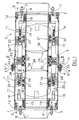
- the coupling for tubing that is illustrated in the drawings is the two valves type and it comprises a first and a second part 1 and 2 that are fastenable to each other by means of a circumferencial series of fracture screws of 3 having an intermediate segment 4 with a reduced section and therefore weakened (Fig. 1).
- Each of said parts 1 and 2 of the coupling comprises a first and a second the terminal flange 5 and 6, to the first one of which a respective tubing 8 is fastenable by means of screws 7 .
- a cylindrical duct 10 defining an axial passage for the flow of fluid that flows through the coupling extends in opposite sense, axially aligned with said tubing 8.
- a cylindrical coupling box 11 that has one end fastened to the flange 5 by means of screws 12 and that ends at the other end with the flange 6 still extends from the flange 5 .
- an external flange 51 is welded that, when the coupling is coupled, is set against a corresponding external flange 52 made up of solid piece with an annular band 53 welded around the terminal flange 6 of the part of coupling 2 and extending axially from it so as to surround the terminal flange 6 of the part of coupling 1 in sliding engagement.
- the fracture screws 3 are set as a connection of two external flanges 51 and 52.
- a disc 14 is arranged in axially sliding way on the duct 10, that it is thrust toward the right (looking at Fig. 1) by a compression spring 15, possibly substitutable by several springs coaxial to each other.
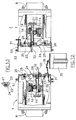
- a spherical segment valve 24 (1/4 of a sphere in the example herein reported) is hinged, than owing to the rotary-sliding motion of the toothed wheels 20 can be displaced from the opening position illustrated in Fig. 1 to the closing position illustrated in Figures 11 and 12. In this latter position the spherical back 25 of the valve is not only rotated perpendicular to the axis of the coupling but it is also pressed against one annular seal packing 26 that is embedded in a corresponding housing of flange 6.
- Each rack rod 16 ends with a piston 27 that is slidingly housed inside a respective cylinder 28 fastened to the flange 6.
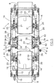
- the cylinder 28 is normally filled with oil not in pressure, than in case of feeding of the piston 27 as regards the position of Fig. 1, as it will be better explained later, can protrude at a controlled speed through a gauged hole 29 that is connected by small tubes 30 to a lateral vent opening 31 ( Figures 2 and 3).
- a stem 32 extends, that slidingly passes through the same flange 6 and engages with a lever 33 that has an end hinged in 39 on the external face of flange 6.
- the other end of lever 33 is in abutment engagement with a radial projection 34 of a segment of cylindrical duct 35 that, when the coupling is coupled, is placed in intermediate position between the ducts 10 of the two parts of the coupling and as axial connection of the same ducts 10, that is made watertight by the presence of the packings 36 ( Figures 1 and 2).
- Additional packings 37 are interposed between the segment of duct 35 and the flanges 6 of the two parts of the coupling.
- the intermediate segment of duct 35 when the coupling is coupled, serves as a locking mean so as to keep the two valves 24 in an opening position.
- a chain 38 keeps the segment of duct 35 coupled to the flange 6 of one of the two parts of the coupling ( Figures 2 and 3).
- the two valves 24 can therefore reach the position of closing and engagement with the packings 26 that is illustrated in Figures 11-13, without any possibility for the segment of duct 35 to interfere with their rotary-sliding movements.
- the intermediate section of the duct 35 is kept attached to the part 1 of the coupling by the chain 38 (Fig. 12).
Landscapes
- Engineering & Computer Science (AREA)
- General Engineering & Computer Science (AREA)
- Mechanical Engineering (AREA)
- Quick-Acting Or Multi-Walled Pipe Joints (AREA)
- Joints That Cut Off Fluids, And Hose Joints (AREA)
- Mutual Connection Of Rods And Tubes (AREA)
Description
- The present invention concerns a coupling for hydraulic tubing with emergency uncoupling and hydraulic closing in conditions of strong axial traction.
- There are known couplings for hydraulic tubing, particularly utilised in the oil field for the coupling of hoses in motion, for instance between a ship and another one, a ship and the mainland, a ship and an oil platform, in which possible strong axial traction stresses due to causes of any kind would be expected to automatically cause the uncoupling of the connection and the immediate interception of the hydraulic flow under course. In this way it is possible to prevent that an axial traction higher than the maximum limit bearable by the hosing can determine the deterioration of the same hosing.
- In particular there are known couplings that are made up of two parts that are passed through by respective axial ducts, which are connected by rigid connection means that are suitable to allow the automatic separation of the aforesaid parts in the case of an axial traction higher than a predetermined limit. At least one of said parts comprises a means for the interception of the flow of fluid that is made up of a spherical segment valve that responds to the separation movement of the two parts of the coupling with a combined motion of rotation around an axis perpendicular to the longitudinal axis of the respective axial duct and of sliding along said longitudinal axis up to the attainment of a closing position.
- A coupling of this type according to the preamble of
claim 1 is described in WO-A-99/17044 and for the aforesaid spherical segment valve it provides for at least a mechanism of rotary-sliding operation comprising at least a sliding rack rod and at least a toothed segment that are co-operating from opposite sides with at least one toothed wheel that creates a driving hinge of said valve. There are provided elastic means that through a sliding disc thrust said rack rod towards a closing position of said valve, locking means that, when the coupling is coupled, keep said valve in opening position, and cylinders and piston means connected with said rack rod in order to control the feeding speed of said rack rod towards the closing position of said valve. - The aforesaid locking means are made up of a segment of duct fastened to the other part of the coupling or freely interposed between the two parts of the coupling, against which the spherical segment valve abuts when the coupling is coupled.
- The use of said segment of duct for the locking of the valve into a closing position determines the requirement for two equally important measures: one is to avoid a discontinuity between said segment of duct and the axial ducts of the two parts of the coupling, so as to prevent that the fluid being transported invades the mechanisms responsible for the operation of the valve, consequently determining difficulty in movement, erosions, formation of rust and so on; another, not easy to combine with the previous one, is to assure that the aforesaid segment of duct brings itself in unlocking position before the closing movement of the valve has begun, so as to prevent mechanical interference between the two.
- Object of the present invention is to realise a coupling of the aforementioned type that meets both of the aforesaid requirements.
- According to the invention such object is attained with a coupling for hydraulic tubing that is made up of two parts of coupling that are passed through by respective axial ducts for the flow of fluid and are connected with each other by rigid coupling means that are suitable to allow the automatic separation of the same parts in case of an axial traction higher than a predetermined limit, at least one first part of the coupling comprising a means for the interception of the flow of fluid that is made up of a spherical segment valve that responds to the movement of separation of the two parts of the coupling with a combined motion of rotation around an axis perpendicular to the longitudinal axis of the respective axial duct and of sliding along said longitudinal axis up to the attainment of a closing position, said valve being provided with a rotary-sliding drive mechanism comprising at least one sliding rack rod and at least one toothed segment that are co-operating from opposite sides with at least one toothed wheel making up a driving hinge for said valve, and there being provided elastic means that thrust said rack rod toward a position suitable to determine the closing of said valve, locking means that, when the coupling is coupled, keep said valve in opening position, and resisting means connected with said rack rod in order to control the feeding speed of said rack rod towards the closing position of said valve, said locking means being made up of a ductsegment which is arranged as an extension of the axial duct of the first part of the coupling and against which said valve abuts when the coupling is coupled, characterised in that said duct segment is tightly set against said axial duct of the first part of the coupling, and said rack rod is suitable to operate on said duct segment in order to control its axial movement of expulsion from said first part of the coupling and in addition it is operatively connected with said valve in such a way as to control the beginning of its movement of closing only after that said axial movement of expulsion of the duct segment has determined the removal of the same duct segment from the path of the closing movement of said valve.
- Owing to this expedient the transported fluid remains confined inside the duct destined to it and it does not involve the operating mechanisms of the valve and at the same time it assures that the duct segment that maintains the valve in opening condition does not interfere in any way with the closing movement of the same valve in case of an uncoupling determined by strong axial stresses.
- Naturally, as already described in the previously recalled patent WO-A-99/17044, both parts of the coupling can be provided with a spherical segment valve with rotary-sliding movement with relative operating mechanism and in such case the characteristics that are described for the first part of the coupling must be repeated for the second part of the same coupling, that is the duct segment that is utilised for the locking of the valve of the second part of the coupling is positined in a similar way as regards the relative axial duct and it is also subjected to a movement of axial expulsion from said second part of the coupling before the aforesaid valve is controlled to execute a closing movement.
- A coupling of the latter type is illustrated as a non-limiting example in the enclosed drawings, in which
- Fig. 1 shows in axial section, in operating position; a coupling with two valves according to the present invention;
- Fig. 2 shows the aforesaid coupling in longitudinal section according to the line II-II in Fig. 1;
- Fig. 3 shows the same coupling in cross section according to the line III-III in Fig. 1;
- Fig. 4 shows a magnified detail of the same coupling in section according to the line IV-IV in Fig. 1;
- Figures 5, 6 and 7 show views similar to the ones in Figures 1, 2 and 4 at the beginning of the stage of emergency uncoupling of the two parts of the coupling;
- Figures 8, 9 and 10 show views similar to the ones in Figures 1, 2 and 4 at the beginning of the subsequent stage of closing of the valves;
- Figures 11, 12 and 13 show views similar to the ones in Figures 1, 2 and 4 at the end of the movement of closing of the valves.
- The coupling for tubing that is illustrated in the drawings is the two valves type and it comprises a first and a
second part intermediate segment 4 with a reduced section and therefore weakened (Fig. 1). - Each of said
parts terminal flange 5 and 6, to the first one of which arespective tubing 8 is fastenable by means ofscrews 7 . From the same flange 5, in correspondence of itscentral hole 9, acylindrical duct 10 defining an axial passage for the flow of fluid that flows through the coupling extends in opposite sense, axially aligned with saidtubing 8. Coaxial to theduct 10 and outside of it acylindrical coupling box 11 that has one end fastened to the flange 5 by means ofscrews 12 and that ends at the other end with theflange 6 still extends from the flange 5 . - To the
coupling box 11 of the part ofcoupling 1 anexternal flange 51 is welded that, when the coupling is coupled, is set against a correspondingexternal flange 52 made up of solid piece with anannular band 53 welded around theterminal flange 6 of the part ofcoupling 2 and extending axially from it so as to surround theterminal flange 6 of the part ofcoupling 1 in sliding engagement. Thefracture screws 3 are set as a connection of twoexternal flanges - In the
annular space 13 defined between theduct 10 and the coupling box 11 adisc 14 is arranged in axially sliding way on theduct 10, that it is thrust toward the right (looking at Fig. 1) by acompression spring 15, possibly substitutable by several springs coaxial to each other. - To the sliding
disc 14 tworack rods 16 are symmetrically fastened (Figures 1 and 2), each one of which is slidingly held by asupport 17 that is fastened inside thecoupling box 12. A similarfixed support 18 bears atoothed segment 19 with possibility of a limited axial sliding (fig. 2). With therack rods 16 andcorresponding toothed segments 19 respectivetoothed gear wheels 20 engage that for effect of the aforesaid engagement are capable to rotate aroundrespective hinges 21 that are aligned on a single axis perpendicular to the longitudinal axis of theduct 10 and of thecoupling box 12 and passing through it, as also to slide parallel to said longitudinal axis. - On the rotation hinges 21 of the
toothed wheels 20, with a small angular clearance at an angle given bypins 22 inserted inperipheral cavities 23 of the hinges 21 (Fig. 4), a spherical segment valve 24 (1/4 of a sphere in the example herein reported) is hinged, than owing to the rotary-sliding motion of thetoothed wheels 20 can be displaced from the opening position illustrated in Fig. 1 to the closing position illustrated in Figures 11 and 12. In this latter position thespherical back 25 of the valve is not only rotated perpendicular to the axis of the coupling but it is also pressed against oneannular seal packing 26 that is embedded in a corresponding housing offlange 6. - Each
rack rod 16 ends with apiston 27 that is slidingly housed inside arespective cylinder 28 fastened to theflange 6. Thecylinder 28 is normally filled with oil not in pressure, than in case of feeding of thepiston 27 as regards the position of Fig. 1, as it will be better explained later, can protrude at a controlled speed through a gaugedhole 29 that is connected bysmall tubes 30 to a lateral vent opening 31 (Figures 2 and 3). - From every
piston 27 toward the flange 6 astem 32 extends, that slidingly passes through thesame flange 6 and engages with alever 33 that has an end hinged in 39 on the external face offlange 6. The other end oflever 33 is in abutment engagement with aradial projection 34 of a segment ofcylindrical duct 35 that, when the coupling is coupled, is placed in intermediate position between theducts 10 of the two parts of the coupling and as axial connection of thesame ducts 10, that is made watertight by the presence of the packings 36 (Figures 1 and 2).Additional packings 37 are interposed between the segment ofduct 35 and theflanges 6 of the two parts of the coupling. - As shown in Fig. 2, the intermediate segment of
duct 35, when the coupling is coupled, serves as a locking mean so as to keep the twovalves 24 in an opening position. - A
chain 38 keeps the segment ofduct 35 coupled to theflange 6 of one of the two parts of the coupling (Figures 2 and 3). - The normal operating state of the coupling is the one illustrated in Figures 1, 2 and 3, where the fracture screws 3 hold the two
parts tubing 8, bothvalves 24 are open and maintained as such by their contrast with the cylindrical wall of the segment ofduct 35 and the fluid being distributed can flow without any obstacle from onetubing 8 to the other through the axial passage defined by the two alignedcylindrical ducts 10 and by the intermediate segment ofduct 35. - If in this condition one of the two tubing were to be subject to an axial traction stress higher than the allowed limit, the weakened
parts 4 of thefracture screws 3 would break, thus allowing the mutual separation of twoterminal flanges 6 from each other under the guidance of the sliding engagement realised between theannular band 53 of the second part of thecoupling 2 and theterminal flange 6 of the first part of thecoupling 1. The aforesaid guidance assures that the breaking of thescrews 3 takes place only in case of strong traction stress, thus avoiding instead undesired breaks of the screws and consequent separations of the two parts of the coupling for fatigue of the same screws as a result of small and repeated bending strains between one part and the other of the coupling. - When this happens, under the thrust of the
springs 15 the two slidingdiscs 14 force theracks 16 to move forward thus causing the subsequent feed ofpistons 27 in therespective cylinders 28; the speed of thepistons 27 feed, and therefore of theracks 16, is controlled owing to gaugedholes 29, that regulate the outflow of the oil from thecylinders 28. For effect of such feed thestems 32 force thelevers 33 to rotate around theirfulcrua 39 in order to separate theradial projections 34 of the intermediate segment ofduct 35 from two flange the 6 and therefore to determine the expulsion of the segment ofduct 35 from the twoparts - During the first part of the feeding stroke of the
racks 16 the sliding clearance existing between thetoothed segments 19 and theirsupports 18 allows thetoothed wheels 20 to rotate around their axis without sliding (Figures 5 and 6) and the rotational clearance existing between thetoothed wheels 20 and thevalves 24 prevents the rotation of thetoothed wheels 20 from being transmitted to valves 24 (Fig. 7). - The subsequent feed of the
racks 16, with thetoothed segments 19 and thepins 22 that have already got to the end of the stroke and the intermediate segment ofduct 35 substantially extracted from the two parts ofcoupling 1 and 2 (Figures 6 and 7), causes not only to the rotation but also the feed of thetoothed wheels 20 and at the same time the rotation of thevalves 24 and their sliding along the common axis of the ducts 10 (Figures 8-10). - The two
valves 24 can therefore reach the position of closing and engagement with thepackings 26 that is illustrated in Figures 11-13, without any possibility for the segment ofduct 35 to interfere with their rotary-sliding movements. With two parts of thecoupling valves 24 closed, the intermediate section of theduct 35 is kept attached to thepart 1 of the coupling by the chain 38 (Fig. 12).
Claims (7)
- Coupling for hydraulic tubing made up of two parts of coupling (1, 2) that are passed through by respective axial ducts (10) for the flow of fluid and connected with each other by rigid coupling means (3) that are suitable to allow the automatic separation of the same parts in the case of an axial traction higher than a predetermined limit, at least one first part (1, 2) of the coupling comprising means for the interception of the flow of fluid that are made up of a spherical segment valve (24) that responds to the movement of separation of two parts (1, 2) of the coupling with a combined motion of rotation around an axis perpendicular to the longitudinal axis of the respective axial duct (10) and of sliding along said longitudinal axis up to the attainment of a closing position, said valve (24) being provided with a rotary-sliding drive mechanism comprising at least one sliding rack rod (16) and at least one toothed segment (19) that are co-operating from opposite sides with at least one toothed wheel (20) that makes up a driving hinge (21) for said valve (24), and there being provided elastic means (15) that thrust said rack rod (16) towards a position that is suitable to determine the closing of said valve (24), locking means (35) that, when the coupling is coupled, keep said valve (24) in opening position, and resisting means (28, 27) connected with said rack rod (16) in order to control the feeding speed of said rack rod (16) toward the closing position of said valve (24), said locking means (35) being made up of a duct segment (35) that is arranged as an extension of the axial duct (10) of the first part of the coupling and against which said valve (24) abuts when the coupling is coupled, characterised in that said duct segment (35) is tightly set against said axial duct (10) of the first part of the coupling, and said rack rod (16) is suitable to operate on said duct segment (35) in order to control its axial movement of expulsion from said first part of the coupling and in addition is operationally connected with said valve (24) in such a way as to control the beginning of its closing movement only after said axial movement of expulsion of the duct segment (35) has determined the removal of the same duct segment (35) from the path of the closing movement of said valve (24).
- Coupling according to claim 1, characterised in that said rack rod (16) operates on said duct segment (35) through a stem (32) that is fixedly mounted to said rack rod (16) and set against a lever (33) that is suitable to produce a movement of expulsion of said duct segment (35).
- Coupling according to claim 2, characterised in that said resistance means (28, 27) comprise a piston (27) that is fastened to one end of said rack rod (16) and sliding inside a hydraulic cylinder (28) provided with a gauged hole (29) for the outflow of a hydraulic fluid that is normally not in pressure and is contained inside said cylinder (28), said stem (32) extending axially from said piston (27) inside said cylinder (28) in such way that, as a consequence of the feed of said rack rod (16), said stem (32) protrudes axially from said cylinder (28) in order to operate on said lever (33) for expulsion of said duct segment (35).
- Coupling according to claim 1, characterised in that said toothed segment (19) is supported by a fixed support (18) with limited possibility of axial sliding clearance and said valve (24) is bound to said rotation hinge (21) of said toothed wheel (20) with limited possibility of rotational clearance, so that an initial part of the feeding movement of the rack rod (16) can determine only an axial sliding of said toothed segment (19) and a rotation of said toothed wheel (20) without a simultaneous sliding movement of said toothed wheel (20) and a simultaneous rotary and sliding movement of said valve (24) take place.
- Coupling according to claim 1, characterised in that said elastic means (15) are made up of at least one compression spring (15) operating on a sliding disc (14) fastened to the other end of said rack rod (16).
- Coupling according to claim 1, characterised in that said rigid coupling means (3) are made up of fracturable screws (3) with weakened intermediate section (4).
- Coupling according to claim 6, characterised in that said fracturable screws (3) are set as a connection between an external flange (51) fastened to one of said parts (1, 2) of the coupling and another external flange (52) fastened to an external band (53) that is fastened to the other part of the coupling and extends axially from it so as to surround the opposite end of said part of the coupling in sliding engagement.
Applications Claiming Priority (2)
| Application Number | Priority Date | Filing Date | Title |
|---|---|---|---|
| IT2000MI000078A IT1316297B1 (en) | 2000-01-24 | 2000-01-24 | FITTING FOR HYDRAULIC PIPES WITH RELEASE AND HYDRAULIC CLOSURE EMERGENCY IN CONDITIONS OF STRONG AXIAL TRACTION |
| ITMI000078 | 2000-01-24 |
Publications (2)
| Publication Number | Publication Date |
|---|---|
| EP1120596A1 EP1120596A1 (en) | 2001-08-01 |
| EP1120596B1 true EP1120596B1 (en) | 2007-03-14 |
Family
ID=11443747
Family Applications (1)
| Application Number | Title | Priority Date | Filing Date |
|---|---|---|---|
| EP01200203A Expired - Lifetime EP1120596B1 (en) | 2000-01-24 | 2001-01-19 | Emergency release coupling in response to strong axial traction |
Country Status (3)
| Country | Link |
|---|---|
| EP (1) | EP1120596B1 (en) |
| ES (1) | ES2283372T3 (en) |
| IT (1) | IT1316297B1 (en) |
Families Citing this family (1)
| Publication number | Priority date | Publication date | Assignee | Title |
|---|---|---|---|---|
| EP2547580A4 (en) | 2010-05-20 | 2017-05-31 | Excelerate Energy Limited Partnership | Systems and methods for treatment of lng cargo tanks |
Family Cites Families (3)
| Publication number | Priority date | Publication date | Assignee | Title |
|---|---|---|---|---|
| US5365973A (en) * | 1993-10-25 | 1994-11-22 | Husky Corporation | Break-away concentric hose coupling |
| US5546986A (en) * | 1995-02-07 | 1996-08-20 | Clark Technology Systems, Inc. | Leakproof dual action fluid transfer valve |
| IT1295092B1 (en) * | 1997-09-29 | 1999-04-27 | Valagem Servicos E Gestao Lda | FITTING FOR PIPES WITH AUTOMATIC RELEASE AND IMMEDIATE HYDRAULIC CLOSURE IN RESPONSE TO STRONG AXIAL TRACTION |
-
2000
- 2000-01-24 IT IT2000MI000078A patent/IT1316297B1/en active
-
2001
- 2001-01-19 EP EP01200203A patent/EP1120596B1/en not_active Expired - Lifetime
- 2001-01-19 ES ES01200203T patent/ES2283372T3/en not_active Expired - Lifetime
Also Published As
| Publication number | Publication date |
|---|---|
| EP1120596A1 (en) | 2001-08-01 |
| ITMI20000078A1 (en) | 2001-07-24 |
| ITMI20000078A0 (en) | 2000-01-24 |
| ES2283372T3 (en) | 2007-11-01 |
| IT1316297B1 (en) | 2003-04-10 |
Similar Documents
| Publication | Publication Date | Title |
|---|---|---|
| CA2751446C (en) | Trigger joint | |
| US3902694A (en) | Swinging spherical gate valve and double seal quick disconnect coupling | |
| JP5718381B2 (en) | Flow control actuator device used for self-closing stop valve | |
| EP0803651B1 (en) | Fluid-controlled actuator assembly | |
| EP0006278B1 (en) | Breakaway pipe coupling | |
| US7191791B2 (en) | Device for actuating double seat valves | |
| US20030047214A1 (en) | Valve actuator system | |
| WO2018065761A1 (en) | Pipeline coupling | |
| US4519411A (en) | Emergency disconnector for fluid loading and unloading lines | |
| EP1120596B1 (en) | Emergency release coupling in response to strong axial traction | |
| US20140097363A1 (en) | Floating seal retainer | |
| EP1917450A4 (en) | Self aligning brake kit | |
| EP0023120B1 (en) | Fluid-operated actuator comprising a detachably mounted fail-safe unit | |
| CN109649664A (en) | Couple release device | |
| EP3029338B1 (en) | Valve actuator device with driving arm having a modular structure | |
| US4563941A (en) | Hydraulic actuator for control of valves | |
| EP1044341B1 (en) | Pipe fitting with automatic release and immediate water seal closing in response to a strong axial traction | |
| US4549636A (en) | Disc brakes for vehicles | |
| EP3652472B1 (en) | Actuator for slide valves | |
| US20190072205A1 (en) | Control valve for a process plant | |
| EP4063071A1 (en) | Actuating unit | |
| US8430019B2 (en) | Adjusting device | |
| EP3204277B1 (en) | Pressure balancing device for hydraulic braking systems | |
| EP0676552B1 (en) | Stop valves for pistons of self-regulating hydraulic devices | |
| EP2320166B1 (en) | Expansion valve |
Legal Events
| Date | Code | Title | Description |
|---|---|---|---|
| PUAI | Public reference made under article 153(3) epc to a published international application that has entered the european phase |
Free format text: ORIGINAL CODE: 0009012 |
|
| AK | Designated contracting states |
Kind code of ref document: A1 Designated state(s): ES FR GB IT |
|
| AX | Request for extension of the european patent |
Free format text: AL;LT;LV;MK;RO;SI |
|
| 17P | Request for examination filed |
Effective date: 20011205 |
|
| AKX | Designation fees paid |
Free format text: ES FR GB IT |
|
| REG | Reference to a national code |
Ref country code: DE Ref legal event code: 8566 |
|
| GRAP | Despatch of communication of intention to grant a patent |
Free format text: ORIGINAL CODE: EPIDOSNIGR1 |
|
| GRAS | Grant fee paid |
Free format text: ORIGINAL CODE: EPIDOSNIGR3 |
|
| RAP1 | Party data changed (applicant data changed or rights of an application transferred) |
Owner name: BORMIOLI, MARINA Owner name: BORMIOLI, LORENZO |
|
| RIN1 | Information on inventor provided before grant (corrected) |
Inventor name: BORMIOLI, LORENZO Inventor name: BORMIOLI, MARINA |
|
| GRAA | (expected) grant |
Free format text: ORIGINAL CODE: 0009210 |
|
| AK | Designated contracting states |
Kind code of ref document: B1 Designated state(s): ES FR GB IT |
|
| REG | Reference to a national code |
Ref country code: GB Ref legal event code: FG4D |
|
| REG | Reference to a national code |
Ref country code: ES Ref legal event code: FG2A Ref document number: 2283372 Country of ref document: ES Kind code of ref document: T3 |
|
| PLBE | No opposition filed within time limit |
Free format text: ORIGINAL CODE: 0009261 |
|
| STAA | Information on the status of an ep patent application or granted ep patent |
Free format text: STATUS: NO OPPOSITION FILED WITHIN TIME LIMIT |
|
| 26N | No opposition filed |
Effective date: 20071217 |
|
| REG | Reference to a national code |
Ref country code: FR Ref legal event code: PLFP Year of fee payment: 16 |
|
| REG | Reference to a national code |
Ref country code: FR Ref legal event code: PLFP Year of fee payment: 17 |
|
| REG | Reference to a national code |
Ref country code: FR Ref legal event code: PLFP Year of fee payment: 18 |
|
| PGFP | Annual fee paid to national office [announced via postgrant information from national office to epo] |
Ref country code: GB Payment date: 20200121 Year of fee payment: 20 Ref country code: ES Payment date: 20200205 Year of fee payment: 20 Ref country code: IT Payment date: 20200124 Year of fee payment: 20 |
|
| PGFP | Annual fee paid to national office [announced via postgrant information from national office to epo] |
Ref country code: FR Payment date: 20200128 Year of fee payment: 20 |
|
| REG | Reference to a national code |
Ref country code: GB Ref legal event code: PE20 Expiry date: 20210118 |
|
| PG25 | Lapsed in a contracting state [announced via postgrant information from national office to epo] |
Ref country code: GB Free format text: LAPSE BECAUSE OF EXPIRATION OF PROTECTION Effective date: 20210118 |
|
| REG | Reference to a national code |
Ref country code: ES Ref legal event code: FD2A Effective date: 20210728 |
|
| PG25 | Lapsed in a contracting state [announced via postgrant information from national office to epo] |
Ref country code: ES Free format text: LAPSE BECAUSE OF EXPIRATION OF PROTECTION Effective date: 20210120 |