EP1120592A2 - Control unit for a electromagnetic valve - Google Patents
Control unit for a electromagnetic valve Download PDFInfo
- Publication number
- EP1120592A2 EP1120592A2 EP01101114A EP01101114A EP1120592A2 EP 1120592 A2 EP1120592 A2 EP 1120592A2 EP 01101114 A EP01101114 A EP 01101114A EP 01101114 A EP01101114 A EP 01101114A EP 1120592 A2 EP1120592 A2 EP 1120592A2
- Authority
- EP
- European Patent Office
- Prior art keywords
- control unit
- ridge
- connection
- fact
- coil
- Prior art date
- Legal status (The legal status is an assumption and is not a legal conclusion. Google has not performed a legal analysis and makes no representation as to the accuracy of the status listed.)
- Withdrawn
Links
Images


Classifications
-
- F—MECHANICAL ENGINEERING; LIGHTING; HEATING; WEAPONS; BLASTING
- F16—ENGINEERING ELEMENTS AND UNITS; GENERAL MEASURES FOR PRODUCING AND MAINTAINING EFFECTIVE FUNCTIONING OF MACHINES OR INSTALLATIONS; THERMAL INSULATION IN GENERAL
- F16K—VALVES; TAPS; COCKS; ACTUATING-FLOATS; DEVICES FOR VENTING OR AERATING
- F16K31/00—Actuating devices; Operating means; Releasing devices
- F16K31/02—Actuating devices; Operating means; Releasing devices electric; magnetic
- F16K31/06—Actuating devices; Operating means; Releasing devices electric; magnetic using a magnet, e.g. diaphragm valves, cutting off by means of a liquid
- F16K31/0675—Electromagnet aspects, e.g. electric supply therefor
- F16K31/0679—Electromagnet aspects, e.g. electric supply therefor with more than one energising coil
-
- B—PERFORMING OPERATIONS; TRANSPORTING
- B60—VEHICLES IN GENERAL
- B60T—VEHICLE BRAKE CONTROL SYSTEMS OR PARTS THEREOF; BRAKE CONTROL SYSTEMS OR PARTS THEREOF, IN GENERAL; ARRANGEMENT OF BRAKING ELEMENTS ON VEHICLES IN GENERAL; PORTABLE DEVICES FOR PREVENTING UNWANTED MOVEMENT OF VEHICLES; VEHICLE MODIFICATIONS TO FACILITATE COOLING OF BRAKES
- B60T15/00—Construction arrangement, or operation of valves incorporated in power brake systems and not covered by groups B60T11/00 or B60T13/00
- B60T15/02—Application and release valves
- B60T15/04—Driver's valves
- B60T15/14—Driver's valves influencing electric control means
Definitions
- the present invention concerns a control unit of a valve mechanism, which has an electromagnetic coil.
- control units for electromagnetically operable hydraulic valves are encountered ever more frequently in technology, particularly in antilock systems in the automotive industry.
- a particular faculty of application of the said control unit exists in the automotive industry in antilock systems (ABS) and antiskid devices.
- ABS antilock systems
- the control unit monitors, for example, the skid behaviour of the wheel of a passenger vehicle. If, for example, there is a risk that the wheel might lock during the process of braking, this is detected by sensors on the wheel and transmitted to the control unit ; to this control unit are linked several electromagnetically operable hydraulic valves.
- valves are arranged in units (valve blocks) and in order to avoid situations in the vehicle which can no longer be controlled, the control unit controls the brake circuit in such a way that before a wheel locks, the force of braking is reduced by means of bringing about the opening and closing of the hydraulic valve, until the danger of a wheel lock has been removed.
- the valve blocks which consist of several electromagnetic valves have, as a rule, a valve reception body, a housing, as well as a cover for closing the housing.
- the housing has openings for the reception of the contact pins of the electromagnetic coils, which are located in the housing. These contact pins are fastened directly to the printed circuit boards, which transmit signals for the control of the hydraulic valves.
- valve block with several electromagnetically operable hydraulic valves, which has a cover with electrical conductors and conductor strips made from brass sheet and located in the said cover, the conductors being fitted with contact elements which, on the cover being fitted on the valve block, are brought into contact with the contact elements of the electromagnetic valve coils.
- a drawback of the aforementioned state-of-the-art resides in the fact that an elastic suspension of the coils is needed for the state-of-the-art control unit and that the holes in the housing cover for the reception of the coil contacts to the printed circuit boards exhibit play, making the said opening difficult to cover.
- connection device can have an insulating ridge, which supports the connecting ridge and where the insulating ridge has a second undulating sector. This insulating ridge increases the stiffness of the spring-mounted connecting ridge.
- the coil can have a spool holder with collars, where the connecting ridge has a first step, which is cast into one of the collars.
- the insulating ridge can be a part of the collar and project beyond the latter, where the insulating ridge has a first area enclosing the first step and a second area formed around a second step where the second undulating sector connects the first area with the second area.
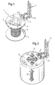
- Fig. 1 shows coil 1 which has a coil holder 2 for the reception of a hydraulic valve.
- the coil 1 has at its upper end a collar 3 and at its lower end a collar 4 and a wire winding 5.
- To the upper end 3 are formed in two electrically conducting pins 6 on which is inserted the connection device 7 for connection to the printed circuit board (not shown) which has a wire connection sector 7a and a contact sector 7b.
Abstract
Description
- The present invention concerns a control unit of a valve mechanism, which has an electromagnetic coil.
- Such control units for electromagnetically operable hydraulic valves are encountered ever more frequently in technology, particularly in antilock systems in the automotive industry. A particular faculty of application of the said control unit exists in the automotive industry in antilock systems (ABS) and antiskid devices. In order to control the various systems, the control unit monitors, for example, the skid behaviour of the wheel of a passenger vehicle. If, for example, there is a risk that the wheel might lock during the process of braking, this is detected by sensors on the wheel and transmitted to the control unit ; to this control unit are linked several electromagnetically operable hydraulic valves. These valves are arranged in units (valve blocks) and in order to avoid situations in the vehicle which can no longer be controlled, the control unit controls the brake circuit in such a way that before a wheel locks, the force of braking is reduced by means of bringing about the opening and closing of the hydraulic valve, until the danger of a wheel lock has been removed.
- The valve blocks, which consist of several electromagnetic valves have, as a rule, a valve reception body, a housing, as well as a cover for closing the housing. The housing has openings for the reception of the contact pins of the electromagnetic coils, which are located in the housing. These contact pins are fastened directly to the printed circuit boards, which transmit signals for the control of the hydraulic valves.
- It is important in the case of such control units that the complete control unit should be shielded from outside influences, so that good sealing of the said unit is ensured during assembly. In doing so, the fitting of the housing on the valve block presents problems, because only very small tolerances are available for the fastening and connection of the coils to the electronic printed circuit boards.
- DE 37 42 320 A1 describes a valve block with several electromagnetically operable hydraulic valves, which has a cover with electrical conductors and conductor strips made from brass sheet and located in the said cover, the conductors being fitted with contact elements which, on the cover being fitted on the valve block, are brought into contact with the contact elements of the electromagnetic valve coils.
- USP 5 374 114 describes an electro-hydraulic pressure control device with several electromagnetically operable hydraulic valves where the coils are flexibly arranged flexibly on a carrier via an elastic plastic fixing device.
- A drawback of the aforementioned state-of-the-art resides in the fact that an elastic suspension of the coils is needed for the state-of-the-art control unit and that the holes in the housing cover for the reception of the coil contacts to the printed circuit boards exhibit play, making the said opening difficult to cover.
- It is accordingly the purpose of the present invention to make possible the economical and simple construction of a control unit for a tightly sealable valve mechanism, whilst conserving large tolerances.
- According to the present invention, this purpose is accomplished by the fact that the electromagnetic coil is connected electrically and mechanically to the control unit via a connection device, which has at least one spring-mounted connecting ridge.
- This has the advantage that during assembly, that is to say, during the fitting of the housing containing the electronic unit on the hydraulic unit via the spring-mounted connecting ridge, a greater degree of clearance is possible. The electrically conducting spring-mounted connecting ridge serves to compensate axial and radial forces when the coils are connected to the control unit, that is to say, when the housing is fitted on the hydraulic unit. The connecting ridge serves simultaneously as an electrical contact for connection to the printed circuit board and for the compensation of inaccuracies in manufacture.
- For improved spring action, the spring-mounted connecting ridge can have a first undulating sector, which is arranged between a wire connection sector and a contact sector. Furthermore, the connecting ridge can be arranged substantially at right angles to the axis of the electromagnetic coil where the contact pin lies parallel to the axis of the coil.
- In this way, clearance during manufacture can be increased in the direction of insertion of the contact pin.
- To achieve a greater degree of stiffness of the spring-mounted connecting ridge, the connection device can have an insulating ridge, which supports the connecting ridge and where the insulating ridge has a second undulating sector. This insulating ridge increases the stiffness of the spring-mounted connecting ridge.
- Furthermore, the connecting ridge can be fitted to a coil end. The contact pin and the connecting ridge can substantially lie at right angles to one another.
- Furthermore, the coil can have a spool holder with collars, where the connecting ridge has a first step, which is cast into one of the collars.
- Furthermore, the insulating ridge can be a part of the collar and project beyond the latter, where the insulating ridge has a first area enclosing the first step and a second area formed around a second step where the second undulating sector connects the first area with the second area.
- Furthermore, the contact ridge and the contact pin can be connected with one another via a sealing shoulder. This sealing shoulder makes it possible to seal the control unit after the housing has been pierced by the contact pin.
- Below, an example of an embodiment of the invention is more fully explained by reference to the appended drawings :
- Fig. 1 shows the electromagnetic coil with the connection device and the contact pin :
- Fig. 2 shows the coil from Fig 1 in a metal housing ;
- Fig. 3a shows a part of the connection device and of the contact pin;
- Fig. 3b is an enlarged section of the connection device and contact pin and
- Fig. 4 shows in section a valve block with incorporated coils ;
-
- Fig. 1 shows coil 1 which has a coil holder 2 for the reception of a hydraulic valve. The coil 1 has at its upper end a
collar 3 and at its lower end a collar 4 and a wire winding 5. To theupper end 3 are formed in two electrically conductingpins 6 on which is inserted the connection device 7 for connection to the printed circuit board (not shown) which has a wire connection sector 7a and acontact sector 7b. - Fig. 2 shows the electromagnetic coil after it has been fitted during the process of manufacture in a metal housing 8. Furthermore, the ends 9 of the coil winding are shown, which are wound on the electrically conducting
pin 6 and so form an electrical contact between the wire winding 5 and a connecting device 7. The connection device 7 consists of an undulatingconnection ridge 10, thecontact pin 11 and electrically conductingpins 6. Thiscontact pin 11 passes through an opening of a printed circuit board and is fastened to the said board, where the position of thecontact pin 11 is laid down in relation to the printed circuit board. Through the undulating connection ridge 10 a flexible area now forms in an axial direction represented by thearrow 12 and also a flexible area in a radial direction represented by thearrow 13. - Fig. 3a represents the electrically conducting part of the connection device 7. The electrically conducting
pin 6 runs parallel with thecontact pin 11, where theconnection ridge 10 has alamina 23 with anundulating sector 14a, afirst step 25 and asecond step 26. - Fig. 3b is an enlargement of a part of the connection device 7. On the
collar 3 of the coil are arranged both the electrically conductingpins 6, which form the electrical connection between thepin 6 and thecontact pin 11. Parallel to thelamina 23 runs theinsulating ridge 22 with a second undulatingsector 14b, which is made of a plastic material. For better comprehension, the sector in Fig 3a is shown cross-hatched. On thecollar 3 is furthermore arranged afirst area 15 which has twoopenings 16 for the reception of the electrically conductingpins 6. Thefirst area 15 is connected with asecond area 17 through theinsulating ridge 22, which has a sealingshoulder 24 and which completely encloses thesecond step 26 of thecontact pin 11 and has acollar 18. Thiscollar 18 serves as a seal, when thecontact pin 11 is introduced into an aperture provided for that purpose in the printed circuit board. By means of these plastic parts, the spring-mounted connection between the coil and thecontact pin 11 is stiffened. At the lower end, thesecond area 17 has a supportingsurface 19. - Fig. 4 shows in section a part of the control unit. The coils 1 with winding 5 and the
housing 21 are sprayed with a layer of thermoelastic rubber 20 (such as Santoprene). In the section shown, it is possible to see that theundulating sector 14a has been cast into the thermoelastic rubber coating where theelectrical pin 6 is connected to the coil and thecontact pin 11 is introduced into a printed circuit board (not shown). Furthermore, the supportingsurface 19 is shown on the underside of thecollar 18 as it extends from the thermoelastic rubber coating and forms a pressure surface. It is possible to fit an object on thispressure surface 19 to form a thrust bearing when thecontact pin 11 is introduced into the printed circuit board. - Summarising, the invention makes it possible to create a control unit of a valve mechanism which, through an electrically conducting, spring-mounted connection ridge, forms a flexible contact between the coil and the printed circuit board. This makes possible greater manufacturing tolerances for the position of the coils in relation to the contact pins during the process of manufacture.
Claims (9)
- A control unit of a valve mechanism with an electromagnetic coil (1), characterised by the fact that the electromagnetic coil (1) is electrically and mechanically connected to the control unit via a connection device (7) which has a spring-mounted connection ridge (10).
- A control unit according to Claim 1, characterised by the fact that the connection ridge (10) has a first undulating sector (14a) which is arranged between a wire connection sector (7a) and a contact sector (7b).
- A control unit according to Claim 1 or Claim 2, characterised by the fact that the said connection ridge (10) is substantially arranged at right angles to the axis of the electromagnetic coil (1).
- A control unit according to one of the Claims 1 to 3, characterised by the fact that the connection device (7) has an insulating ridge (22) which supports the connection ridge (10)
- A control unit according to Claim 4, characterised by the fact that the insulating ridge (22) has a second undulating sector (14b)
- A control unit according to one of the Claims from 1 to 5, characterised by the fact that the connection ridge (10) is located at an end of a coil.
- A control unit according to one of the Claims from 1 to 6, characterised by the fact that the coil (1) has a coil carrier (2) with collars (3, 4) where the connection ridge (10) has a first step (25) which is cast into one of the collars (3, 4)
- A control unit according to Claim 7, characterised by the fact that the insulating ridge (22) is a part of the collar, projects beyond the latter and has a first area (15) which encloses the first step (25) and a second area (17) which is formed around a second step (26) where the second undulating sector (14b) connects the first area (15) with the second area (17)
- A control unit according to one of the Claims from 1 to 8, characterised by the fact that the connection between the contact ridge (10) and the contact pin (11) has a sealing shoulder (17)
Applications Claiming Priority (2)
| Application Number | Priority Date | Filing Date | Title |
|---|---|---|---|
| DE10003055A DE10003055B4 (en) | 2000-01-25 | 2000-01-25 | Control unit of a valve mechanism |
| DE10003055 | 2000-01-25 |
Publications (3)
| Publication Number | Publication Date |
|---|---|
| EP1120592A2 true EP1120592A2 (en) | 2001-08-01 |
| EP1120592A3 EP1120592A3 (en) | 2002-11-13 |
| EP1120592A9 EP1120592A9 (en) | 2003-02-19 |
Family
ID=7628638
Family Applications (1)
| Application Number | Title | Priority Date | Filing Date |
|---|---|---|---|
| EP01101114A Withdrawn EP1120592A3 (en) | 2000-01-25 | 2001-01-18 | Control unit for a electromagnetic valve |
Country Status (4)
| Country | Link |
|---|---|
| US (1) | US6476703B2 (en) |
| EP (1) | EP1120592A3 (en) |
| KR (1) | KR100744957B1 (en) |
| DE (1) | DE10003055B4 (en) |
Cited By (3)
| Publication number | Priority date | Publication date | Assignee | Title |
|---|---|---|---|---|
| DE102007013877A1 (en) | 2007-03-20 | 2008-10-02 | Hydraulik-Ring Gmbh | Cover for electromagnetic valve, has electrical contact surface, particularly electrical arc of contact, that is provided on its rear side for connecting through electrical plug contacts at electromagnet |
| GB2479740A (en) * | 2010-04-20 | 2011-10-26 | Eaton Ind Mfg Gmbh | Remote-control resetting device |
| WO2012123534A1 (en) * | 2011-03-15 | 2012-09-20 | Continental Automotive Gmbh | Connector pin |
Families Citing this family (12)
| Publication number | Priority date | Publication date | Assignee | Title |
|---|---|---|---|---|
| DE10029279A1 (en) * | 2000-06-14 | 2001-12-20 | Bosch Gmbh Robert | Two-part magnetic coil/solenoid manufacturing method e.g. for fuel injection valve of IC engine, involves pushing hollow cylindrical coil carrier consisting of insulating material, onto housing body |
| US6947981B2 (en) * | 2002-03-26 | 2005-09-20 | Hewlett-Packard Development Company, L.P. | Flexible data replication mechanism |
| JP2004179498A (en) * | 2002-11-28 | 2004-06-24 | Minebea Co Ltd | Coil bobbin structure |
| DE10340134A1 (en) * | 2003-09-01 | 2005-06-16 | Kendrion Binder Magnete Gmbh | Electromagnetic valve is made up of separate valve, electromagnetic operating system and electrical connection modules, valve having cylindrical connecting section at back, on to which other modules fit |
| DE102005041240B4 (en) * | 2005-08-31 | 2009-04-30 | Tyco Electronics Belgium Ec N.V. | Solenoid valve control device and hydraulic control device |
| TWM310433U (en) * | 2006-09-08 | 2007-04-21 | Donsun Solar Technology Co Ltd | Light emitting device with magnetron switch |
| EP1970919B1 (en) * | 2007-03-13 | 2013-01-02 | Nass Magnet GmbH | Electromagnetic coil |
| TWM359783U (en) * | 2009-02-26 | 2009-06-21 | Delta Electronics Inc | Inductor |
| CN101901661B (en) * | 2009-05-26 | 2011-12-21 | 浙江三花股份有限公司 | Electromagnetic coil device |
| CN102913661B (en) * | 2011-08-04 | 2016-05-18 | 浙江三花股份有限公司 | Contact pin cladding and there is the coil injection molding part of this contact pin cladding |
| US20170287627A1 (en) * | 2016-03-29 | 2017-10-05 | Eaton Corporation | Current transformer apparatus that is mountable to a circuit board |
| CN113775807A (en) * | 2021-08-20 | 2021-12-10 | 中汽创智科技有限公司 | Solenoid valve coil fixed knot constructs and solenoid valve |
Citations (2)
| Publication number | Priority date | Publication date | Assignee | Title |
|---|---|---|---|---|
| US3510823A (en) * | 1968-04-29 | 1970-05-05 | Joseph J Cervenka | Fastener or terminal lug device and method of making same |
| DE3039457A1 (en) * | 1980-10-18 | 1982-05-27 | Brown, Boveri & Cie Ag, 6800 Mannheim | Coil body with formed coupling socket - has external connections made using latching plug and built-in socket |
Family Cites Families (11)
| Publication number | Priority date | Publication date | Assignee | Title |
|---|---|---|---|---|
| DE3742320A1 (en) * | 1987-12-14 | 1989-06-22 | Teves Gmbh Alfred | Valve unit |
| JP2522042B2 (en) * | 1989-04-24 | 1996-08-07 | 富士電機株式会社 | Terminal device |
| DE3926454C2 (en) * | 1989-08-10 | 1998-02-26 | Teves Gmbh Alfred | Valve block, especially for slip-controlled hydraulic brake systems |
| DE4015564A1 (en) * | 1990-05-15 | 1991-11-21 | Philips Patentverwaltung | Transformer with connections protected from external damage - has meander-shaped connection between terminal pin and internal winding |
| ES2061278T3 (en) * | 1991-01-15 | 1994-12-01 | Teves Gmbh Alfred | ELECTRO-HYDRAULIC PRESSURE REGULATOR DEVICE. |
| EP0499670B1 (en) * | 1991-02-20 | 1995-10-11 | Siemens Aktiengesellschaft | Valve control device |
| DE19518519C2 (en) * | 1995-05-19 | 1998-07-16 | Siemens Ag | Valve control unit |
| DE19532763C2 (en) * | 1995-09-05 | 1998-07-16 | Siemens Ag | Valve control device for controlling a valve for a hydraulic fluid |
| DE19545011A1 (en) * | 1995-10-05 | 1997-04-10 | Teves Gmbh Alfred | Valve block for motor vehicle pneumatic or hydraulic brake system control device |
| JPH09126207A (en) * | 1995-10-31 | 1997-05-13 | Aisin Seiki Co Ltd | Pressure controller |
| US5999079A (en) * | 1996-09-30 | 1999-12-07 | Siemens Aktiengesellschaft | Magnet coil with radial terminal pins and the method for manufacturing the coil |
-
2000
- 2000-01-25 DE DE10003055A patent/DE10003055B4/en not_active Expired - Fee Related
-
2001
- 2001-01-18 EP EP01101114A patent/EP1120592A3/en not_active Withdrawn
- 2001-01-22 KR KR1020010003537A patent/KR100744957B1/en not_active IP Right Cessation
- 2001-01-24 US US09/769,236 patent/US6476703B2/en not_active Expired - Fee Related
Patent Citations (2)
| Publication number | Priority date | Publication date | Assignee | Title |
|---|---|---|---|---|
| US3510823A (en) * | 1968-04-29 | 1970-05-05 | Joseph J Cervenka | Fastener or terminal lug device and method of making same |
| DE3039457A1 (en) * | 1980-10-18 | 1982-05-27 | Brown, Boveri & Cie Ag, 6800 Mannheim | Coil body with formed coupling socket - has external connections made using latching plug and built-in socket |
Cited By (5)
| Publication number | Priority date | Publication date | Assignee | Title |
|---|---|---|---|---|
| DE102007013877A1 (en) | 2007-03-20 | 2008-10-02 | Hydraulik-Ring Gmbh | Cover for electromagnetic valve, has electrical contact surface, particularly electrical arc of contact, that is provided on its rear side for connecting through electrical plug contacts at electromagnet |
| GB2479740A (en) * | 2010-04-20 | 2011-10-26 | Eaton Ind Mfg Gmbh | Remote-control resetting device |
| CN102934194A (en) * | 2010-04-20 | 2013-02-13 | 伊顿工业制造有限公司 | Remote-control resetting device |
| CN102934194B (en) * | 2010-04-20 | 2015-04-29 | 伊顿工业制造有限公司 | Remote-control resetting device |
| WO2012123534A1 (en) * | 2011-03-15 | 2012-09-20 | Continental Automotive Gmbh | Connector pin |
Also Published As
| Publication number | Publication date |
|---|---|
| US6476703B2 (en) | 2002-11-05 |
| US20010019920A1 (en) | 2001-09-06 |
| KR20010074524A (en) | 2001-08-04 |
| KR100744957B1 (en) | 2007-08-02 |
| DE10003055A1 (en) | 2001-08-09 |
| EP1120592A9 (en) | 2003-02-19 |
| EP1120592A3 (en) | 2002-11-13 |
| DE10003055B4 (en) | 2004-09-09 |
Similar Documents
| Publication | Publication Date | Title |
|---|---|---|
| US6476703B2 (en) | Control unit of a valve mechanism | |
| US5853231A (en) | Pressure control device | |
| US6007162A (en) | Hydraulic motor-vehicle brake system with anti-locking control and automatic actuation of the brakes for the control of the drive and/or travel dynamics | |
| KR100533221B1 (en) | Hydraulic brake control | |
| EP1282544B1 (en) | Braking device comprising an integrated pressure sensor module | |
| US8104357B2 (en) | Connection unit for a pressure measuring cell | |
| JP3644457B2 (en) | Valve control device | |
| US8534641B2 (en) | Connecting element and associated fluid assembly | |
| CN101428608B (en) | Solenoid-valve unit for an electropneumatic controller, especially a pilot-control unit of an electropneumatic pressure modulator of a vehicle | |
| KR101697077B1 (en) | Connecting element and related fluid assembly | |
| US6241489B1 (en) | Internal electrical connector for a hydraulic control unit | |
| US5988772A (en) | Hydraulic control apparatus | |
| KR101418683B1 (en) | Electronic control apparatus for vehicle using water proof type housing sealing and method thereof | |
| KR20010110742A (en) | Electromagnetic valve support | |
| JP3617022B2 (en) | Hydraulic control device | |
| KR20120077210A (en) | Pressure sensor | |
| US20080060889A1 (en) | Braking pressure control unit for vehicle braking system | |
| KR20010076163A (en) | An apparatus for controlling pressure | |
| JPH09193788A (en) | Brake pressure control device | |
| US5904180A (en) | Pressure control device integral formed the electric controller | |
| US20010048244A1 (en) | Valve control unit | |
| US5977852A (en) | Valve control device for controlling a valve for a pressure fluid | |
| US6336818B1 (en) | Electrical connector for connection between coil and printed circuit board in automotive anti-lock braking system | |
| JPH1059151A (en) | Liquid pressure controller | |
| JPH1059153A (en) | Liquid pressure controller |
Legal Events
| Date | Code | Title | Description |
|---|---|---|---|
| PUAI | Public reference made under article 153(3) epc to a published international application that has entered the european phase |
Free format text: ORIGINAL CODE: 0009012 |
|
| AK | Designated contracting states |
Kind code of ref document: A2 Designated state(s): AT BE CH CY DE DK ES FI FR GB GR IE IT LI LU MC NL PT SE TR |
|
| AX | Request for extension of the european patent |
Free format text: AL;LT;LV;MK;RO;SI |
|
| PUAL | Search report despatched |
Free format text: ORIGINAL CODE: 0009013 |
|
| AK | Designated contracting states |
Kind code of ref document: A3 Designated state(s): AT BE CH CY DE DK ES FI FR GB GR IE IT LI LU MC NL PT SE TR |
|
| AX | Request for extension of the european patent |
Free format text: AL;LT;LV;MK;RO;SI |
|
| RIC1 | Information provided on ipc code assigned before grant |
Free format text: 7F 16K 31/06 A, 7F 16K 27/00 B |
|
| RAP1 | Party data changed (applicant data changed or rights of an application transferred) |
Owner name: F.C.I. - FRAMATOME CONNECTORS INTERNATIONAL |
|
| 17P | Request for examination filed |
Effective date: 20030505 |
|
| AKX | Designation fees paid |
Designated state(s): AT BE CH CY DE DK ES FI FR GB GR IE IT LI LU MC NL PT SE TR |
|
| 17Q | First examination report despatched |
Effective date: 20070119 |
|
| RAP1 | Party data changed (applicant data changed or rights of an application transferred) |
Owner name: FCI |
|
| RAP1 | Party data changed (applicant data changed or rights of an application transferred) |
Owner name: FCI |
|
| 18D | Application deemed to be withdrawn |
Effective date: 20110510 |
|
| STAA | Information on the status of an ep patent application or granted ep patent |
Free format text: STATUS: THE APPLICATION IS DEEMED TO BE WITHDRAWN |
|
| R18D | Application deemed to be withdrawn (corrected) |
Effective date: 20101228 |