EP1120573A2 - Hydraulic drive unit with counter balancing valve - Google Patents
Hydraulic drive unit with counter balancing valve Download PDFInfo
- Publication number
- EP1120573A2 EP1120573A2 EP00311691A EP00311691A EP1120573A2 EP 1120573 A2 EP1120573 A2 EP 1120573A2 EP 00311691 A EP00311691 A EP 00311691A EP 00311691 A EP00311691 A EP 00311691A EP 1120573 A2 EP1120573 A2 EP 1120573A2
- Authority
- EP
- European Patent Office
- Prior art keywords
- circuits
- return
- circuit
- main
- passages
- Prior art date
- Legal status (The legal status is an assumption and is not a legal conclusion. Google has not performed a legal analysis and makes no representation as to the accuracy of the status listed.)
- Granted
Links
Images


Classifications
-
- E—FIXED CONSTRUCTIONS
- E02—HYDRAULIC ENGINEERING; FOUNDATIONS; SOIL SHIFTING
- E02F—DREDGING; SOIL-SHIFTING
- E02F9/00—Component parts of dredgers or soil-shifting machines, not restricted to one of the kinds covered by groups E02F3/00 - E02F7/00
- E02F9/20—Drives; Control devices
- E02F9/22—Hydraulic or pneumatic drives
- E02F9/2264—Arrangements or adaptations of elements for hydraulic drives
- E02F9/2267—Valves or distributors
-
- E—FIXED CONSTRUCTIONS
- E02—HYDRAULIC ENGINEERING; FOUNDATIONS; SOIL SHIFTING
- E02F—DREDGING; SOIL-SHIFTING
- E02F9/00—Component parts of dredgers or soil-shifting machines, not restricted to one of the kinds covered by groups E02F3/00 - E02F7/00
- E02F9/20—Drives; Control devices
- E02F9/22—Hydraulic or pneumatic drives
- E02F9/226—Safety arrangements, e.g. hydraulic driven fans, preventing cavitation, leakage, overheating
-
- E—FIXED CONSTRUCTIONS
- E02—HYDRAULIC ENGINEERING; FOUNDATIONS; SOIL SHIFTING
- E02F—DREDGING; SOIL-SHIFTING
- E02F9/00—Component parts of dredgers or soil-shifting machines, not restricted to one of the kinds covered by groups E02F3/00 - E02F7/00
- E02F9/20—Drives; Control devices
- E02F9/22—Hydraulic or pneumatic drives
- E02F9/2264—Arrangements or adaptations of elements for hydraulic drives
- E02F9/2271—Actuators and supports therefor and protection therefor
-
- F—MECHANICAL ENGINEERING; LIGHTING; HEATING; WEAPONS; BLASTING
- F15—FLUID-PRESSURE ACTUATORS; HYDRAULICS OR PNEUMATICS IN GENERAL
- F15B—SYSTEMS ACTING BY MEANS OF FLUIDS IN GENERAL; FLUID-PRESSURE ACTUATORS, e.g. SERVOMOTORS; DETAILS OF FLUID-PRESSURE SYSTEMS, NOT OTHERWISE PROVIDED FOR
- F15B11/00—Servomotor systems without provision for follow-up action; Circuits therefor
- F15B11/02—Systems essentially incorporating special features for controlling the speed or actuating force of an output member
- F15B11/04—Systems essentially incorporating special features for controlling the speed or actuating force of an output member for controlling the speed
- F15B11/044—Systems essentially incorporating special features for controlling the speed or actuating force of an output member for controlling the speed by means in the return line, i.e. "meter out"
- F15B11/0445—Systems essentially incorporating special features for controlling the speed or actuating force of an output member for controlling the speed by means in the return line, i.e. "meter out" with counterbalance valves, e.g. to prevent overrunning or for braking
-
- F—MECHANICAL ENGINEERING; LIGHTING; HEATING; WEAPONS; BLASTING
- F15—FLUID-PRESSURE ACTUATORS; HYDRAULICS OR PNEUMATICS IN GENERAL
- F15B—SYSTEMS ACTING BY MEANS OF FLUIDS IN GENERAL; FLUID-PRESSURE ACTUATORS, e.g. SERVOMOTORS; DETAILS OF FLUID-PRESSURE SYSTEMS, NOT OTHERWISE PROVIDED FOR
- F15B2211/00—Circuits for servomotor systems
- F15B2211/30—Directional control
- F15B2211/305—Directional control characterised by the type of valves
- F15B2211/30505—Non-return valves, i.e. check valves
-
- F—MECHANICAL ENGINEERING; LIGHTING; HEATING; WEAPONS; BLASTING
- F15—FLUID-PRESSURE ACTUATORS; HYDRAULICS OR PNEUMATICS IN GENERAL
- F15B—SYSTEMS ACTING BY MEANS OF FLUIDS IN GENERAL; FLUID-PRESSURE ACTUATORS, e.g. SERVOMOTORS; DETAILS OF FLUID-PRESSURE SYSTEMS, NOT OTHERWISE PROVIDED FOR
- F15B2211/00—Circuits for servomotor systems
- F15B2211/40—Flow control
- F15B2211/405—Flow control characterised by the type of flow control means or valve
- F15B2211/40515—Flow control characterised by the type of flow control means or valve with variable throttles or orifices
-
- F—MECHANICAL ENGINEERING; LIGHTING; HEATING; WEAPONS; BLASTING
- F15—FLUID-PRESSURE ACTUATORS; HYDRAULICS OR PNEUMATICS IN GENERAL
- F15B—SYSTEMS ACTING BY MEANS OF FLUIDS IN GENERAL; FLUID-PRESSURE ACTUATORS, e.g. SERVOMOTORS; DETAILS OF FLUID-PRESSURE SYSTEMS, NOT OTHERWISE PROVIDED FOR
- F15B2211/00—Circuits for servomotor systems
- F15B2211/40—Flow control
- F15B2211/42—Flow control characterised by the type of actuation
- F15B2211/428—Flow control characterised by the type of actuation actuated by fluid pressure
-
- F—MECHANICAL ENGINEERING; LIGHTING; HEATING; WEAPONS; BLASTING
- F15—FLUID-PRESSURE ACTUATORS; HYDRAULICS OR PNEUMATICS IN GENERAL
- F15B—SYSTEMS ACTING BY MEANS OF FLUIDS IN GENERAL; FLUID-PRESSURE ACTUATORS, e.g. SERVOMOTORS; DETAILS OF FLUID-PRESSURE SYSTEMS, NOT OTHERWISE PROVIDED FOR
- F15B2211/00—Circuits for servomotor systems
- F15B2211/40—Flow control
- F15B2211/46—Control of flow in the return line, i.e. meter-out control
-
- F—MECHANICAL ENGINEERING; LIGHTING; HEATING; WEAPONS; BLASTING
- F15—FLUID-PRESSURE ACTUATORS; HYDRAULICS OR PNEUMATICS IN GENERAL
- F15B—SYSTEMS ACTING BY MEANS OF FLUIDS IN GENERAL; FLUID-PRESSURE ACTUATORS, e.g. SERVOMOTORS; DETAILS OF FLUID-PRESSURE SYSTEMS, NOT OTHERWISE PROVIDED FOR
- F15B2211/00—Circuits for servomotor systems
- F15B2211/60—Circuit components or control therefor
- F15B2211/61—Secondary circuits
- F15B2211/613—Feeding circuits
-
- F—MECHANICAL ENGINEERING; LIGHTING; HEATING; WEAPONS; BLASTING
- F15—FLUID-PRESSURE ACTUATORS; HYDRAULICS OR PNEUMATICS IN GENERAL
- F15B—SYSTEMS ACTING BY MEANS OF FLUIDS IN GENERAL; FLUID-PRESSURE ACTUATORS, e.g. SERVOMOTORS; DETAILS OF FLUID-PRESSURE SYSTEMS, NOT OTHERWISE PROVIDED FOR
- F15B2211/00—Circuits for servomotor systems
- F15B2211/70—Output members, e.g. hydraulic motors or cylinders or control therefor
- F15B2211/705—Output members, e.g. hydraulic motors or cylinders or control therefor characterised by the type of output members or actuators
- F15B2211/7058—Rotary output members
-
- F—MECHANICAL ENGINEERING; LIGHTING; HEATING; WEAPONS; BLASTING
- F15—FLUID-PRESSURE ACTUATORS; HYDRAULICS OR PNEUMATICS IN GENERAL
- F15B—SYSTEMS ACTING BY MEANS OF FLUIDS IN GENERAL; FLUID-PRESSURE ACTUATORS, e.g. SERVOMOTORS; DETAILS OF FLUID-PRESSURE SYSTEMS, NOT OTHERWISE PROVIDED FOR
- F15B2211/00—Circuits for servomotor systems
- F15B2211/70—Output members, e.g. hydraulic motors or cylinders or control therefor
- F15B2211/715—Output members, e.g. hydraulic motors or cylinders or control therefor having braking means
-
- F—MECHANICAL ENGINEERING; LIGHTING; HEATING; WEAPONS; BLASTING
- F15—FLUID-PRESSURE ACTUATORS; HYDRAULICS OR PNEUMATICS IN GENERAL
- F15B—SYSTEMS ACTING BY MEANS OF FLUIDS IN GENERAL; FLUID-PRESSURE ACTUATORS, e.g. SERVOMOTORS; DETAILS OF FLUID-PRESSURE SYSTEMS, NOT OTHERWISE PROVIDED FOR
- F15B2211/00—Circuits for servomotor systems
- F15B2211/80—Other types of control related to particular problems or conditions
- F15B2211/86—Control during or prevention of abnormal conditions
- F15B2211/8609—Control during or prevention of abnormal conditions the abnormal condition being cavitation
Definitions
- the present invention relates to a hydraulic drive unit for driving a hydraulic motor which is utilized as a traveling device in a construction machine.
- the invention is concerned with a hydraulic drive unit capable of preventing the occurrence of cavitation while a hydraulic motor is OFF.
- a hydraulic motor M is connected to an oil pressure source comprising a pump and a tank via a pair of main circuits 1 and 2, a counter-balancing valve 3 disposed halfway of the main circuits 1 and 2, and ports P1 and P2. Further, a return circuit 64 is disposed between the two main circuits 1 and 2, a pair of check valves 5 and 6 are disposed halfway of the return circuit 64 so as to be capable of being opened and closed, and a low pressure circuit 7 is connected to the return circuit 64 at a position between the two check valves 5 and 6. A leakage circuit from the motor M is connected to the low pressure circuit 7, which in turn is connected to the tank side via tank ports T1 and T2.
- the pump port P1 is connected to the pump side and the other pump port P2 connected to the tank side through a change-over valve (not shown), allowing an oil pressure to be fed from the pump port P1.
- the counter-balancing valve 3 changes over to its left-hand position, whereby an oil pressure is fed from the main circuit 1 to the hydraulic motor M, causing the motor to rotate in the forward direction.
- Return oil from the hydraulic motor M is returned to the tank side via the other main circuit 2, counter-balancing valve 3, and pump port P2.
- the motor rotates by the force of inertia.
- the hydraulic motor M sucks in oil in the main circuit 1 and discharges the oil into the other main circuit 2, that is, performs a so-called pumping operation.
- the main circuit 1 becomes negative in pressure
- the hydraulic motor M sucks in air in the main circuit 1, and cavitation occurs, thereby generating a low-noise for the hydraulic motor M. Therefore, for preventing the occurrence of cavitation caused by vacuum action, oil is sucked in from the tank side by means of the low pressure circuit 7 and a hydraulic operating oil is fed to the hydraulic motor M via the return circuit 64, check valve 5 and main circuit 1.
- the low pressure circuit 7 is required to have a pressure and a flow rate both sufficient to effect the supply of oil.
- the low pressure circuit is a drain line, it is impossible to set its pressure so high, and for ensuring the required oil pressure and flow rate it is necessary to alter not only the hydraulic motor but also the circuit and the entire system used.
- the hydraulic drive unit is used for a traveling device in a small-sized construction machine for example, it is impossible to alter even the circuit and system used in the machine body and it is the present situation that the improvement in deceleration feeling of the hydraulic motor and the prevention of low-noise occurrence due to cavitation are not effected to a satisfactory extent.
- the present invention provides a hydraulic drive unit comprising a pair of main circuits each connecting an oil pressure source with a hydraulic motor; a counter-balancing valve disposed halfway of the main circuits so as to be capable of being changed over from one position to another, said counter-balancing valve being provided with a pair of discharge passages and a pair of return passages, both of which are adapted to be opened and closed for the main circuits, a pair of first check valves disposed halfway of the discharge passages, a pair of orifices disposed halfway of the return passages, and a pair of branch passages which are connected to the discharge passages on upstream sides of the first check valves and selectively connected to the by-pass circuit; return circuits each connected to the main circuits in a position therebetween; a pair of second check valves disposed halfway of the return circuits; and a by-pass circuit connected to the return circuits in a position between the second check valves.
- the present invention provides a hydraulic drive unit comprising a pair of main circuits each connecting an oil pressure source with a hydraulic motor and having first main circuits and second main circuits which are in parallel with each other; first check valves disposed halfway of the first main circuits; a counter-balancing valve disposed halfway of the second main circuits so as to be capable of being changed over from one position to another, said counter-balancing valve being provided with a pair of branch passages selectively opening and closing the second main circuits for the first by-pass circuit, a pair of return passages opened and closed for the second main circuits, and a pair of orifices disposed halfway of the return passages; return circuits each connected to the main circuits in a position therebetween; a pair of second check valves disposed halfway of the return circuits; and a first by-pass circuit connected to the return circuits in a position between the second check valves.
- the present invention provides a hydraulic drive unit comprising a pair of main circuits each connecting an oil pressure source with a hydraulic motor and having first main circuits and second main circuits which are in parallel with each other; first check valves disposed halfway of the first main circuits; a counter-balancing valve disposed halfway of the second main circuits so as to be capable of being changed over from one position to another, said counter-balancing valve being provided with a pair of return passages opened and closed for the second main circuits, and a pair of orifices disposed halfway of the return passages; return circuits each connected to the main circuits in a position therebetween; a pair of second check valves disposed halfway of the return circuits; a first by-pass circuit connected to the return circuits in a position between the second check valves; second by-pass circuits connected to the main circuits in a position therebetween in parallel with the return circuits; and a change-over valve disposed halfway of the second by-pass circuits and at the same time of changing-over thereof,
- the present invention provides a hydraulic drive unit comprising a pair of main circuits each connecting an oil pressure source with a hydraulic motor; a counter-balancing valve disposed halfway of the main circuits so as to be capable of being changed over from one position to another, said counter-balancing valve being provided with a pair of discharge passages and a pair of return passages, both of which are adapted to be opened and closed for the main circuits, a pair of first check valves disposed halfway of the discharge passages, a pair of orifices disposed halfway of the return passages, and a pair of branch passages which are connected to the discharge passages on upstream sides of the first check valves and are selectively connected to the by-pass circuit; return circuits each connected to the main circuits in a position therebetween; a high pressure selection valve disposed halfway of the return circuits so as to be capable of being changed over from one position to another; and a by-pass circuit connected to the return circuits on a downstream side of the high pressure valve so as to be capable
- auxiliary passages which communicate with a brake cylinder-side circuit so as to be capable of being opened and closed are connected to the branch passages of the counter-balancing valve.
- the counter-balancing valve consists of a spool type valve body inserted slidably into a valve hole of a valve body, said valve hole being provided with a land groove having a suitable width which opens and closes the by-pass circuit and the branch circuits in accordance with a stroke of the counter-balancing valve.
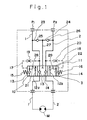
- Fig. 1 shows a hydraulic circuit for a hydraulic drive unit according to an embodiment of the present invention
- Figs. 2 to 4 show a concrete structure of a hydraulic drive unit which utilizes the hydraulic circuit illustrated in Fig. 1.
- a counter-balancing valve 3 is disposed halfway of the main circuits 1 and 2 so as to be capable of being changed over from one position to another, the counter-balancing valve 3 being provided with a pair of discharge passages 10, 11 and a pair of return passages 12a, 12b which discharge and return passages are adapted to be opened and closed for the main circuits 1 and 2 and also provided with a pair of first check valves 13 and 14 halfway of the discharge passages 10 and 11, respectively, and a pilot circuit 17 provided with a spring 15 and an orifice 19 and a pilot circuit 18 provided with a spring 16 and an orifice 20 are disposed respectively on both sides of the counter-balancing valve 3.
- the counter-balancing valve 3 is further provided with a pair of branch passages 21 and 22 which are connected respectively to upstream sides of the first check valves 13 and 14, return circuits 23 and 24 are connected to the main circuits 1 and 2, respectively, and a pair of second check valves 25 and 26 which permit the flow of oil from the main circuits 1 and 2 are disposed halfway of the return circuits 23 and 24, respectively.
- a by-pass circuit 27 is connected at one end thereof to the return circuits 23 and 24 at a position between the second check valves 25 and 26, while the opposite end of the by-pass circuit 27 is opened and closed selectively for the paired branch passages 21 and 22.
- Orifices 28 and 29 are formed halfway of the paired return passages 12a and 12b, respectively.
- Pump ports P1 and P2 of the main circuits 1 and 2 respectively are connected to a pump side and a tank side selectively through a change-over valve.
- the pressure oil further opens the first check valve 13 and is fed to the hydraulic motor M via the main circuit 1 on the down stream side to rotate the motor in the forward direction.
- Return oil from the hydraulic motor M is returned to the tank side via the other main circuit 2-return passage 12a - orifice 28 - pump port P2.
- the change-over valve is returned to the neutral state to cut off the tank ports P1 and P2 from the oil pressure source. Consequently, there no longer is any pilot pressure from the pilot circuit 17 and the counter-balancing valve 3 is returned gradually to its neutral state in Fig. 1 with the restoring force of the right-hand spring 16.
- the by-pass circuit 27 is in communication with the first branch passage 21, so that the hydraulic motor M shifts in its rotation stopping direction while being slowed down. But at the beginning of turning OFF of the oil pressure source the motor M rotates by virtue of inertia, sucks in oil in the main circuit 1 and discharge the oil into the other main circuit 2.
- the hydraulic motor M performs a so-called pumping operation for a certain time.
- the main circuit 1 side is pressure-reduced and tends to become negative in pressure, and the internal pressure of the other main circuit 2 becomes high in the presence of the orifice 28, thereby giving a braking force to the hydraulic motor M.
- the pressure oil passed through the orifice 28 acts on the right-hand second check valve 26 through the return circuit 24, causing the valve 26 to open.
- the pressure oil in the main circuit 2 is fed to the main circuit 1 via the second check valve 26 - return circuit 24- by-pass circuit 27 - branch passage 21 - discharge passage 10 - first check valve 13, and the pressure oil in the main circuit 1 is circulated to the hydraulic motor M, whereby the generation of a negative pressure in the main circuit 1 is prevented to prevent the occurrence of cavitation.
- Fig. 2 illustrates a hydraulic drive unit based on the hydraulic circuit shown in Fig. 1 according to the present invention. The details of its structure will be described below, in which the same components as in Fig. 1 will be identified by the same reference numerals as in Fig. 1.
- a valve body 30 Within a valve body 30 are formed a pair of main circuits 1 and 2 as passages which are connected to pump ports P1 and P2 and also connected to a hydraulic motor M.
- a valve hole 31 is formed in the valve body 30 so as to communicate with the main circuits 1 and 2 perpendicularly thereto and a counter-balancing valve 3 which changes over the main circuits 1 and 2 through opening and closing motions is inserted slidably into the valve hole 31.
- a pair of return circuits 23 and 24 as passages communicating with the main circuits 1 and 2 respectively through the counter-balancing valve 3 and also through the valve hole 31, as well as a by-pass circuit 27 as a passage connected to the return circuits 23 and 24, are formed within the valve body 30.
- Halfway of the return circuits 23 and 24 are disposed a pair of second check valves 25 and 26 so as to be capable of being opened and closed, the second check valves 25 and 26 each comprising a poppet type valve body, a, and a spring, b.
- the counter-balancing valve 3 comprises a hollow spool 32, a discharge passage 10 and a return passage 12a both formed within the spool 32, and a pair of first check valves 13 and 14 disposed respectively within the discharge passage 10 and the return passage 12a so as to be capable of being opened and closed, the first check valves 13 and 14 each comprising a valve body, C, and a spring, d. Further, in the spool 32 are formed a pair of branch passages 21 and 22 which permit the discharge passage 10 and the return passage 12a to be opened and closed for the by-pass circuit 27 upstream of the first check valves 13 and 14.
- the discharge passage 10 and the return passage 12a are used on the discharge side and the return side selectively.
- the spool 32 is on the right-hand side in Fig. 2
- pressure oil is fed to the discharge passage 10 and the return passage 12a is connected to the tank side to let the pressure oil return.
- a pair of pressure chambers 33 and 34 are formed on both sides of the spool 32.
- the pressure chambers 33 and 34 are in communication respectively with the main circuits 1 and 2 on the pump ports P1 and P2 through the pilot circuits 17 and 18, with orifices 19 and 20 being formed in the pilot circuits 17 and 18, respectively.
- a pair of springs 15 and 16 are disposed respectively within the pressure chambers 33 and 34 and on both sides of the spool 32.
- Fig. 2 the counter-balancing valve 3 is held in a neutral state, pressure oil is not fed, and the hydraulic motor M is blocked by the first check valves 13 and 14 and is OFF. If in this state the pump port P1 is connected to the pump side and the pump port P2 is connected to the tank side, pressure oil is fed to the main circuit 1. Consequently, pilot pressure acts on the left-hand pressure chamber 33 through the pilot circuit 17 and the spool 32 moves rightwards against the right-hand spring. In this state, one discharge passage 10 is open to the by-pass circuit 27 through the left-hand branch passage 21 and the right-hand return passage 12a is open to the return-side main circuit 2 through the right-hand branch passage 22.
- a clearance gap regulated with an end notch is formed between the right-hand branch passage 22 and the main circuit 2, and the clearance gap serves as an orifice 28 restricted by degrees.
- the pump ports P1 and P2 are cut off from the oil pressure source.
- the spool 32 is still in its right-hand position as in Fig. 4 though the spool 32 moves leftwards in degrees.
- the left-hand first check valve 13 is opened, allowing the hydraulic motor M to shift to OFF while slowing down.
- the pumping operation of the hydraulic motor M is performed, whereby pressure oil of one main circuit 1 is sucked in and the main circuit 1 is reduced in pressure, while the pressure oil is discharged to the other main circuit 2, the inside of which becomes high in pressure in the presence of the orifice 28, thereby giving a braking force to the hydraulic motor M.
- the pressure oil passed through the orifice 28 acts on the right-hand second check valve 26 through the return circuit 24, causing the valve 26 to open.
- the pressure oil present in the main circuit 2 is fed to the main circuit 1 circulatively via the return circuit 24 - second check valve 26 - by-pass circuit 27 - branch passage 21 - discharge passage 10 - first check valve 13 to prevent the internal pressure of the main circuit 1 from becoming negative and prevent the occurrence of cavitation.
- the spool 32 moves toward its original position under the action of the right-hand spring 16 and is restored to its state shown in Fig. 2, whereby the hydraulic motor M is blocked completely and turns OFF.
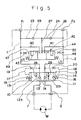
- Fig. 5 illustrates a hydraulic circuit for a hydraulic drive unit according to another embodiment of the present invention.
- this hydraulic circuit in addition to the circuit components used in the embodiment illustrated in Fig. 1, a second by-pass circuit is provided in parallel and a change-over valve is provided in the second by-pass circuit.
- a second by-pass circuit is provided in parallel and a change-over valve is provided in the second by-pass circuit.
- the same components as in the embodiment illustrated in Fig. 1 will be identified by the same reference numerals as in Fig. 1.
- a counter-balancing valve 3 is disposed halfway of the main circuits 1 and 2 so as to be capable of being changed over from one position to another, the counter-balancing valve 3 being provided with a pair of discharge passages 10, 11 and a pair of return passages 12a, 12b which discharge and return passages are adapted to be opened and closed for the main circuits 1 and 2 and also provided with a pair of fist check valves 13 and 14 disposed halfway of the discharge passages 10 and 11 respectively, and a pilot circuit 17 provided with a spring 15 and an orifice 19 and a pilot circuit 18 provided with a spring 16 and an orifice 20 are disposed respectively on both sides of the counter-balancing valve 3.
- Return circuits 23 and 24 are connected between the paired main circuits 1 and 2 and a pair of second check valves 25 and 26 which permit the flow of oil from the main circuits 1 and 2 are disposed halfway of the return circuits 23 and 24, respectively.
- a first by-pass circuit 27 is connected to the return circuits 23 and 24 at a position between the second check valves 23 and 24.
- second by-pass circuits 40 and 41 are connected between the main circuits 1 and 2 in parallel with the return circuits 23 and 24, and a change-over valve 42 adapted to be changed over from one position to another with an internal pressure of one of the main circuits 1 and 2 is disposed halfway of the second by-pass circuits 40 and 41. With operation of the change-over valve 42 the first by-pass valve 27 is opened and closed selectively for the second by-pass circuits 40 and 41.
- the change-over valve 42 is provided with a pair of by-pass ports 43 and 44, and a spring 45 and a pilot circuit 47 connected to the main circuit 1, as well as a spring 46 and a pilot circuit 48 connected to the main circuit 2, are disposed respectively on both sides of the change-over valve 42, with orifices 49 and 50 being formed within the pilot circuits 47 and 48, respectively.
- the constructions and operations of the main circuits 1 and 2, counter-balancing valve 3, return circuits 23 and 24, by-pass circuit 27, and hydraulic motor M are substantially the same as in the previous embodiment illustrated in Fig. 1.
- the check valve 26 is opened through the right-hand return circuit 24 and the high-pressure oil present in the main circuit 2 is introduced into the first by-pass circuit 27 and is further introduced into the main circuit 1 through the by-pass port 43 in the change-over valve 42 and further through the second by-pass circuit 40, thereby preventing the occurrence of a negative pressure in the main circuit 1 and also preventing the occurrence of cavitation.
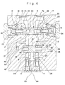
- Fig. 6 shows a hydraulic drive unit based on the hydraulic circuit illustrated in Fig. 5 according to the present invention. Since a basic structure thereof is the same as in the embodiment illustrated in Fig. 1, the same components as in Fig. 1 are identified by the same reference numerals as in Fig. 1 and explanations thereof will be omitted.
- a valve body 30 Within a valve body 30 are formed a pair of passages 53 and 54 which are connected to main circuits 1 and 2, respectively, and which are also connected to return circuits 23 and 24 through second check valves 25 and 26, respectively.
- a valve hole 51 is in communication with the passages 53 and 54 perpendicularly thereto and the change-over valve 42 constituted by a spool 52 is inserted slidably into the valve hole 51.
- the change-over valve 42 and the valve hole 51 are disposed in parallel with the return circuits 23 and 24 and the change-over valve 42 functions to connect a by-pass circuit 27 to the passages 53 and 54 selectively.
- Pilot circuits 47 and 48 are in communication with valve hole portions of the valve hole 51 located on both sides of the change-over valve 42, with the opposite ends of the pilot circuits 47 and 48 being open to the passages 53 and 54, respectively.
- the passages 53 and 54 are common oil passages for the circuits 23, 24 and the circuits 40, 41, shown in Fig. 5.
- Annular grooves serving as by-pass ports 43 and 44 are formed in the spool 52.
- the pilot pressure is exerted on the right-hand side of the change-over valve 42 through the pilot circuit 48, causing the change-over valve 42 to move leftwards.
- the by-pass port 43 is open and so is the check valve 26, so that the high-pressure oil provided from the main circuit 2 is fed to the main circuit 1 via passage 54 - check valve 26 - return circuit 24 - by-pass circuit 27 - by-pass port 43 - passage 53-discharge passage 10 and first check valve 13 in the counter-balancing valve 3 to prevent the occurrence of cavitation in the main circuit 1.
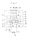
- Fig. 7 is a circuit diagram for a hydraulic drive unit according to a further embodiment of the present invention, which is a slight modification of the main circuits shown in Fig. 1.
- Main circuits 1 and 2 used in this embodiment are provided halfway with parallel first main circuits la, 2a and second main circuits 1b, 2b, and first check valves 13 and 14 are disposed in the first main circuits 1a and 2a, respectively.
- the first check valves 13 and 14 of the counter-balancing valve 3 are provided in the first main circuits 1a and 2a, respectively.
- an oil pressure source and a hydraulic motor M are connected together via a pair of main circuits 1 and 2 which can be utilized on a discharge side and a return side selectively.
- the main circuits 1 and 2 have parallel first main circuits la, 2a and second main circuits 1b, 2b, first check valves 13 and 14 are disposed halfway of the first main circuits la and 2a, respectively, and a counter-balancing valve 3 is disposed halfway of the second main circuits 1b and 2b so as to be capable of being changed over from one position to another.
- the counter:balancing valve 3 is provided with a pair of branch passages 21, 22 and a pair of return passages 12a, 12b which branch and return passages are adapted to be opened and closed for the second main circuits 1b and 2b, and further provided with restrictions 28 and 29.
- a spring 15 and a pilot circuit 17 connected to the second main circuit 1b, as well as a spring 16 and a pilot circuit 18 connected to the second main circuit 2b, are disposed respectively on both sides of the counter-balancing valve 3.
- return circuits 23 and 24 are connected to the main circuits 1 and 2 respectively, and a pair of second check valves 25 and 26 which permit the flow of oil from the main circuits 1 and 2 are disposed halfway of the return circuits 23 and 24.
- a by-pass circuit 27 is connected at one end thereof to the return circuits 23 and 24 at a position between the second check valves 25 and 26 and the opposite end of the by-pass circuit 27 is opened and closed selectively for the paired branch circuits 21 and 22.
- the counter-balancing valve 3 changes over to its left-hand position in Fig. 7, so that pressure oil is fed to the hydraulic motor M via the first main circuit la and the first check valve 13 and return oil from the hydraulic motor M is returned to the tank side via the other main circuit 2, return passage 12a and restriction 28.
- Other structural points, as well as functions and effects, are the same as in the embodiment illustrated in Fig. 1.
- Fig. 8 is a circuit diagram for a hydraulic drive unit according to a still further embodiment of the present invention.
- This embodiment like the embodiment illustrated in Fig. 7, is a slight modification of the main circuits 1, 2 and counter-balancing valve 3 used in the hydraulic circuit of Fig. 5.
- main circuits 1 and 2 are provided with first main circuits 1a, 2a and second main circuits 1b, 2b, and the first check valves 13 and 14 shown in Fig. 5 are disposed in the first main circuits 1a and 2a, respectively. More specifically, in the hydraulic circuit for a hydraulic drive unit illustrated in Fig.
- an oil pressure source and a hydraulic motor M are connected together via a pair of main circuits 1 and 2 which can be utilized on a discharge side and a return side selectively.
- the main circuits 1 and 2 are provided with parallel first main circuits 1a, 2a and second main circuits 1b, 2b, and first check valves 13 and 14 are disposed halfway of the first main circuits 1a and 2a, respectively.
- a counter-balancing valve 3 is disposed halfway of the second main circuits 1b and 2b so as to be capable of being changed over from one position to another, the counter-balancing valve 3 being provided with a pair of return passages 12a and 12b which are adapted to be opened and closed for the second main circuits 1b and 2b, respectively, and also provided with restrictions 28 and 29.
- a first by-pass circuit 27 is connected to the return circuits 23 and 24 at a position between the second check valves 25 and 26 and second by-pass circuits 40 and 41 are connected between the paired main circuits 1 and 2 in parallel with the return circuits 23 and 24.
- a change-over valve 42 adapted to be changed over its position with the internal pressure of one of the main circuits 1 and 2 is disposed halfway of the second by-pass circuits 40 and 41, and in accordance with operation of the change-over valve 42 the first by-pass circuit 27 is opened and closed selectively for the second by-pass circuit 40 or 41.
- a land groove may be formed in the valve hole 31 as in a hydraulic drive unit illustrated in Fig. 14 which will be described later.
- both by-pass circuit 27 and branch circuit can open widely through the land groove, thus permitting sufficient flow of the hydraulic actuating oil and thereby permitting an effective prevention of the occurrence of cavitation.
- Fig. 9 illustrates a hydraulic circuit according to a still further embodiment of the present invention and Figs. 10 to 13 illustrate a concrete structure of a hydraulic drive unit which utilizes this hydraulic circuit.
- a counter-balancing valve 3 is disposed halfway of the main circuits 1, 2 and so as to be capable of being changed over from one position to another, the counter-balancing valve 3 being provided with a pair of discharge passages 10, 11 and a pair of return passages 12a, 12b which discharge and return passages are adapted to be opened and closed for the main circuits 1 and 2 and also provided with a pair of first check valves 13 and 14 disposed halfway of the discharge passages 10 and 11, respectively, and a spring 15 and a pilot circuit 17 having an orifice 19, as well as a spring 16 and a pilot circuit 18 having an orifice 20, are disposed respectively on both sides of the counter-balancing valve 3.
- a pair of branch passage 21, 22 and a pair of auxiliary circuits 131, 132, which are connected upstream of the first check valves 13 and 14, are provided in the counter-balancing valve 3.
- Return circuits 23 and 24 are connected to the main circuits 1 and 2, respectively, and a high pressure selection valve 4 is disposed halfway of the return circuits 23 and 24, the high pressure selection valve 4 being adapted to change over its position with a pilot pressure provided from the main circuit 1 or 2 and permitting the flow of oil from the main circuit 1 or 2 located on the return side.
- a by-pass circuit 27 is connected at one end thereof to the return circuits 23 and 24 on a downstream side of the high pressure selection valve 4 and the opposite end of the by-pass circuit 27 is opened and closed selectively for the paired branch passages 21 and 22.
- the high pressure selection valve 4 has a neutral position and two right and left positions and is provided with pilot circuits 23a and 24a which are opposed to springs 151 and 152 disposed on both sides and which receive pilot pressures from the main circuits 1 and 2.
- the high pressure selection valve 4 is also provided with passages 153 and 154 which come into communication with the by-pass circuit 27 at the time of change-over of the return circuits 23 and 24.
- a brake cylinder 105 in a brake mechanism which controls the hydraulic motor M.
- the brake cylinder 105 is connected to drain lines T1 and T2 via circuit 133, counter-balancing valve 3 and circuit 134. Upon changing over of the counter-balancing valve 3 the drain lines T1 and T2 are cut off and the brake cylinder 105 is connected to the auxiliary circuit 131 or 132.
- Orifices 29 and 28 are formed halfway of the paired return passages 12a and 12b, respectively. Further, pump ports P1 and P2 of the main circuits 1 and 2 respectively are connected to the pump side and the tank side selectively through a change-over valve.
- the high pressure selection valve 4 changes over to its left-hand position against the spring 152 by virtue of a pilot pressure from the pilot circuit 23a.
- the counter-balancing valve 3 changes over to its left-hand position in the figure against the spring 16.
- the discharge passage 10 located at the left-hand position is connected to the main circuit 1
- the branch passage 21 is connected to the by-pass circuit 27
- the auxiliary passage 131 connects to the circuit 133
- the return passage 12a comes into communication with the main circuit 2. Consequently, the pressure oil from the pump port P1 is fed to the hydraulic motor M via discharge passage 10 - first check valve 13 - main circuit 1, causing the hydraulic motor M to rotate in the forward direction.
- Return oil from the hydraulic motor M is returned to the tank side via the main circuit 2 - return passage 12a - orifice 29 - pump port P2.
- the oil conducted to the auxiliary circuit 131 is introduced into the brake cylinder 105 via the circuit 133 to release the brake.
- pressure oil is fed to the pump port P2 and the pump port P1 is connected to the tank side. In this case there are performed operations merely reverse to the above operations.
- the change-over valve is returned to its neutral state to cut off the pump ports P1 and P2 from the oil pressure source.
- the counter-balancing valve 3 is returned gradually to its neutral state shown in Fig. 9 with the restoring force of the right-hand spring 16.
- the by-pass circuit 27 is in communication with the first branch passage 21. Consequently, the hydraulic motor M shifts to its turning OFF direction while being slowed down. But at the beginning of turning OFF of the oil pressure source the motor still rotates by virtue of inertia.
- the pumping operation of the hydraulic motor M is performed for a certain time and the pressure of the main circuit 1 side is reduced and tends to become negative, while the internal pressure of the other main circuit 2 becomes high in the presence of the orifice 29, thereby giving a braking force to the hydraulic motor M.
- the pressure oil passed through the orifice 29 acts as a pilot pressure via the pilot circuit 24a, causing the high pressure selection valve 4 to change over to its right-hand position and connecting the return circuit 24 to the by-pass circuit 27.
- the pressure oil present in the main circuit 2 is fed to the main circuit 1 via the return circuit 24 - by-pass circuit 27 - branch passage 21 - discharge passage 10 - first check valve 13 and the pressure oil in the main circuit 1 is circulated to the hydraulic motor M, whereby the occurrence of a negative pressure in the main circuit 1 and the occurrence of cavitation are prevented.
- Pressure oil is also fed to the brake cylinder 105 via the auxiliary passage 131 and circuit 133 to keep the brake released.
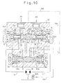
- Fig. 10 illustrates a hydraulic drive unit based on the hydraulic circuit shown in Fig. 9. The details of its structure will be described below, in which the same components as in Fig. 9 are identified by the same reference numerals as in Fig. 9.
- a valve body 30 Within a valve body 30 are formed a pair of main circuits 1 and 2 as passages connected to oil pressure source-side pump ports P1, P2 and also connected to a hydraulic motor M.
- a valve hole 140 communicating with the main circuits 1 and 2 perpendicularly thereto is formed in the valve body 30 and a counter-balancing valve 3 which changes over the main circuits 1 and 2 for opening and closing motions is inserted slidably into the valve hole 140.
- valve body 30 Within the valve body 30 are further formed a pair of return circuits 23 and 24 as passages communicating respectively with the main circuits 1 and 2 via the counter-balancing valve 3 and the valve hole 140, as well as a by-pass circuit 27 as a passage connected to the return circuits 23 and 24.
- a spool type high pressure selection valve 4 is inserted movably halfway of the return circuits 23 and 24.
- left and right pilot circuits 23a, 24a, and springs 151 and 152 are mounted on the left and right sides, respectively, of the valve body.
- a hollow spool 141 In the counter-balancing valve 3 there are provided a hollow spool 141, a discharge passage 10 and a return passage 12a both formed within the spool 141, and a pair of first check valves 13 and 14 each comprising a valve body and a spring, the first check valves 13 and 14 being inserted into the discharge passage 10 and the return passage 12a respectively so as to be capable of being opened and closed.
- a pair of branch passages 21 and 22 which cause the discharge passage 10 and the return passage 12a to be opened and closed for the by-pass circuit 27 upstream of the first check valves 13 and 14.
- the discharge passage 10 and the return passage 12a are used on the discharge side and the return side selectively.
- the spool 141 is at its right-hand position in Fig. 10
- pressure oil is fed to the discharge passage 10 and the return passage 12a is connected to the tank side for the return of pressure oil.
- a pair of pressure chambers 143 and 144 are formed on both sides of the spool 32 and are in communication respectively with pump port P1-, P2-side main circuits 1 and 2 via pilot circuits 17 and 18, with orifices 19 and 20 being formed within the pilot circuits 17 and 18, respectively.
- a pair of springs 15 and 16 are mounted within the pressure chambers 143 and 144, respectively, and on both sides of the spool 141.
- one discharge passage 10 opens to the by-pass circuit 27 through the left-hand branch passage 21 and the right-hand return passage 12a opens to the return-side main circuit 2 through the right-hand branch passage 22.
- the clearance gap serves as an orifice 28.
- the hydraulic motor M rotates in the forward direction with the pressure oil in the main circuit 1 and the pressure oil returned from the hydraulic motor M is returned to the tank via the other main circuit 2 - orifice 28 - branch passage 22 - return passage 12a - pump port P2.
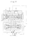
- the pump ports P1 and P2 are cut off from the oil pressure source.
- the spool 141 still occupies the right-hand position, as shown in Fig. 12 though the spool 141 moves leftwards in degrees.
- the left-hand first check valve 13 located on the left-hand side is opened, allowing the hydraulic motor M to shift to an OFF state while slowing down.
- the pumping operation of the hydraulic motor M is performed, whereby pressure oil of one main circuit 1 is sucked in and the main circuit 1 is reduced in pressure, while the pressure oil is discharged to the other main circuit 2, the inside of which becomes high in pressure in the presence of the orifice 28, thereby giving a braking force to the hydraulic motor M.
- the pressure oil passed through the orifice 28 acts on the right-hand side of the high pressure selection valve 4 from the return circuit 24 through the pilot circuit 24a, causing the valve 4 to move leftwards. Therefore, connecting the return circuit 24 to the by-pass circuit 27, as shown in Fig.
- the pressure oil present in the main circuit 2 is circulated to the main circuit 1 via the return circuit 24 - by-pass circuit 27 - branch passage 21 - discharge passage 10 - first check valve 13, thereby preventing the occurrence of a negative pressure in the main circuit 1 and preventing the occurrence of cavitation.
- the spool 141 moves toward its original position under the action of the right-hand spring 16 and is restored to its state shown in Fig. 9, so that the hydraulic motor M is blocked completely and turns OFF.
- Fig. 13 illustrates a hydraulic drive unit according to a still further embodiment of the present invention, which is not provided with a brake mechanism and hence not provided with the circuit 133 connected to the brake cylinder 105.
- Other structural points, as well as functions and effects, are the same as in the embodiment illustrated in Fig. 9.
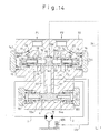
- Figs. 14 to 16 illustrate a hydraulic drive unit according to a still further embodiment of the present invention.
- This hydraulic drive unit is basically the same as the hydraulic drive unit illustrated in Fig. 10 and based on the hydraulic circuit of Fig. 9. A different point is that a land groove 60 is formed in the valve hole 140.
- this hydraulic drive unit will be described below, in which the same components as in Fig. 10 will be identified by the same reference numerals as in Fig. 10 and explanations thereof will be omitted.
- a valve body 30 Within a valve body 30 are formed pump ports P1 and P2 on an oil pressure source side and a pair of main circuits 1 and 2 which are connected to a hydraulic motor M.
- a valve hole 140 which communicates with the main circuits 1 and 2 perpendicularly thereto is formed in the valve body 30 and a valve body of a spool type counter-balancing valve 3 which changes over the main circuits 1 and 2 through opening and closing motions is inserted slidably into the valve hole 140.
- a land groove 60 having a suitable width is formed centrally in the inner periphery of the valve hole 140.
- a discharge passage 10 located on one side opens to the by-pass circuit 27 through the left-hand branch passage 21 and the land groove 60, while a return passage 12a located on the other right-hand side opens to the return-side main circuit 2 through the right-hand branch passage 22.
- a restriction 28 by the land of the spool 141 is formed between the right-hand branch passage 22 and the main circuit 2.
- the oil pressure thereof causes the left-hand first check valve 13 to open, allowing the pressure oil to be conducted to the main circuit 1 on the inflow side of the hydraulic motor M.
- the pressure oil in the main circuit 1 is also conducted to a pilot circuit 23a through a return circuit 23, causing a high pressure selection valve 4 to move rightwards to connect the by-pass circuit 27 to the return circuit 23.
- the pressure oil conducted to the by-pass circuit 27 is also conducted to a brake cylinder 105 through a circuit 133.
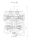
- the pump ports P1 and P2 are cut off from the oil pressure source.
- the spool 141 still occupies its right-hand position as in Fig. 15 though the spool 141 moves leftwards in degrees.
- the left-hand first check valve 13 located on the left-hand side is opened, allowing the hydraulic motor M to shift to an OFF state while slowing down.
- the pumping operation of the hydraulic motor M is performed, whereby one main circuit 1 is reduced its pressure, while the internal pressure of the other main circuit 2 becomes high in the presence of the orifice 28, thereby giving a braking force to the hydraulic motor M.
- the pressure oil passed through the orifice 28 acts on the right-hand side of the high pressure selection valve 4 from a return circuit 24 through a pilot circuit 24a, causing the valve 4 to move leftwards and connecting the return circuit 24 to the by-pass circuit 27. Consequently, as shown in Fig.
- the pressure oil present in the main circuit 2 is circulated to the main circuit 1 via the return circuit 24 - by-pass circuit 27 - land groove 60 - branch passage 21 - discharge passage 10 - first check valve 13 to prevent the internal pressure of the main circuit 1 from becoming negative and prevent the occurrence of cavitation.
- the by-pass circuit 27 and the branch passage 21 are widely open and communicate with each other, allowing a large amount of the hydraulic actuating oil to flow and thereby preventing the oil flow from becoming deficient.
- the spool 141 moves toward its original position under the action of the right-hand spring 16 and is restored to its state shown in Fig. 14, whereby the hydraulic motor M is blocked completely and turns OFF.
- Fig. 16 shows examples of the land groove 60.
- a land groove shown in Figs. 16(A) and (B) is an annular groove formed in the inner periphery of the valve hole 140 in the valve body 20 and having a suitable width in the longitudinal direction. It is substantially the same as that shown in Fig. 14.
- a land groove shown in Fig. 16(C) comprises two or more annular grooves, a, b, formed spacedly from each other in the longitudinal direction.
- a land groove 60 shown in Figs. 16(D) and (E) comprises two annular grooves, a, b, and a lateral groove, c, which provides communication between the two annular grooves, a, b.
- the land groove 60 is not specially limited insofar as it can provide communication in a large flow path area between the by-pass circuit 27 and the branch circuits 21, 22.
Abstract
Description
- The present invention relates to a hydraulic drive unit for driving a hydraulic motor which is utilized as a traveling device in a construction machine. Particularly, the invention is concerned with a hydraulic drive unit capable of preventing the occurrence of cavitation while a hydraulic motor is OFF.
- As this type of a hydraulic drive unit there is known, for example, such a hydraulic circuit as shown in Fig. 17.
- In this hydraulic circuit, a hydraulic motor M is connected to an oil pressure source comprising a pump and a tank via a pair of
main circuits counter-balancing valve 3 disposed halfway of themain circuits return circuit 64 is disposed between the twomain circuits check valves return circuit 64 so as to be capable of being opened and closed, and a low pressure circuit 7 is connected to thereturn circuit 64 at a position between the twocheck valves - For rotating the hydraulic motor M in a forward direction for example, the pump port P1 is connected to the pump side and the other pump port P2 connected to the tank side through a change-over valve (not shown), allowing an oil pressure to be fed from the pump port P1. At this time, with a pilot pressure, the
counter-balancing valve 3 changes over to its left-hand position, whereby an oil pressure is fed from themain circuit 1 to the hydraulic motor M, causing the motor to rotate in the forward direction. Return oil from the hydraulic motor M is returned to the tank side via the othermain circuit 2,counter-balancing valve 3, and pump port P2. - When the change-over valve is changed over to its neutral position, the pilot pressure is extinguished, the
counter-balancing valve 3 returns to its neutral position, and hence the supply of the pressure oil is stopped, with the result that the hydraulic motor M turns OFF. - However, at the beginning of turning OFF of the hydraulic motor M the motor rotates by the force of inertia. The hydraulic motor M sucks in oil in the
main circuit 1 and discharges the oil into the othermain circuit 2, that is, performs a so-called pumping operation. Thus, themain circuit 1 becomes negative in pressure, the hydraulic motor M sucks in air in themain circuit 1, and cavitation occurs, thereby generating a low-noise for the hydraulic motor M. Therefore, for preventing the occurrence of cavitation caused by vacuum action, oil is sucked in from the tank side by means of the low pressure circuit 7 and a hydraulic operating oil is fed to the hydraulic motor M via thereturn circuit 64, checkvalve 5 andmain circuit 1. - In the above conventional hydraulic drive unit, when the hydraulic motor turns OFF, oil is supplied from the low pressure circuit 7 for preventing the occurrence of cavitation. In this connection, the low pressure circuit 7 is required to have a pressure and a flow rate both sufficient to effect the supply of oil.
- However, since the low pressure circuit is a drain line, it is impossible to set its pressure so high, and for ensuring the required oil pressure and flow rate it is necessary to alter not only the hydraulic motor but also the circuit and the entire system used. However, when the hydraulic drive unit is used for a traveling device in a small-sized construction machine for example, it is impossible to alter even the circuit and system used in the machine body and it is the present situation that the improvement in deceleration feeling of the hydraulic motor and the prevention of low-noise occurrence due to cavitation are not effected to a satisfactory extent.
- Accordingly, it is an aim of the present invention to provide a hydraulic drive unit which, without the need of greatly altering the circuit configuration and the entire system, can prevent the occurrence of cavitation when a hydraulic motor is OFF and as a consequence thereof can also attain the improvement in the deceleration feeling of the hydraulic motor and the prevention of low-noise occurrence.
- In one aspect the present invention provides a hydraulic drive unit comprising a pair of main circuits each connecting an oil pressure source with a hydraulic motor; a counter-balancing valve disposed halfway of the main circuits so as to be capable of being changed over from one position to another, said counter-balancing valve being provided with a pair of discharge passages and a pair of return passages, both of which are adapted to be opened and closed for the main circuits, a pair of first check valves disposed halfway of the discharge passages, a pair of orifices disposed halfway of the return passages, and a pair of branch passages which are connected to the discharge passages on upstream sides of the first check valves and selectively connected to the by-pass circuit; return circuits each connected to the main circuits in a position therebetween; a pair of second check valves disposed halfway of the return circuits; and a by-pass circuit connected to the return circuits in a position between the second check valves.
- In another aspect the present invention provides
a hydraulic drive unit comprising a pair of main circuits each connecting an oil pressure source with a hydraulic motor and having first main circuits and second main circuits which are in parallel with each other; first check valves disposed halfway of the first main circuits; a counter-balancing valve disposed halfway of the second main circuits so as to be capable of being changed over from one position to another, said counter-balancing valve being provided with a pair of branch passages selectively opening and closing the second main circuits for the first by-pass circuit, a pair of return passages opened and closed for the second main circuits, and a pair of orifices disposed halfway of the return passages; return circuits each connected to the main circuits in a position therebetween; a pair of second check valves disposed halfway of the return circuits; and a first by-pass circuit connected to the return circuits in a position between the second check valves. - In a further aspect the present invention provides
a hydraulic drive unit comprising a pair of main circuits each connecting an oil pressure source with a hydraulic motor and having first main circuits and second main circuits which are in parallel with each other; first check valves disposed halfway of the first main circuits; a counter-balancing valve disposed halfway of the second main circuits so as to be capable of being changed over from one position to another, said counter-balancing valve being provided with a pair of return passages opened and closed for the second main circuits, and a pair of orifices disposed halfway of the return passages; return circuits each connected to the main circuits in a position therebetween; a pair of second check valves disposed halfway of the return circuits; a first by-pass circuit connected to the return circuits in a position between the second check valves; second by-pass circuits connected to the main circuits in a position therebetween in parallel with the return circuits; and a change-over valve disposed halfway of the second by-pass circuits and at the same time of changing-over thereof, selectively opening and closing the first by-pass circuit to one of the second by-pass circuits. - In a yet further aspect, the present invention provides
a hydraulic drive unit comprising a pair of main circuits each connecting an oil pressure source with a hydraulic motor; a counter-balancing valve disposed halfway of the main circuits so as to be capable of being changed over from one position to another, said counter-balancing valve being provided with a pair of discharge passages and a pair of return passages, both of which are adapted to be opened and closed for the main circuits, a pair of first check valves disposed halfway of the discharge passages, a pair of orifices disposed halfway of the return passages, and a pair of branch passages which are connected to the discharge passages on upstream sides of the first check valves and are selectively connected to the by-pass circuit; return circuits each connected to the main circuits in a position therebetween; a high pressure selection valve disposed halfway of the return circuits so as to be capable of being changed over from one position to another; and a by-pass circuit connected to the return circuits on a downstream side of the high pressure valve so as to be capable of being changed over from one position to another. - Preferably, auxiliary passages which communicate with a brake cylinder-side circuit so as to be capable of being opened and closed are connected to the branch passages of the counter-balancing valve.
- Preferably, the counter-balancing valve consists of a spool type valve body inserted slidably into a valve hole of a valve body, said valve hole being provided with a land groove having a suitable width which opens and closes the by-pass circuit and the branch circuits in accordance with a stroke of the counter-balancing valve.
- Preferred embodiments of the present invention will now be described hereinbelow by way of example only with reference to the accompanying drawings, in which:
- Fig. 1 is a circuit diagram for a hydraulic drive unit according to an embodiment of the present invention;
- Fig. 2 is a front view in vertical section of a hydraulic drive unit based on the circuit illustrated in Fig. 1;
- Fig. 3 is a front view in vertical section showing an operating state of the hydraulic drive unit illustrated in Fig. 2;
- Fig. 4 is a front view in vertical section showing an operating state of the hydraulic drive unit illustrated in Fig. 2;
- Fig. 5 is a circuit diagram for a hydraulic drive unit according to another embodiment of the present invention;
- Fig. 6 is a front view in vertical section of a hydraulic drive unit based on the circuit illustrated in Fig. 5;
- Fig. 7 is a circuit diagram for a hydraulic drive unit according to a further embodiment of the present invention;
- Fig. 8 is a circuit diagram for a hydraulic drive unit according to a still further embodiment of the present invention;
- Fig. 9 is a circuit diagram for a hydraulic drive unit according to a still further embodiment of the present invention;
- Fig. 10 is a front view in vertical section of a hydraulic drive unit based on the circuit illustrated in Fig. 9;
- Fig. 11 is a front view in vertical section showing an operating state of the hydraulic drive unit illustrated in Fig. 10;
- Fig. 12 is a front view in vertical section showing an operating state of the hydraulic drive unit illustrated in Fig. 10;
- Fig. 13 is a front view in vertical section of a hydraulic drive unit according to a still further embodiment of the present invention;
- Fig. 14 is a front view in vertical section of a hydraulic drive unit according to a still further embodiment of the present invention;
- Fig. 15 is a front view in vertical section showing an operating state of the hydraulic drive unit illustrated in Fig. 14;
- Figs. 16(A), (B), (C), (D), and (E) are enlarged sectional views showing examples of land grooves; and
- Fig. 17 is a conventional hydraulic circuit diagram.
-
- Fig. 1 shows a hydraulic circuit for a hydraulic drive unit according to an embodiment of the present invention and Figs. 2 to 4 show a concrete structure of a hydraulic drive unit which utilizes the hydraulic circuit illustrated in Fig. 1.
- In the hydraulic circuit for the hydraulic drive unit shown in Fig. 1, an oil pressure source and a hydraulic motor M are connected together via a pair of
main circuits counter-balancing valve 3 is disposed halfway of themain circuits counter-balancing valve 3 being provided with a pair ofdischarge passages return passages main circuits first check valves discharge passages pilot circuit 17 provided with aspring 15 and anorifice 19 and apilot circuit 18 provided with aspring 16 and anorifice 20 are disposed respectively on both sides of thecounter-balancing valve 3. - The
counter-balancing valve 3 is further provided with a pair ofbranch passages first check valves return circuits main circuits second check valves main circuits return circuits - Further, a by-
pass circuit 27 is connected at one end thereof to thereturn circuits second check valves pass circuit 27 is opened and closed selectively for thepaired branch passages -
Orifices return passages main circuits - The following description is now provided about the operation of the hydraulic drive unit based on the above hydraulic circuit.
- When the pump ports P1 and P2 are connected to the pump side and the tank side respectively from a neutral position shown in Fig. 1 through a change-over valve, pressure oil is fed to one
main circuit 1 to rotate the hydraulic motor M in the forward direction for example and return oil discharged as pressure oil from the motor M is returned to the tank side via the othermain circuit 2. - With pressure oil fed to the pump port P1, the
counter-balancing valve 3 changes over to its left-hand position in the figure against thespring 16 by virtue of a pilot pressure in thepilot circuit 17. As a result, thedischarge passage 10 located on the left-hand position is connected to themain circuit 1, thebranch circuit 21 is connected to the by-pass circuit 27, and thereturn passage 12a comes into communication with the othermain circuit 2. Consequently, a part of pressure oil from the pump port P1 flows from themain circuit 1 to thedischarge passage 10, while the other part of pressure oil therefrom flows to thedischarge passage 10 via return circuit 23 - second check valve 25 - return circuit 24 - by-pass circuit 27 -branch passage 21. Then the pressure oil further opens thefirst check valve 13 and is fed to the hydraulic motor M via themain circuit 1 on the down stream side to rotate the motor in the forward direction. Return oil from the hydraulic motor M is returned to the tank side via the other main circuit 2-return passage 12a - orifice 28 - pump port P2. - For driving the hydraulic motor M in the reverse direction, pressure oil is fed to the pump port P2 and the pump port P1 is brought into connection to the tank side. In this case, operations are merely reverse to the above operations.
- For turning OFF the hydraulic motor M during the above steady rotation, the change-over valve is returned to the neutral state to cut off the tank ports P1 and P2 from the oil pressure source. Consequently, there no longer is any pilot pressure from the
pilot circuit 17 and thecounter-balancing valve 3 is returned gradually to its neutral state in Fig. 1 with the restoring force of the right-hand spring 16. In this case, for a certain time the by-pass circuit 27 is in communication with thefirst branch passage 21, so that the hydraulic motor M shifts in its rotation stopping direction while being slowed down. But at the beginning of turning OFF of the oil pressure source the motor M rotates by virtue of inertia, sucks in oil in themain circuit 1 and discharge the oil into the othermain circuit 2. Namely, the hydraulic motor M performs a so-called pumping operation for a certain time. For this reason, themain circuit 1 side is pressure-reduced and tends to become negative in pressure, and the internal pressure of the othermain circuit 2 becomes high in the presence of theorifice 28, thereby giving a braking force to the hydraulic motor M. The pressure oil passed through theorifice 28 acts on the right-handsecond check valve 26 through thereturn circuit 24, causing thevalve 26 to open. Therefore, the pressure oil in themain circuit 2 is fed to themain circuit 1 via the second check valve 26 - return circuit 24- by-pass circuit 27 - branch passage 21 - discharge passage 10 -first check valve 13, and the pressure oil in themain circuit 1 is circulated to the hydraulic motor M, whereby the generation of a negative pressure in themain circuit 1 is prevented to prevent the occurrence of cavitation. - Fig. 2 illustrates a hydraulic drive unit based on the hydraulic circuit shown in Fig. 1 according to the present invention. The details of its structure will be described below, in which the same components as in Fig. 1 will be identified by the same reference numerals as in Fig. 1.
- Within a
valve body 30 are formed a pair ofmain circuits valve hole 31 is formed in thevalve body 30 so as to communicate with themain circuits counter-balancing valve 3 which changes over themain circuits valve hole 31. - Further, a pair of
return circuits main circuits counter-balancing valve 3 and also through thevalve hole 31, as well as a by-pass circuit 27 as a passage connected to thereturn circuits valve body 30. - Halfway of the
return circuits second check valves second check valves - The
counter-balancing valve 3 comprises ahollow spool 32, adischarge passage 10 and areturn passage 12a both formed within thespool 32, and a pair offirst check valves discharge passage 10 and thereturn passage 12a so as to be capable of being opened and closed, thefirst check valves spool 32 are formed a pair ofbranch passages discharge passage 10 and thereturn passage 12a to be opened and closed for the by-pass circuit 27 upstream of thefirst check valves - The
discharge passage 10 and thereturn passage 12a are used on the discharge side and the return side selectively. For example, when thespool 32 is on the right-hand side in Fig. 2, pressure oil is fed to thedischarge passage 10 and thereturn passage 12a is connected to the tank side to let the pressure oil return. - Within the valve body 30 a pair of
pressure chambers spool 32. Thepressure chambers main circuits pilot circuits orifices pilot circuits springs pressure chambers spool 32. - The operation of this hydraulic drive unit will be described below with reference to Figs. 2 to 4.
- In Fig. 2, the
counter-balancing valve 3 is held in a neutral state, pressure oil is not fed, and the hydraulic motor M is blocked by thefirst check valves main circuit 1. Consequently, pilot pressure acts on the left-hand pressure chamber 33 through thepilot circuit 17 and thespool 32 moves rightwards against the right-hand spring. In this state, onedischarge passage 10 is open to the by-pass circuit 27 through the left-hand branch passage 21 and the right-hand return passage 12a is open to the return-sidemain circuit 2 through the right-hand branch passage 22. In this case, a clearance gap regulated with an end notch is formed between the right-hand branch passage 22 and themain circuit 2, and the clearance gap serves as anorifice 28 restricted by degrees. Once pressure oil is conducted to themain circuit 1, a part of the pressure oil flows to thedischarge passage 10, while the other part of the pressure oil flows to thedischarge passage 10 via return circuit 24 - by-pass circuit 27 -branch passage 21 after opening thesecond check valve 25. - In this manner, when pressure oil is conducted into the left-
hand discharge passage 10, the pressure thereof causes the left-handfirst check valve 13 to open, allowing the pressure oil to be conducted to the inflow-sidemain circuit 1 in the hydraulic motor M. Consequently, with the pressure oil in themain circuit 1, the hydraulic motor M rotates in the forward direction, and the pressure oil returned from the hydraulic motor M is further returned to the tank via the other main circuit 2 - orifice 28 -return passage 12a - pump port P2. - For stopping the hydraulic motor M during the above operation, the pump ports P1 and P2 are cut off from the oil pressure source. At this time, however, in a certain time zone until complete return to the neutral position of the
counter-balancing valve 3 for example, thespool 32 is still in its right-hand position as in Fig. 4 though thespool 32 moves leftwards in degrees. With the gradual restricting of theorifice 28, the left-handfirst check valve 13 is opened, allowing the hydraulic motor M to shift to OFF while slowing down. As the hydraulic motor M begins to slow down, the pumping operation of the hydraulic motor M is performed, whereby pressure oil of onemain circuit 1 is sucked in and themain circuit 1 is reduced in pressure, while the pressure oil is discharged to the othermain circuit 2, the inside of which becomes high in pressure in the presence of theorifice 28, thereby giving a braking force to the hydraulic motor M. The pressure oil passed through theorifice 28 acts on the right-handsecond check valve 26 through thereturn circuit 24, causing thevalve 26 to open. Consequently, the pressure oil present in themain circuit 2 is fed to themain circuit 1 circulatively via the return circuit 24 - second check valve 26 - by-pass circuit 27 - branch passage 21 - discharge passage 10 -first check valve 13 to prevent the internal pressure of themain circuit 1 from becoming negative and prevent the occurrence of cavitation. When this state is over, thespool 32 moves toward its original position under the action of the right-hand spring 16 and is restored to its state shown in Fig. 2, whereby the hydraulic motor M is blocked completely and turns OFF. - Fig. 5 illustrates a hydraulic circuit for a hydraulic drive unit according to another embodiment of the present invention. In this hydraulic circuit, in addition to the circuit components used in the embodiment illustrated in Fig. 1, a second by-pass circuit is provided in parallel and a change-over valve is provided in the second by-pass circuit. In this embodiment, therefore, the same components as in the embodiment illustrated in Fig. 1 will be identified by the same reference numerals as in Fig. 1.
- In the hydraulic circuit shown in Fig. 5, an oil pressure source and a hydraulic motor M are connected together via a pair of
main circuits counter-balancing valve 3 is disposed halfway of themain circuits counter-balancing valve 3 being provided with a pair ofdischarge passages return passages main circuits fist check valves discharge passages pilot circuit 17 provided with aspring 15 and anorifice 19 and apilot circuit 18 provided with aspring 16 and anorifice 20 are disposed respectively on both sides of thecounter-balancing valve 3. -
Return circuits main circuits second check valves main circuits return circuits pass circuit 27 is connected to thereturn circuits second check valves pass circuits main circuits return circuits valve 42 adapted to be changed over from one position to another with an internal pressure of one of themain circuits pass circuits valve 42 the first by-pass valve 27 is opened and closed selectively for the second by-pass circuits - The change-over
valve 42 is provided with a pair of by-pass ports spring 45 and apilot circuit 47 connected to themain circuit 1, as well as aspring 46 and apilot circuit 48 connected to themain circuit 2, are disposed respectively on both sides of the change-overvalve 42, withorifices pilot circuits main circuits counter-balancing valve 3, returncircuits pass circuit 27, and hydraulic motor M are substantially the same as in the previous embodiment illustrated in Fig. 1. - While the hydraulic motor M is OFF, the change-over
valve 42 is held in its neutral position shown, and when oil is fed to a pump port P1, the change-overvalve 42 moves rightwards with a pilot pressure provided from themain circuit 1 and thepilot circuit 47 and the by-pass port 43 provides a connection between the second by-pass circuit 40 and the first by-pass circuit 27, while the other second by-pass circuit 41 is closed. In this state, if pump ports P1 and P2 are cut off from the oil pressure source, the hydraulic motor M shifts in its OFF direction while being decelerated for a certain time and the pumping operation through the hydraulic motor M is performed to reduce the internal pressure of onemain circuit 1, while the internal pressure of the othermain circuit 2 becomes high. As a result, thecheck valve 26 is opened through the right-hand return circuit 24 and the high-pressure oil present in themain circuit 2 is introduced into the first by-pass circuit 27 and is further introduced into themain circuit 1 through the by-pass port 43 in the change-overvalve 42 and further through the second by-pass circuit 40, thereby preventing the occurrence of a negative pressure in themain circuit 1 and also preventing the occurrence of cavitation. - Fig. 6 shows a hydraulic drive unit based on the hydraulic circuit illustrated in Fig. 5 according to the present invention. Since a basic structure thereof is the same as in the embodiment illustrated in Fig. 1, the same components as in Fig. 1 are identified by the same reference numerals as in Fig. 1 and explanations thereof will be omitted.
- Within a
valve body 30 are formed a pair ofpassages main circuits circuits second check valves valve hole 51 is in communication with thepassages valve 42 constituted by aspool 52 is inserted slidably into thevalve hole 51. The change-overvalve 42 and thevalve hole 51 are disposed in parallel with thereturn circuits valve 42 functions to connect a by-pass circuit 27 to thepassages Pilot circuits valve hole 51 located on both sides of the change-overvalve 42, with the opposite ends of thepilot circuits passages passages circuits circuits pass ports spool 52. - The operation of this hydraulic drive unit will be described below.
- When pressure oil is fed to a pump port P1, it is then fed to the hydraulic motor M through the
main circuit 1 and is also fed to thepassage 53. Consequently, with a pilot pressure from thepilot circuit 47, thespool 52 of the change-overvalve 42 moves rightwards in Fig. 6 and the first by-pass circuit 27 is connected to thepassage 53 through thevalve hole 51 and the annular groove serving as the by-pass port 43. If in this state the supply of pressure oil is stopped to turn OFF the hydraulic motor M, then in a certain time zone the internal pressure of themain circuit 2 becomes high and causes thesecond check valve 26 to open through thepassage 54. Further, the pilot pressure is exerted on the right-hand side of the change-overvalve 42 through thepilot circuit 48, causing the change-overvalve 42 to move leftwards. But in the initial stage of this operation the by-pass port 43 is open and so is thecheck valve 26, so that the high-pressure oil provided from themain circuit 2 is fed to themain circuit 1 via passage 54 - check valve 26 - return circuit 24 - by-pass circuit 27 - by-pass port 43 - passage 53-discharge passage 10 andfirst check valve 13 in thecounter-balancing valve 3 to prevent the occurrence of cavitation in themain circuit 1. - Fig. 7 is a circuit diagram for a hydraulic drive unit according to a further embodiment of the present invention, which is a slight modification of the main circuits shown in Fig. 1.
Main circuits main circuits 1b, 2b, andfirst check valves first check valves counter-balancing valve 3 are provided in the first main circuits 1a and 2a, respectively. - More specifically, in the circuit diagram for a hydraulic drive unit illustrated in Fig. 7, an oil pressure source and a hydraulic motor M are connected together via a pair of
main circuits main circuits main circuits 1b, 2b,first check valves counter-balancing valve 3 is disposed halfway of the secondmain circuits 1b and 2b so as to be capable of being changed over from one position to another. The counter:balancingvalve 3 is provided with a pair ofbranch passages return passages main circuits 1b and 2b, and further provided withrestrictions spring 15 and apilot circuit 17 connected to the second main circuit 1b, as well as aspring 16 and apilot circuit 18 connected to the secondmain circuit 2b, are disposed respectively on both sides of thecounter-balancing valve 3. Further, returncircuits main circuits second check valves main circuits return circuits pass circuit 27 is connected at one end thereof to thereturn circuits second check valves pass circuit 27 is opened and closed selectively for the pairedbranch circuits main circuit 1, thecounter-balancing valve 3 changes over to its left-hand position in Fig. 7, so that pressure oil is fed to the hydraulic motor M via the first main circuit la and thefirst check valve 13 and return oil from the hydraulic motor M is returned to the tank side via the othermain circuit 2, returnpassage 12a andrestriction 28. Other structural points, as well as functions and effects, are the same as in the embodiment illustrated in Fig. 1. - Fig. 8 is a circuit diagram for a hydraulic drive unit according to a still further embodiment of the present invention. This embodiment, like the embodiment illustrated in Fig. 7, is a slight modification of the
main circuits counter-balancing valve 3 used in the hydraulic circuit of Fig. 5. In this embodiment,main circuits main circuits 1b, 2b, and thefirst check valves main circuits main circuits main circuits 1b, 2b, andfirst check valves counter-balancing valve 3 is disposed halfway of the secondmain circuits 1b and 2b so as to be capable of being changed over from one position to another, thecounter-balancing valve 3 being provided with a pair ofreturn passages main circuits 1b and 2b, respectively, and also provided withrestrictions spring 15 and apilot circuit 17 connected to the second main circuit 1b, as well as aspring 16 and apilot circuit 18 connected to the secondmain circuit 2b, are disposed respectively on both sides of thecounter-balancing valve 3. Further, returncircuits main circuits second check valves main circuits return circuits pass circuit 27 is connected to thereturn circuits second check valves pass circuits main circuits return circuits valve 42 adapted to be changed over its position with the internal pressure of one of themain circuits pass circuits valve 42 the first by-pass circuit 27 is opened and closed selectively for the second by-pass circuit - In this hydraulic circuit, for example when pressure oil is fed to the
main circuit 1, it is fed to the hydraulic motor M via the first main circuit la and thefirst check valve 13, while return oil is returned to the tank side via the othermain circuit 2, returnpassage 12a andrestriction 28. Other structural points, as well as functions and effects, are the same as in the embodiment illustrated in Fig. 5. - In each of the above embodiments, for example in the hydraulic drive unit shown in Fig. 2, a land groove may be formed in the
valve hole 31 as in a hydraulic drive unit illustrated in Fig. 14 which will be described later. - To be more specific, there may be adopted a construction wherein the
counter-balancing valve 3 is inserted into thevalve hole 31 of thevalve body 30, a land groove is formed in the inner periphery of thevalve hole 31, and the by-pass circuit 27 and thebranch circuit 21 are opened and closed through the land groove in accordance with the stroke of thecounter-balancing valve 3. - In this case, both by-
pass circuit 27 and branch circuit can open widely through the land groove, thus permitting sufficient flow of the hydraulic actuating oil and thereby permitting an effective prevention of the occurrence of cavitation. - Fig. 9 illustrates a hydraulic circuit according to a still further embodiment of the present invention and Figs. 10 to 13 illustrate a concrete structure of a hydraulic drive unit which utilizes this hydraulic circuit.
- In the hydraulic circuit for a hydraulic drive unit illustrated in Fig. 9, as in the embodiment illustrated in Fig. 1, an oil pressure source and a hydraulic motor M are connected together via a pair of
main circuits counter-balancing valve 3 is disposed halfway of themain circuits counter-balancing valve 3 being provided with a pair ofdischarge passages return passages main circuits first check valves discharge passages spring 15 and apilot circuit 17 having anorifice 19, as well as aspring 16 and apilot circuit 18 having anorifice 20, are disposed respectively on both sides of thecounter-balancing valve 3. - Further, a pair of
branch passage auxiliary circuits 131, 132, which are connected upstream of thefirst check valves counter-balancing valve 3.Return circuits main circuits pressure selection valve 4 is disposed halfway of thereturn circuits pressure selection valve 4 being adapted to change over its position with a pilot pressure provided from themain circuit main circuit - A by-
pass circuit 27 is connected at one end thereof to thereturn circuits pressure selection valve 4 and the opposite end of the by-pass circuit 27 is opened and closed selectively for the pairedbranch passages - The high
pressure selection valve 4 has a neutral position and two right and left positions and is provided withpilot circuits springs main circuits pressure selection valve 4 is also provided withpassages pass circuit 27 at the time of change-over of thereturn circuits brake cylinder 105 in a brake mechanism which controls the hydraulic motor M. Thebrake cylinder 105 is connected to drain lines T1 and T2 viacircuit 133,counter-balancing valve 3 andcircuit 134. Upon changing over of thecounter-balancing valve 3 the drain lines T1 and T2 are cut off and thebrake cylinder 105 is connected to theauxiliary circuit 131 or 132. - Orifices 29 and 28 are formed halfway of the paired
return passages main circuits - The following description is now provided about the operation of the hydraulic circuit configured as above.
- When the pump ports P1 and P2 are connected from the neutral position shown in Fig. 9 to the pump side and the tank side, respectively, through the change-over valve, pressure oil is fed to one
main circuit 1 to rotate the hydraulic motor M in the forward direction for example and return oil discharged from the motor M is returned to the tank side through the othermain circuit 2. - When pressure oil is fed to the pump port P1, the high
pressure selection valve 4 changes over to its left-hand position against thespring 152 by virtue of a pilot pressure from thepilot circuit 23a. Likewise, with a pilot pressure from thepilot circuit 17, thecounter-balancing valve 3 changes over to its left-hand position in the figure against thespring 16. As a result, thedischarge passage 10 located at the left-hand position is connected to themain circuit 1, thebranch passage 21 is connected to the by-pass circuit 27, the auxiliary passage 131 connects to thecircuit 133, and thereturn passage 12a comes into communication with themain circuit 2. Consequently, the pressure oil from the pump port P1 is fed to the hydraulic motor M via discharge passage 10 - first check valve 13 -main circuit 1, causing the hydraulic motor M to rotate in the forward direction. Return oil from the hydraulic motor M is returned to the tank side via the main circuit 2 -return passage 12a - orifice 29 - pump port P2. - On the other hand, the oil conducted to the auxiliary circuit 131 is introduced into the
brake cylinder 105 via thecircuit 133 to release the brake. For rotating the hydraulic motor M in the reverse direction, pressure oil is fed to the pump port P2 and the pump port P1 is connected to the tank side. In this case there are performed operations merely reverse to the above operations. - For stopping the hydraulic motor M during the above steady rotation, the change-over valve is returned to its neutral state to cut off the pump ports P1 and P2 from the oil pressure source. As a result, there no longer is any pilot pressure from the
pilot circuit 17 and thecounter-balancing valve 3 is returned gradually to its neutral state shown in Fig. 9 with the restoring force of the right-hand spring 16. In this case, for a certain time, the by-pass circuit 27 is in communication with thefirst branch passage 21. Consequently, the hydraulic motor M shifts to its turning OFF direction while being slowed down. But at the beginning of turning OFF of the oil pressure source the motor still rotates by virtue of inertia. Thus, the pumping operation of the hydraulic motor M is performed for a certain time and the pressure of themain circuit 1 side is reduced and tends to become negative, while the internal pressure of the othermain circuit 2 becomes high in the presence of theorifice 29, thereby giving a braking force to the hydraulic motor M. The pressure oil passed through theorifice 29 acts as a pilot pressure via thepilot circuit 24a, causing the highpressure selection valve 4 to change over to its right-hand position and connecting thereturn circuit 24 to the by-pass circuit 27. As a result, the pressure oil present in themain circuit 2 is fed to themain circuit 1 via the return circuit 24 - by-pass circuit 27 - branch passage 21 - discharge passage 10 -first check valve 13 and the pressure oil in themain circuit 1 is circulated to the hydraulic motor M, whereby the occurrence of a negative pressure in themain circuit 1 and the occurrence of cavitation are prevented. Pressure oil is also fed to thebrake cylinder 105 via the auxiliary passage 131 andcircuit 133 to keep the brake released. - Fig. 10 illustrates a hydraulic drive unit based on the hydraulic circuit shown in Fig. 9. The details of its structure will be described below, in which the same components as in Fig. 9 are identified by the same reference numerals as in Fig. 9.
- Within a
valve body 30 are formed a pair ofmain circuits valve hole 140 communicating with themain circuits valve body 30 and acounter-balancing valve 3 which changes over themain circuits valve hole 140. - Within the
valve body 30 are further formed a pair ofreturn circuits main circuits counter-balancing valve 3 and thevalve hole 140, as well as a by-pass circuit 27 as a passage connected to thereturn circuits - A spool type high
pressure selection valve 4 is inserted movably halfway of thereturn circuits pressure selection valve 4 are formed left andright pilot circuits - In the
counter-balancing valve 3 there are provided ahollow spool 141, adischarge passage 10 and areturn passage 12a both formed within thespool 141, and a pair offirst check valves first check valves discharge passage 10 and thereturn passage 12a respectively so as to be capable of being opened and closed. In thespool 141 are formed a pair ofbranch passages discharge passage 10 and thereturn passage 12a to be opened and closed for the by-pass circuit 27 upstream of thefirst check valves - The
discharge passage 10 and thereturn passage 12a are used on the discharge side and the return side selectively. For example, when thespool 141 is at its right-hand position in Fig. 10, pressure oil is fed to thedischarge passage 10 and thereturn passage 12a is connected to the tank side for the return of pressure oil. - Within the
valve body 30, a pair ofpressure chambers spool 32 and are in communication respectively with pump port P1-, P2-sidemain circuits pilot circuits orifices pilot circuits springs pressure chambers spool 141. - The operation of this hydraulic drive unit will be described below with reference to Figs. 10 to 13.
- In the state shown in Fig. 10, the
counter-balancing valve 3 is held in its neutral state, pressure oil is not fed, and the hydraulic motor M is blocked by thefirst check valves main circuit 1, so that the pilot pressure acts on the left-hand pressure chamber 143 through thepilot circuit 17 and thespool 141 moves rightwards against the right-hand spring 16, passes its position shown in Fig. 11 and reaches its position shown in Fig. 12. In this state, onedischarge passage 10 opens to the by-pass circuit 27 through the left-hand branch passage 21 and the right-hand return passage 12a opens to the return-sidemain circuit 2 through the right-hand branch passage 22. In this case, between the right-hand branch passage 22 and themain circuit 2 there is formed a clearance gap regulated with an end notch of the land of thespool 141, and the clearance gap serves as anorifice 28. - On the other hand, when pressure oil is conducted into the left-
hand discharge passage 10, the oil pressure thereof causes the left-handfirst check valve 13 to open, allowing the pressure oil to be conducted to themain circuit 1 on the inflow side of the hydraulic motor M. The pressure oil in themain circuit 1 is also conducted to thepilot circuit 23a through thereturn circuit 23, causing the highpressure selection valve 4 to move rightwards to connect the by-pass circuit 27 to thereturn circuit 23. Then, the pressure oil conducted to the by-pass circuit 27 is conducted to thebrake cylinder 105 through thecircuit 133. Therefore, the hydraulic motor M rotates in the forward direction with the pressure oil in themain circuit 1 and the pressure oil returned from the hydraulic motor M is returned to the tank via the other main circuit 2 - orifice 28 - branch passage 22 -return passage 12a - pump port P2. - For stopping the hydraulic motor M during the above operation, the pump ports P1 and P2 are cut off from the oil pressure source. In this case, however, in a certain time zone until complete return of the
counter-balancing valve 3 to its neutral position for example, thespool 141 still occupies the right-hand position, as shown in Fig. 12 though thespool 141 moves leftwards in degrees. With the gradual restricting of theorifice 28, the left-handfirst check valve 13 located on the left-hand side is opened, allowing the hydraulic motor M to shift to an OFF state while slowing down. Once the hydraulic motor M begins to slow down, the pumping operation of the hydraulic motor M is performed, whereby pressure oil of onemain circuit 1 is sucked in and themain circuit 1 is reduced in pressure, while the pressure oil is discharged to the othermain circuit 2, the inside of which becomes high in pressure in the presence of theorifice 28, thereby giving a braking force to the hydraulic motor M. The pressure oil passed through theorifice 28 acts on the right-hand side of the highpressure selection valve 4 from thereturn circuit 24 through thepilot circuit 24a, causing thevalve 4 to move leftwards. Therefore, connecting thereturn circuit 24 to the by-pass circuit 27, as shown in Fig. 12, the pressure oil present in themain circuit 2 is circulated to themain circuit 1 via the return circuit 24 - by-pass circuit 27 - branch passage 21 - discharge passage 10 -first check valve 13, thereby preventing the occurrence of a negative pressure in themain circuit 1 and preventing the occurrence of cavitation. After this state, thespool 141 moves toward its original position under the action of the right-hand spring 16 and is restored to its state shown in Fig. 9, so that the hydraulic motor M is blocked completely and turns OFF. - Fig. 13 illustrates a hydraulic drive unit according to a still further embodiment of the present invention, which is not provided with a brake mechanism and hence not provided with the
circuit 133 connected to thebrake cylinder 105. Other structural points, as well as functions and effects, are the same as in the embodiment illustrated in Fig. 9. - Figs. 14 to 16 illustrate a hydraulic drive unit according to a still further embodiment of the present invention.
- This hydraulic drive unit is basically the same as the hydraulic drive unit illustrated in Fig. 10 and based on the hydraulic circuit of Fig. 9. A different point is that a
land groove 60 is formed in thevalve hole 140. - The structure and operation of this hydraulic drive unit will be described below, in which the same components as in Fig. 10 will be identified by the same reference numerals as in Fig. 10 and explanations thereof will be omitted.
- Within a
valve body 30 are formed pump ports P1 and P2 on an oil pressure source side and a pair ofmain circuits valve hole 140 which communicates with themain circuits valve body 30 and a valve body of a spooltype counter-balancing valve 3 which changes over themain circuits valve hole 140. Aland groove 60 having a suitable width is formed centrally in the inner periphery of thevalve hole 140. When the valve body of thecounter-balancing valve 3 is in a neutral state, theland groove 60 is closed with the valve body, while upon stroke of the valve body in one direction, the valve body becomes open in accordance with the stroke and a by-pass circuit 27 and abranch passage land groove 60. - All the other structural points are the same as in hydraulic drive unit illustrated in Fig. 10.
- In the state of Fig. 14 the
counter-balancing valve 3 is held in a neutral state, pressure oil is not fed, and the hydraulic motor M is blocked byfirst check valves main circuit 1. Consequently, a pilot pressure acts on a left-hand pressure chamber 143 through apilot circuit 17, so that aspool 141 moves rightwards against a right-hand spring 16. In this state, adischarge passage 10 located on one side opens to the by-pass circuit 27 through the left-hand branch passage 21 and theland groove 60, while areturn passage 12a located on the other right-hand side opens to the return-sidemain circuit 2 through the right-hand branch passage 22. In this case, between the right-hand branch passage 22 and themain circuit 2 there is formed arestriction 28 by the land of thespool 141. - When pressure oil is conducted into the left-
hand discharge passage 10, the oil pressure thereof causes the left-handfirst check valve 13 to open, allowing the pressure oil to be conducted to themain circuit 1 on the inflow side of the hydraulic motor M. The pressure oil in themain circuit 1 is also conducted to apilot circuit 23a through areturn circuit 23, causing a highpressure selection valve 4 to move rightwards to connect the by-pass circuit 27 to thereturn circuit 23. The pressure oil conducted to the by-pass circuit 27 is also conducted to abrake cylinder 105 through acircuit 133. Consequently, the hydraulic motor M rotates in the forward direction with the pressure oil in themain circuit 1 and the pressure oil returned from the hydraulic motor M is returned to the tank via the other man circuit 2 - orifice 28 - branch passage 22 -return passage 12a -pump port P2. - For stopping the hydraulic motor M during the above operation, the pump ports P1 and P2 are cut off from the oil pressure source. In this case, however, in a certain time zone until complete return of the change-over valve to its neutral position for example, the
spool 141 still occupies its right-hand position as in Fig. 15 though thespool 141 moves leftwards in degrees. With the gradual restricting of theorifice 28, the left-handfirst check valve 13 located on the left-hand side is opened, allowing the hydraulic motor M to shift to an OFF state while slowing down. Once the hydraulic motor M begins to slow down, the pumping operation of the hydraulic motor M is performed, whereby onemain circuit 1 is reduced its pressure, while the internal pressure of the othermain circuit 2 becomes high in the presence of theorifice 28, thereby giving a braking force to the hydraulic motor M. The pressure oil passed through theorifice 28 acts on the right-hand side of the highpressure selection valve 4 from areturn circuit 24 through apilot circuit 24a, causing thevalve 4 to move leftwards and connecting thereturn circuit 24 to the by-pass circuit 27. Consequently, as shown in Fig. 15, the pressure oil present in themain circuit 2 is circulated to themain circuit 1 via the return circuit 24 - by-pass circuit 27 - land groove 60 - branch passage 21 - discharge passage 10 -first check valve 13 to prevent the internal pressure of themain circuit 1 from becoming negative and prevent the occurrence of cavitation. In this case, through theland groove 60 the by-pass circuit 27 and thebranch passage 21 are widely open and communicate with each other, allowing a large amount of the hydraulic actuating oil to flow and thereby preventing the oil flow from becoming deficient. After this state, thespool 141 moves toward its original position under the action of the right-hand spring 16 and is restored to its state shown in Fig. 14, whereby the hydraulic motor M is blocked completely and turns OFF. - Fig. 16 shows examples of the
land groove 60. - A land groove shown in Figs. 16(A) and (B) is an annular groove formed in the inner periphery of the
valve hole 140 in thevalve body 20 and having a suitable width in the longitudinal direction. It is substantially the same as that shown in Fig. 14. - A land groove shown in Fig. 16(C) comprises two or more annular grooves, a, b, formed spacedly from each other in the longitudinal direction.
- A
land groove 60 shown in Figs. 16(D) and (E) comprises two annular grooves, a, b, and a lateral groove, c, which provides communication between the two annular grooves, a, b. - The
land groove 60 is not specially limited insofar as it can provide communication in a large flow path area between the by-pass circuit 27 and thebranch circuits - The following effects are attained by the present invention.
- (1) According to the inventions defined in the appended claims, when turning OFF the pump, the pressure oil in the return-side main circuit is circulated to the feed-side main circuit, so that sufficient pressure and flow rate are ensured, whereby the occurrence of cavitation caused by a negative pressure can be prevented and it is possible to improve the deceleration feeling of the hydraulic motor and prevent the occurrence of a noise.
- (2) The hydraulic drive unit according to the present invention is applicable to a traveling device in a small-sized construction machine without using a large circuit or modifying the internal structure of the system concerned for the replenishment of oil and is superior in machinability and assemblability because the counter-balancing valve is utilized as it is and only some by-pass circuits are provided.
-
Claims (13)
- A hydraulic drive unit, comprising:first and second main circuits (1, 2) for connecting an oil pressure source to a hydraulic motor (M);first and second return circuits (23, 24) connected to respective ones of the first and second main circuits (1, 2);first and second return check valves (25, 26) in respective ones of the first and second return circuits (23, 24);a by-pass circuit (27) connected to the first and second return circuits (23, 24) downstream of the first and second return check valves (25, 26); anda counter-balancing valve (3) connected to the first and second main circuits (1, 2) and the by-pass circuit (27), and being switchable between first and second positions, the counter-balancing valve (3) including first and second discharge passages (10, 11), first and second return passages (12a, 12b), first and second discharge check valves (13, 14) in respective ones of the first and second discharge passages (10, 11), first and second ports (28, 29) in respective ones of the first and second return passages (12a, 12b), and first and second branch passages (21, 22) connected to respective ones of the first and second discharge passages (10, 11) upstream of the respective ones of the first and second discharge check valves (13, 14);wherein the first discharge passage (10) connects the first main circuit (1), the first return passage (12a) connects the second main circuit (2) and the first branch passage (21) is connected to the by-pass circuit (27) when the counter-balancing valve (3) is in the first position, and the second discharge passage (11) connects the second main circuit (2), the second return passage (12b) connects the first main circuit (1) and the second branch passage (22) is connected to the by-pass circuit (27) when the counter-balancing valve (3) is in the second position.
- A hydraulic drive unit, comprising:first and second main circuits (1, 2) for connecting an oil pressure source to a hydraulic motor (M);first and second return circuits (23, 24) connected to respective ones of the first and second main circuits (1, 2);first and second return check valves (25, 26) in respective ones of the first and second return circuits (23, 24);a counter-balancing valve (3) connected to the first and second main circuits (1, 2), and being switchable between first and second positions, the counter-balancing valve (3) including first and second discharge passages (10, 11), first and second return passages (12a, 12b), first and second discharge check valves (13, 14) in respective ones of the first and second discharge passages (10, 11), and first and second ports (28, 29) in respective ones of the first and second return passages (12a, 12b);a first by-pass circuit (27) connected to the first and second return circuits (23, 24) downstream of the first and second return check valves (25, 26);second and third by-pass circuits (40, 41) connected to respective ones of the first and second main circuits (1, 2) in parallel to the first and second return circuits (23, 24); anda change-over valve (42) connected to the first, second and third by-pass circuits (27, 40, 41), and being switchable between first and second positions, the change-over valve (42) including first and second branch passages (43, 44);wherein the first discharge passage (10) connects the first main circuit (1) and the first return passage (12a) connects the second main circuit (2) when the counter-balancing valve (3) is in the first position, the second discharge passage (11) connects the second main circuit (2) and the second return passage (12b) connects the first main circuit (1) when the counter-balancing valve (3) is in the second position, the first branch passage (43) connects the first and second by-pass circuits (27, 40) when the change-over valve (42) is in the first position, and the second branch passage (44) connects the first and third by-pass circuits (27, 41) when the change-over valve (42) is in the second position.
- A hydraulic drive unit, comprising:first and second main circuits (1, 2) for connecting an oil pressure source to a hydraulic motor (M), each including in parallel first and second flow circuits (la, 2a, 1b, 2b);first and second return circuits (23, 24) connected to respective ones of the first and second main circuits (1, 2);first and second return check valves (25, 26) in respective ones of the first and second return circuits (23, 24);a by-pass circuit (27) connected to the first and second return circuits (23, 24) downstream of the first and second return check valves (25, 26);first and second discharge check valves (13, 14) in respective ones of the first flow circuits (1a, 2a) of the first and second main circuits (1, 2); anda counter-balancing valve (3) connected to the second flow circuits (1b, 2b) of the first and second main circuits (1, 2) and the by-pass circuit (27), and being switchable between first and second positions, the counter-balancing valve (3) including first and second return passages (12a, 12b), first and second ports (28, 29) in respective ones of the first and second return passages (12a, 12b), and first and second branch passages (21, 22);wherein the first return passage (12a) connects the second flow circuit (2b) of the second main circuit (2) and the first branch passage (21) connects the second flow circuit (1b) of the first main circuit (1) to the by-pass circuit (27) when the counter-balancing valve (3) is in the first position, and the second return passage (12b) connects the second flow circuit (1b) of the first main circuit (1) and the second branch passage (22) connects the second flow circuit (2b) of the second main circuit (2) to the by-pass circuit (27) when the counter-balancing valve (3) is in the second position.
- A hydraulic drive unit, comprising:first and second main circuits (1, 2) for connecting an oil pressure source to a hydraulic motor (M), each including in parallel first and second flow circuits (la, 2a, 1b, 2b);first and second return circuits (23, 24) connected to respective ones of the first and second main circuits (1, 2);first and second return check valves (25, 26) in respective ones of the first and second return circuits (23, 24);first and second discharge check valves (13, 14) in respective ones of the first flow circuits (1a, 2a) of the first and second main circuits (1,2);a counter-balancing valve (3) connected to the second flow circuits (1b, 2b) of the first and second main circuits (1. 2), and being switchable between first and second positions, the counter-balancing valve (3) including first and second return passages (12a, 12b), and first and second ports (28, 29) in respective ones of the first and second return passages (12a, 12b);a first by-pass circuit (27) connected to the first and second return circuits (23, 24) downstream of the first and second return check valves (25, 26);second and third by-pass circuits (40, 41) connected to respective ones of the first and second main circuits (1, 2) in parallel to the first and second return circuits (23, 24) anda change-over valve (42) connected to the first, second and third by-pass circuits (27, 40, 41), and being switchable between first and second positions, the change-over valve (42) including first and second branch passages (43, 44);wherein the first return passage (12a) connects the second flow circuit (2b) of the second main circuit (2) when the counter-balancing valve (3) is in the first position. the second return passage (12b) connects the second flow circuit (1b) of the first main circuit (1) when the counter-balancing valve (3) is in the second position, the first branch passage (43) connects the first and second by-pass circuits (27, 40) when the change-over valve (42) is in the first position, and the second branch passage (44) connects the first and third by-pass circuits (27, 41) when the change-over valve (42) is in the second position.
- A hydraulic drive unit, comprising:first and second main circuits (1, 2) for connecting an oil pressure source to a hydraulic motor (M);first and second return circuits (23, 24) connected to respective ones of the first and second main circuits (1, 2);a counter-balancing valve (3) connected to the first and second main circuits (1, 2), and being switchable between first and second positions, the counter-balancing valve (3) including first and second discharge passages (10, 11), first and second return passages (12a, 12b). first and second discharge check valves (13, 14) in respective ones of the first and second discharge passages (10, 11), first and second ports (28, 29) in respective ones of the first and second return passages (12a, 12b), and first and second branch passages (21, 22) connected to respective ones of the first and second discharge passages (10, 11) upstream of the respective ones of the first and second discharge check valves (13, 14);a high-pressure selection valve (4) connected to the first and second return circuits (23, 94); anda by-pass circuit (27) connected to the counter-balancing valve (3) and the high-pressure selection valve (4);wherein the first discharge passage (10) connects the first main circuit (1), the first return passage (12a) connects the second main circuit (2) and the first branch passage (21) is connected to the by-pass circuit (27) when the counter-balancing valve (3) is in the first position, the second discharge passage (11) connects the second main circuit (2), the second return passage (12b) connects first main circuit (1) and the second branch passage (22) is connected to the by-pass circuit (27) when the counter-balancing valve (3) is in the second position, the first return circuit (23) is connected to the by-pass circuit (27) when the high-pressure valve (4) is in the first position, and the second return circuit (24) is connected to the by-pass circuit (27) when the high-pressure valve (4) is in the second position.
- The drive unit of claim 5, wherein the counter-balancing valve (3) includes first and second auxiliary passages (131, 132) connected to respective ones of the first and second branch passages (21, 22), the first and second auxiliary passages (131, 132) being for connection to a brake cylinder circuit (133) when the counter-balancing valve (3) is in the first and second positions.
- The drive unit of any of claims 1 to 6, wherein the counter-balancing valve (3) is a spool-type valve comprising a valve body (30) including a bore (140), and a spool (141) slideably disposed in the bore (140) of the valve body (30) between first and second positions, the bore (140) including a land groove (60) configured such as to connect the by-pass circuit (27) and a respective one of the branch passages (21, 22) when the spool (141) is in a respective one of the first and second positions.
- A hydraulic drive unit comprising:a pair of main circuits (1), (2) each connecting an oil pressure source with a hydraulic motor (M);a counter-balancing valve (3) disposed halfway of the main circuits (1), (2) so as to be capable of being changed over from one position to another, said counter-balancing valve (3) being provided with:a pair of discharge passages (10), (11) and a pair of return passages (12a), (12b), both of which are adapted to be opened and closed for the main circuits (1), (2);a pair of first check valves (13), (14) disposed halfway of the discharge passages (10), (11);a pair of orifices (28), (29) disposed halfway of the return passages (12a), (12b); anda pair of branch passages (21), (22) which are connected to the discharge passages (10), (11) on upstream sides of the first check valves (13), (14) and selectively connected to the by-pass circuit(27);return circuits (23), (24) each connected to the main circuits (1), (2) in a position therebetween;a pair of second check valves (25), (26) disposed halfway of the return circuits (23), (24); anda by-pass circuit (27) connected to the return circuits (23), (24) in a position between the second check valves (25), (26).
- A hydraulic drive unit comprising:a pair of main circuits (1), (2) each connecting an oil pressure source with a hydraulic motor (M) and having first main circuits (la), (2a) and second main circuits (1b), (2b) which are in parallel with each other; first check valves (13), (14) disposed halfway of the first main circuits (la), (2a);a counter-balancing valve (3) disposed halfway of the second main circuits (1b), (2b) so as to be capable of being changed over from one position to another, said counter-balancing valve (3) being provided with:a pair of branch passages (21), (22) selectively opening and closing the second main circuits (1b), (2b) for the first by-pass circuit (27);a pair of return passages (12a), (12b) opened and closed for the second main circuits (1b), (2b); anda pair of orifices (28), (29) disposed halfway of the return passages (12a), (12b);return circuits (23), (24) each connected to the main circuits (1), (2) in a position therebetween;a pair of second check valves (25), (26) disposed halfway of the return circuits (23), (24); anda first by-pass circuit (27) connected to the return circuits (23), (24) in a position between the second check valves (25), (26).
- A hydraulic drive unit comprising:a pair of main circuits (1), (2) each connecting an oil pressure source with a hydraulic motor (M) and having first main circuits (1a), (2a) and second main circuits (1b), (2b) which are in parallel with each other;first check valves (13), (14) disposed halfway of the first main circuits (la), (2a);a counter-balancing valve (3) disposed halfway of the second main circuits (1b), (2b) so as to be capable of being changed over from one position to another, said counter-balancing valve (3) being provided with:a pair of return passages (12a), (12b) opened and closed for the second main circuits (1b), (2b); anda pair of orifices (28), (29) disposed halfway of the return passages (12a), (12b);return circuits (23), (24) each connected to the main circuits (1), (2) in a position therebetween;a pair of second check valves (25), (26) disposed halfway of the return circuits (23), (24);a first by-pass circuit (27) connected to the return circuits (23), (24) in a position between the second check valves (25), (26);second by-pass circuits (40), (41) connected to the main circuits (1), (2) in a position therebetween in parallel with the return circuits (23), (24); anda change-over valve (42) disposed halfway of the second by-pass circuits (40), (41) and at the same time of changing-over thereof, selectively opening and closing the first by-pass circuit (27) to one of the second by-pass circuits (40), (41).
- A hydraulic drive unit comprising:a pair of main circuits (1), (2) each connecting an oil pressure source with a hydraulic motor (M);a counter-balancing valve (3) disposed halfway of the main circuits (1), (2) so as to be capable of being changed over from one position to another, said counter-balancing valve (3) being provided with:a pair of discharge passages (10), (11) and a pair of return passages (12a), (12b), both of which are adapted to be opened and closed for the main circuits (1), (2);a pair of first check valves (13), (14) disposed halfway of the discharge passages (10), (11);a pair of orifices (28), (29) disposed halfway of the return passages (12a), (12b); anda pair of branch passages (21), (22) which are connected to the discharge passages (10), (11) on upstream sides of the first check valves (13), (14) and are selectively connected to the by-pass circuit (27);return circuits (23), (24) each connected to the main circuits (1), (2) in a position therebetween;a high pressure selection valve (4) disposed halfway of the return circuits (23), (24) so as to be capable of being changed over from one position to another; anda by-pass circuit (27) connected to the return circuits (23), (24) on a downstream side of the high pressure valve (4) so as to be capable of being changed over from one position to another.
- A hydraulic drive unit according to claim 11, wherein auxiliary passages (131), (132) which communicate with a brake cylinder-side circuit (133) so as to be capable of being opened and closed are connected to the branch passages (21), (22) of the counter-balancing valve (3).
- A hydraulic drive unit according to any of claims 8 to 12, wherein the counter-balancing valve (3) consists of a spool type valve body inserted slidably into a valve hole (140) of a valve body (30), said valve hole (140) being provided with a land groove (60) having a suitable width which opens and closes the by-pass circuit (27) and the branch circuits (21), (22) in accordance with a stroke of the counter-balancing valve (3).
Applications Claiming Priority (6)
| Application Number | Priority Date | Filing Date | Title |
|---|---|---|---|
| JP36990599 | 1999-12-27 | ||
| JP36990599A JP3874395B2 (en) | 1999-11-22 | 1999-12-27 | Hydraulic drive |
| JP2000230445 | 2000-07-31 | ||
| JP2000230445A JP3840551B2 (en) | 2000-07-31 | 2000-07-31 | Hydraulic drive |
| JP2000230446 | 2000-07-31 | ||
| JP2000230446A JP3855000B2 (en) | 2000-07-31 | 2000-07-31 | Hydraulic drive |
Publications (3)
| Publication Number | Publication Date |
|---|---|
| EP1120573A2 true EP1120573A2 (en) | 2001-08-01 |
| EP1120573A3 EP1120573A3 (en) | 2003-03-19 |
| EP1120573B1 EP1120573B1 (en) | 2005-06-08 |
Family
ID=27341796
Family Applications (1)
| Application Number | Title | Priority Date | Filing Date |
|---|---|---|---|
| EP00311691A Expired - Lifetime EP1120573B1 (en) | 1999-12-27 | 2000-12-27 | Hydraulic drive unit with counter balancing valve |
Country Status (3)
| Country | Link |
|---|---|
| US (1) | US6539712B2 (en) |
| EP (1) | EP1120573B1 (en) |
| DE (1) | DE60020668T2 (en) |
Cited By (4)
| Publication number | Priority date | Publication date | Assignee | Title |
|---|---|---|---|---|
| CN106949105A (en) * | 2017-04-07 | 2017-07-14 | 北京航空航天大学 | The two-way proportional balanced valve and its application system in a kind of over-running load speed limit loop |
| CN111295522A (en) * | 2018-08-29 | 2020-06-16 | Kyb株式会社 | Anti-reverse valve |
| KR20210040128A (en) * | 2018-11-29 | 2021-04-12 | 히다치 겡키 가부시키 가이샤 | Hydraulic drive |
| EP4202233A1 (en) * | 2021-12-21 | 2023-06-28 | Danfoss Scotland Limited | Spool valve assembly |
Families Citing this family (14)
| Publication number | Priority date | Publication date | Assignee | Title |
|---|---|---|---|---|
| FR2857704B1 (en) * | 2003-07-16 | 2007-12-28 | Bosch Rexroth Dsi Sas | HYDRAULIC DISTRIBUTOR WITH TORQUE SLOTS |
| CA2571376A1 (en) * | 2004-07-02 | 2006-02-09 | Fecon, Inc. | Forestry machine with hydraulic system and method for rotor braking |
| JP4613057B2 (en) * | 2004-12-17 | 2011-01-12 | カヤバ工業株式会社 | Hydraulic motor |
| EP2592263B1 (en) * | 2011-11-09 | 2017-12-20 | Poclain Hydraulics Industriale S.R.L. | Hydraulic actuation unit, particularly for controlling the starting and stopping of hydraulic motors |
| EP3004470B1 (en) | 2013-05-31 | 2018-03-14 | Eaton Corporation | Hydraulic system and method for reducing boom bounce with counter-balance protection |
| US10036407B2 (en) | 2013-08-30 | 2018-07-31 | Eaton Intelligent Power Limited | Control method and system for using a pair of independent hydraulic metering valves to reduce boom oscillations |
| EP3069043B1 (en) | 2013-11-14 | 2019-02-27 | Eaton Corporation | Control strategy for reducing boom oscillation |
| EP3069030B1 (en) | 2013-11-14 | 2020-12-30 | Eaton Intelligent Power Limited | Pilot control mechanism for boom bounce reduction |
| DE102014008069A1 (en) * | 2014-05-30 | 2015-12-03 | Hydac Technology Gmbh | Valve device, in particular designed in the manner of a check valve, and method for operating such a valve device |
| US10323663B2 (en) | 2014-07-15 | 2019-06-18 | Eaton Intelligent Power Limited | Methods and apparatus to enable boom bounce reduction and prevent un-commanded motion in hydraulic systems |
| WO2018200700A1 (en) | 2017-04-28 | 2018-11-01 | Eaton Intelligent Power Limited | System for damping mass-induced vibration in machines having hydraulically controlled booms or elongate members |
| EP3615813A4 (en) | 2017-04-28 | 2021-01-27 | Eaton Intelligent Power Limited | System with motion sensors for damping mass-induced vibration in machines |
| CH714023A1 (en) * | 2017-07-27 | 2019-01-31 | Liebherr Machines Bulle Sa | Hydraulic device, in particular hydraulic valve or hydraulic regulator. |
| US10801523B2 (en) * | 2017-11-08 | 2020-10-13 | Clark Equipment Company | Hydraulic circuit for travel motor |
Citations (7)
| Publication number | Priority date | Publication date | Assignee | Title |
|---|---|---|---|---|
| JPS58131405A (en) * | 1982-01-29 | 1983-08-05 | Teijin Seiki Co Ltd | Driving unit for hydraulic motor |
| JPS58134288A (en) * | 1982-02-03 | 1983-08-10 | Mitsubishi Heavy Ind Ltd | Brake valve of fluid pressure motor |
| EP0440097A1 (en) * | 1990-01-31 | 1991-08-07 | TEIJIN SEIKI CO. Ltd. | A counterbalance valve with a relief function |
| JPH03290532A (en) * | 1990-04-09 | 1991-12-20 | Hitachi Constr Mach Co Ltd | Hydraulic drive unit for civil engineering and building equipment |
| EP0491294A1 (en) * | 1990-12-18 | 1992-06-24 | TEIJIN SEIKI CO. Ltd. | A counterbalance valve |
| EP0494070A2 (en) * | 1990-12-31 | 1992-07-08 | TEIJIN SEIKI CO. Ltd. | A hydraulic circuit for running a crawler vehicle |
| WO2002012641A1 (en) * | 2000-08-02 | 2002-02-14 | Yanmar Co., Ltd. | Working vehicle |
Family Cites Families (4)
| Publication number | Priority date | Publication date | Assignee | Title |
|---|---|---|---|---|
| JPS5257479A (en) * | 1975-11-07 | 1977-05-11 | Hitachi Constr Mach Co Ltd | Control circuit and control valve of an oil pressure driving equipment with a brake |
| JPS58128506A (en) * | 1982-01-25 | 1983-08-01 | Ebara Corp | Hydraulic brake valve |
| JPS58191402A (en) | 1982-05-04 | 1983-11-08 | 日本写真印刷株式会社 | Printed resistor |
| US4557109A (en) * | 1983-07-22 | 1985-12-10 | Kabushiki Kaisha Komatsu Seisakusho | Brake for a hydraulic motor |
-
2000
- 2000-12-26 US US09/748,452 patent/US6539712B2/en not_active Expired - Lifetime
- 2000-12-27 DE DE60020668T patent/DE60020668T2/en not_active Expired - Lifetime
- 2000-12-27 EP EP00311691A patent/EP1120573B1/en not_active Expired - Lifetime
Patent Citations (7)
| Publication number | Priority date | Publication date | Assignee | Title |
|---|---|---|---|---|
| JPS58131405A (en) * | 1982-01-29 | 1983-08-05 | Teijin Seiki Co Ltd | Driving unit for hydraulic motor |
| JPS58134288A (en) * | 1982-02-03 | 1983-08-10 | Mitsubishi Heavy Ind Ltd | Brake valve of fluid pressure motor |
| EP0440097A1 (en) * | 1990-01-31 | 1991-08-07 | TEIJIN SEIKI CO. Ltd. | A counterbalance valve with a relief function |
| JPH03290532A (en) * | 1990-04-09 | 1991-12-20 | Hitachi Constr Mach Co Ltd | Hydraulic drive unit for civil engineering and building equipment |
| EP0491294A1 (en) * | 1990-12-18 | 1992-06-24 | TEIJIN SEIKI CO. Ltd. | A counterbalance valve |
| EP0494070A2 (en) * | 1990-12-31 | 1992-07-08 | TEIJIN SEIKI CO. Ltd. | A hydraulic circuit for running a crawler vehicle |
| WO2002012641A1 (en) * | 2000-08-02 | 2002-02-14 | Yanmar Co., Ltd. | Working vehicle |
Non-Patent Citations (3)
| Title |
|---|
| PATENT ABSTRACTS OF JAPAN vol. 007, no. 244 (M-252), 28 October 1983 (1983-10-28) & JP 58 131405 A (TEIJIN SEIKI KK), 5 August 1983 (1983-08-05) * |
| PATENT ABSTRACTS OF JAPAN vol. 007, no. 250 (M-254), 8 November 1983 (1983-11-08) & JP 58 134288 A (MITSUBISHI JUKOGYO KK), 10 August 1983 (1983-08-10) * |
| PATENT ABSTRACTS OF JAPAN vol. 016, no. 127 (M-1227), 31 March 1992 (1992-03-31) & JP 03 290532 A (HITACHI CONSTR MACH CO LTD), 20 December 1991 (1991-12-20) * |
Cited By (8)
| Publication number | Priority date | Publication date | Assignee | Title |
|---|---|---|---|---|
| CN106949105A (en) * | 2017-04-07 | 2017-07-14 | 北京航空航天大学 | The two-way proportional balanced valve and its application system in a kind of over-running load speed limit loop |
| CN106949105B (en) * | 2017-04-07 | 2018-12-28 | 北京航空航天大学 | The two-way proportional balanced valve and its application system in a kind of over-running load speed limit circuit |
| CN111295522A (en) * | 2018-08-29 | 2020-06-16 | Kyb株式会社 | Anti-reverse valve |
| EP3680492A4 (en) * | 2018-08-29 | 2021-07-07 | KYB Corporation | Reverse-rotation prevention valve |
| CN111295522B (en) * | 2018-08-29 | 2022-04-29 | Kyb株式会社 | Anti-reverse valve |
| KR20210040128A (en) * | 2018-11-29 | 2021-04-12 | 히다치 겡키 가부시키 가이샤 | Hydraulic drive |
| EP3839266A4 (en) * | 2018-11-29 | 2022-05-11 | Hitachi Construction Machinery Co., Ltd. | Hydraulic driving apparatus |
| EP4202233A1 (en) * | 2021-12-21 | 2023-06-28 | Danfoss Scotland Limited | Spool valve assembly |
Also Published As
| Publication number | Publication date |
|---|---|
| EP1120573B1 (en) | 2005-06-08 |
| US20020092417A1 (en) | 2002-07-18 |
| DE60020668T2 (en) | 2006-04-20 |
| DE60020668D1 (en) | 2005-07-14 |
| EP1120573A3 (en) | 2003-03-19 |
| US6539712B2 (en) | 2003-04-01 |
Similar Documents
| Publication | Publication Date | Title |
|---|---|---|
| EP1120573B1 (en) | Hydraulic drive unit with counter balancing valve | |
| US5884984A (en) | Hydraulic braking apparatus having two safety valves | |
| JP4106011B2 (en) | Hydraulic circuit and junction valve | |
| JPH08121405A (en) | Counterbalance valve | |
| KR102580339B1 (en) | Anti-cavitation hydraulic circuit | |
| JP3855000B2 (en) | Hydraulic drive | |
| JP3840551B2 (en) | Hydraulic drive | |
| JPH06127361A (en) | Brake fluid pressure control device | |
| JP2001182706A (en) | Hydraulic circuit for construction vehicle, and valve structure used for circuit | |
| JPH02134401A (en) | Hydraulic control unit | |
| JP3874395B2 (en) | Hydraulic drive | |
| JPH0235162B2 (en) | SAISEIOYOBYUSENKENYOYUATSUSEIGYOSOCHI | |
| JPH05321906A (en) | Inertia body reversion preventing valve | |
| JPH07238907A (en) | Operating valve having regenerating function | |
| JP4565759B2 (en) | Hydraulic control device | |
| JPH0442562Y2 (en) | ||
| JP3727738B2 (en) | Hydraulic control circuit | |
| JPH0210322Y2 (en) | ||
| JPH0625682Y2 (en) | Poppet type fluid control valve | |
| JP3206929B2 (en) | Travel straight circuit device | |
| JP3447130B2 (en) | Travel circuit | |
| JPS6212884Y2 (en) | ||
| JP2821923B2 (en) | Actuator merge control circuit | |
| JP3689027B2 (en) | Valve device | |
| JPH0333575A (en) | Poppet valve device |
Legal Events
| Date | Code | Title | Description |
|---|---|---|---|
| PUAI | Public reference made under article 153(3) epc to a published international application that has entered the european phase |
Free format text: ORIGINAL CODE: 0009012 |
|
| AK | Designated contracting states |
Kind code of ref document: A2 Designated state(s): AT BE CH CY DE DK ES FI FR GB GR IE IT LI LU MC NL PT SE TR |
|
| AX | Request for extension of the european patent |
Free format text: AL;LT;LV;MK;RO;SI |
|
| PUAL | Search report despatched |
Free format text: ORIGINAL CODE: 0009013 |
|
| AK | Designated contracting states |
Kind code of ref document: A3 Designated state(s): AT BE CH CY DE DK ES FI FR GB GR IE IT LI LU MC NL PT SE TR |
|
| AX | Request for extension of the european patent |
Extension state: AL LT LV MK RO SI |
|
| RIC1 | Information provided on ipc code assigned before grant |
Ipc: 7F 15B 11/044 A Ipc: 7E 02F 9/22 B |
|
| 17P | Request for examination filed |
Effective date: 20030819 |
|
| AKX | Designation fees paid |
Designated state(s): DE FR GB IT |
|
| 17Q | First examination report despatched |
Effective date: 20040129 |
|
| GRAP | Despatch of communication of intention to grant a patent |
Free format text: ORIGINAL CODE: EPIDOSNIGR1 |
|
| GRAS | Grant fee paid |
Free format text: ORIGINAL CODE: EPIDOSNIGR3 |
|
| GRAA | (expected) grant |
Free format text: ORIGINAL CODE: 0009210 |
|
| AK | Designated contracting states |
Kind code of ref document: B1 Designated state(s): DE FR GB IT |
|
| REG | Reference to a national code |
Ref country code: GB Ref legal event code: FG4D |
|
| REF | Corresponds to: |
Ref document number: 60020668 Country of ref document: DE Date of ref document: 20050714 Kind code of ref document: P |
|
| ET | Fr: translation filed | ||
| PLBE | No opposition filed within time limit |
Free format text: ORIGINAL CODE: 0009261 |
|
| STAA | Information on the status of an ep patent application or granted ep patent |
Free format text: STATUS: NO OPPOSITION FILED WITHIN TIME LIMIT |
|
| 26N | No opposition filed |
Effective date: 20060309 |
|
| REG | Reference to a national code |
Ref country code: FR Ref legal event code: PLFP Year of fee payment: 16 |
|
| REG | Reference to a national code |
Ref country code: DE Ref legal event code: R082 Ref document number: 60020668 Country of ref document: DE Representative=s name: WSL PATENTANWAELTE PARTNERSCHAFT MBB, DE Ref country code: DE Ref legal event code: R081 Ref document number: 60020668 Country of ref document: DE Owner name: KYB CORPORATION, JP Free format text: FORMER OWNER: KAYABA KOGYO K.K., TOKIO/TOKYO, JP |
|
| REG | Reference to a national code |
Ref country code: FR Ref legal event code: CD Owner name: KYB CORPORATION Effective date: 20160322 Ref country code: FR Ref legal event code: CA Effective date: 20160322 |
|
| REG | Reference to a national code |
Ref country code: FR Ref legal event code: PLFP Year of fee payment: 17 |
|
| REG | Reference to a national code |
Ref country code: FR Ref legal event code: PLFP Year of fee payment: 18 |
|
| PGFP | Annual fee paid to national office [announced via postgrant information from national office to epo] |
Ref country code: FR Payment date: 20171221 Year of fee payment: 18 |
|
| PGFP | Annual fee paid to national office [announced via postgrant information from national office to epo] |
Ref country code: GB Payment date: 20171221 Year of fee payment: 18 |
|
| PGFP | Annual fee paid to national office [announced via postgrant information from national office to epo] |
Ref country code: IT Payment date: 20171221 Year of fee payment: 18 |
|
| PGFP | Annual fee paid to national office [announced via postgrant information from national office to epo] |
Ref country code: DE Payment date: 20181210 Year of fee payment: 19 |
|
| GBPC | Gb: european patent ceased through non-payment of renewal fee |
Effective date: 20181227 |
|
| PG25 | Lapsed in a contracting state [announced via postgrant information from national office to epo] |
Ref country code: IT Free format text: LAPSE BECAUSE OF NON-PAYMENT OF DUE FEES Effective date: 20181227 Ref country code: FR Free format text: LAPSE BECAUSE OF NON-PAYMENT OF DUE FEES Effective date: 20181231 |
|
| PG25 | Lapsed in a contracting state [announced via postgrant information from national office to epo] |
Ref country code: GB Free format text: LAPSE BECAUSE OF NON-PAYMENT OF DUE FEES Effective date: 20181227 |
|
| REG | Reference to a national code |
Ref country code: DE Ref legal event code: R119 Ref document number: 60020668 Country of ref document: DE |
|
| PG25 | Lapsed in a contracting state [announced via postgrant information from national office to epo] |
Ref country code: DE Free format text: LAPSE BECAUSE OF NON-PAYMENT OF DUE FEES Effective date: 20200701 |