EP1120558B1 - Low noise package storing type engine working machine - Google Patents
Low noise package storing type engine working machine Download PDFInfo
- Publication number
- EP1120558B1 EP1120558B1 EP99944831A EP99944831A EP1120558B1 EP 1120558 B1 EP1120558 B1 EP 1120558B1 EP 99944831 A EP99944831 A EP 99944831A EP 99944831 A EP99944831 A EP 99944831A EP 1120558 B1 EP1120558 B1 EP 1120558B1
- Authority
- EP
- European Patent Office
- Prior art keywords
- air
- working machine
- engine
- radiator
- space
- Prior art date
- Legal status (The legal status is an assumption and is not a legal conclusion. Google has not performed a legal analysis and makes no representation as to the accuracy of the status listed.)
- Expired - Lifetime
Links
- 238000001816 cooling Methods 0.000 claims description 48
- 230000001603 reducing effect Effects 0.000 description 10
- 238000010521 absorption reaction Methods 0.000 description 9
- 230000000694 effects Effects 0.000 description 8
- 239000000463 material Substances 0.000 description 5
- 238000001228 spectrum Methods 0.000 description 5
- 238000005192 partition Methods 0.000 description 4
- 230000009977 dual effect Effects 0.000 description 2
- 238000011144 upstream manufacturing Methods 0.000 description 2
- 206010016275 Fear Diseases 0.000 description 1
- 238000005452 bending Methods 0.000 description 1
- 238000010276 construction Methods 0.000 description 1
- 230000003292 diminished effect Effects 0.000 description 1
- 238000002955 isolation Methods 0.000 description 1
- 238000010248 power generation Methods 0.000 description 1
- 230000000644 propagated effect Effects 0.000 description 1
- 239000007787 solid Substances 0.000 description 1
- 230000003595 spectral effect Effects 0.000 description 1
Images



Classifications
-
- F—MECHANICAL ENGINEERING; LIGHTING; HEATING; WEAPONS; BLASTING
- F02—COMBUSTION ENGINES; HOT-GAS OR COMBUSTION-PRODUCT ENGINE PLANTS
- F02B—INTERNAL-COMBUSTION PISTON ENGINES; COMBUSTION ENGINES IN GENERAL
- F02B77/00—Component parts, details or accessories, not otherwise provided for
- F02B77/11—Thermal or acoustic insulation
- F02B77/13—Acoustic insulation
-
- F—MECHANICAL ENGINEERING; LIGHTING; HEATING; WEAPONS; BLASTING
- F01—MACHINES OR ENGINES IN GENERAL; ENGINE PLANTS IN GENERAL; STEAM ENGINES
- F01P—COOLING OF MACHINES OR ENGINES IN GENERAL; COOLING OF INTERNAL-COMBUSTION ENGINES
- F01P11/00—Component parts, details, or accessories not provided for in, or of interest apart from, groups F01P1/00 - F01P9/00
- F01P11/12—Filtering, cooling, or silencing cooling-air
-
- F—MECHANICAL ENGINEERING; LIGHTING; HEATING; WEAPONS; BLASTING
- F01—MACHINES OR ENGINES IN GENERAL; ENGINE PLANTS IN GENERAL; STEAM ENGINES
- F01P—COOLING OF MACHINES OR ENGINES IN GENERAL; COOLING OF INTERNAL-COMBUSTION ENGINES
- F01P1/00—Air cooling
- F01P2001/005—Cooling engine rooms
Definitions
- the present invention relates to a low noise package storing type engine working machine which includes an engine and a working machine contained in a package, wherein escape of noise e.g. the engine noise (especially intake noise) or sound of air passing through a radiator is reduced.
- escape of noise e.g. the engine noise (especially intake noise) or sound of air passing through a radiator is reduced.
- an engine working machine 1' wherein a working machine e.g. a compressor, a dynamo or so on is connectedly attached to a water-cooling type engine 3, and these are contained in a package 2, is known. Air after exchanging heat at a radiator 5 is led into the package 2, and used for externally cooling the engine 3 and the working machine 4, and exhausted through ventilating vents (exhausting vents) 2a, 2a... which are formed at side and bottom surfaces of the package 2.
- a working machine e.g. a compressor, a dynamo or so on
- Air after exchanging heat at a radiator 5 is led into the package 2, and used for externally cooling the engine 3 and the working machine 4, and exhausted through ventilating vents (exhausting vents) 2a, 2a... which are formed at side and bottom surfaces of the package 2.
- external cooling wind B' of the engine working machine 1' is generated by a cooling fan 6 leading heat exchange air A' to radiator 5.
- the cooling fan 6 which feeds cooling wind is disposed in the upstream of the engine 3 and the working machine 4, and there is no special member to guide wind in the downstream from the engine 3 and the working machine 4. Therefore, a lot of exhausting vents 2a are formed at side and bottom surfaces of the package 2 to generate smooth flow of external cooling wind B' for the engine 3 and the working machine 4. Consequently, there is a problem that noise generated from the engine 3 and so on escapes to outside through many exhausting vents 2a with cooling wind B' which has circulated in the package 2.
- the air A' used for the heat exchanging of the radiator 5 has been warmed at the time of passing through the radiator 5. Thus, the air A', if being used as the external cooling wind B' for the engine 3 and the working machine 4, has little cooling effect.
- noise reduction effect of this resonator 8 is sufficient only for a specific frequency band.
- Attaching more than one resonator to the intake pipe causes enlargement of the engine working machine.
- the resonators more than one can reduce noise of multi frequency bands and improve in total noise reducing effect, however, in fact, each resonator makes itself vibrate by resonation with noise so as to generate radiant noise. Far from reducing the noise, such an arrangement of more than one resonator results in that the radiant noise sources are increased so as to diminish the noise reduction effect.
- An object of the invention is to provide a low noise package storing type engine working machine.
- a low noise engine working machine formed by storing a radiator and a cooling fan for leading heat exchange air for the radiator in a package together with an engine and a working machine is constructed such that a storing space for the engine and the working machine excluding a ventilating port communicating to a space between the radiator and the cooling fan is shielded from an air leading space to which air is led after being passed through the radiator by the cooling fan, and a cooling air leading port for externally cooling the engine and the working machine is formed in a part of the package so that outside air led from the cooling air leading port passes the storing space for the engine and the working machine and is exhausted from the ventilating port to the air leading space to which air led after having passed through the radiator.
- a plurality of forward-and-backward rows of soundproof walls are formed parallel in a direction of flow of air therein, and air passages are formed in each row of the soundproof wall so as to be placed alternately with air passages formed in the forward or backward adjacent row of soundproof wall in the direction perpendicular to the flow of air.
- a sectional shape of the soundproof wall formed between any adjacent two of said air passages in each row of the soundproof wall may be formed in a substantial V-like shape which opens toward the side of the radiator.
- the engine intake noise reduction apparatus comprising a plurality of unified resonators is attached to an intake pipe of an engine in an engine working machine formed by storing a radiator and a cooling fan for leading heat exchange air for the radiator in a package together with the engine and a working machine.
- a resonation pipe of each resonator in said noise reduction appliance may be formed as a multiplexed pipe.
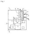
- an engine working machine 1 includes an engine 3, a working machine 4 e.g. a compressor or a dynamo, a radiator 5, a cooling fan 6 and so on incorporated in a package 2.
- a working machine 4 e.g. a compressor or a dynamo
- a radiator 5 e.g. a radiator or a cooling fan 6 and so on incorporated in a package 2.
- the engine 3 is mounted on the base of the package 2.
- the working machine 4 is connectedly attached to the output side of the engine 3 so as to be driven by the engine 3.
- An intake pipe 7 is extended upward from the engine 3.
- a noise reduction appliance (a resonator) 8 is attached to the halfway of the intake pipe 7.
- the radiator 5 is provided above the engine 3 on the opposite side to the working machine 4, and a cooling fan 6 is fit in the radiator 5.
- Partitions 9 which partition the interior space of the package 2 into a space (a leading space of the air after having passed through the radiator) E1 and a space (a storing space for the engine and working machine) E2.
- the radiator 5 and the cooling fan 6 are provided in the space E1
- the engine 3, the working machine 4 and so on are provided in the space E2.
- a radiator wind leading port 11 opens on one side face of the package 2 so as to face the radiator 5.
- heat exchange air A is led into the radiator 5 from the leading port 11, and passes through the radiator 5 while being inhaled into the cooling fan 6.
- An exhaust port 14 opens on a ceiling face of the package 2 placed above the cooling fan 6, and the air A after having passed through the radiator 5 is exhaled from the exhaust port 14.
- a gap 15 is formed between the radiator 5 and the cooling fan 6, and a ventilating port 13, through which the space E1 communicates with the space E2, is formed at the partition 9 which is placed at the gap 15.
- a ventilating port (an air leading port) 12 opens on the base of the package 2 on the side of the working machine 4.
- the cooling fan 6 inhales outside air A from the radiator wind leading port 11, and this air A is used for heat exchange of radiator 5 and is exhausted from the exhaust port 14.
- the space E1 is separated from the space E2 by the partitions 9, therefore, by the inhalation force of the cooling fan 6, the pressure in the space E1, especially in the gap 15 between the radiator 5 and the cooling fan 6, is negative.
- the space E1 communicates with the space E2 by the ventilating port 13
- the air A in the space E2 is inhaled into the space E1 in which the pressure is negative by the inhalation force of the cooling fan 6, and is exhaled through the exhaust port 14.
- outside air B is led from the air leading port 12 which opens on the base of the package 2. Then, the air B enters the space E1 through the ventilating port 13 after having passed through the working machine 4 and the engine 3 in sequence, and is exhaled from the exhaust port 14. That is, the air B, which is led into the space E2 from the air leading port 12, cools down the working machine 4 and the engine 3 in sequence as cooling wind, and is exhaled together with the above-said air A from the exhaust port 14.
- the negative pressure space E1 generated by the cooling fan 6 is provided at the downstream from the engine 3 and the working machine 4 in the flow of the external cooling wind B for the engine 3 and the working machine 4.
- the cooling wind led from the air leading port 12 securely flows into the space E1 through the ventilating port 13, thereby removing the conventional necessity of forming a lot of exhausting vents (exhausting vents 2a as shown in Fig. 2 ).
- the noise of the engine 3 or the working machine 4 in the space E2 hardly escapes outside through the air leading port 12 which opens on the base of the package 2, and the air from the air leading port 12 has a low temperature such as to efficiently cool the engine 3, the working machine 4 and so on. Consequently, there can be provided the engine working machine 1 which has little outward escape of noise and has sufficient advantages in cooling and isolation.
- the working machine 4 is placed nearer to the air leading port 12 (i.e. the upstream side of the cooling wind) than the engine 3. Therefore, the outside air B, which is led from the air leading port 12 and is exhaled from the ventilating port 13, flows so as to cool the hottest engine 3 after cooling the working machine 4. If the working machine were cooled by the air after cooling the hot engine, the cooling effect thereof would be small. However, in such a structure of the engine working machine 1, because the cool air B can touch the working machine 4 immediately, the working machine 4 can be cooled effectively. In consequence, great cooling effect of the engine 3 and the working machine 4 as a port can be obtained.
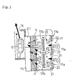
- the radiator wind leading port 11 is formed therein with a plurality of rows (in this embodiment, two rows) of soundproof walls 17a and 17b before and behind in a longitudinal direction of air leading.
- Each of the soundproof walls 17a and 17b is made of a board 22 and sound absorption material 21 stuck on an inside surface (toward the radiator 5) of the board 22.
- the soundproof walls 17a and 17b are extended (rightward and leftward in this embodiment) substantially in perpendicular to the air leading direction.
- the soundproof walls 17a in the row disposed adjacent to the outer end of the radiator wind leading port 11, and the soundproof walls 17b in the row disposed inward of the soundproof wall 17a are arranged among gaps at substantially regular intervals serving as air passages, respectively.
- the front air passages among the soundproof walls 17a are arranged alternately with the respective rear air passages among the soundproof walls 17b.
- top-and-bottom ends of the air passages of the soundproof walls 17a overlap with those of the soundproof walls 17b overlap forward and backward.
- Noise is generated when the air passes through the radiator 5.
- the sound waves therefrom (drawn as hollow arrows N in Fig. 3 ) are propagated to the outer end of the leading port 11. Firstly, these sound waves N strike the sound absorption material 21 on the inside faces of the soundproof walls 17b and absorbed thereinto.
- the remaining sound waves N which are not absorbed, pass through the air passages, and then, strike the sound absorption material 21 on the inside faces of the soundproof walls 17a and are absorbed thereinto.
- the still remaining sound waves N which are not absorbed yet, are diffracted along the outside faces of the soundproof walls 17b (the outside faces of the boards 22) and interfere with one another and with sound waves generated from the air led to the radiator 5, thereby being counteracted moreover.
- the sound caused by such counteracted sound waves escaping to the outside from the gaps among the soundproof walls 17a is not so loud as to be recognized as noise.
- the radiator wind leading port 11 of the present invention has a structure such as to reduce an escape of noise.
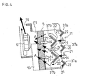
- Soundproof walls 37a and 37b shown in Fig. 4 are provided as an embodiment of the soundproof walls 17a and 17b modified in shapes for reducing a pressure loss of the air led into the radiator 5 while having the structure similar with that shown in Fig. 3 (wherein sound absorption material 21 is stuck on the inside surface of the board 22, and backward-and-forward alternate arrangement of the gaps for air passing is also adopted).
- Each of the soundproof walls 37a corresponding to the soundproof walls 17a and each of the soundproof walls 37b corresponding to the soundproof walls 17b are sectionally formed among the gaps into a substantial V-like shape which opens toward the side of the radiator 5.
- the air A which is led from the radiator wind leading port 11 in the structure shown in Fig. 3 , before passing the gaps among the soundproof walls 17a and the gaps among the soundproof walls 17b, hits on the respective soundproof walls 17a and 17b having shapes like flat boards, and is guided into each gap along the respective outside faces of the walls 17a and 17b.
- the flow of the air A is bent at an angle of about 90 degrees by hitting on such flat faces of the walls 17a and 17b to be led into each gap so that the pressure loss of intake wind for the radiator tends to be large.
- soundproof walls 37a and 37b shown in Fig. 4 are formed among the gaps into substantial V-like shapes that open toward the side of the radiator 5.
- the outside air A which hits on the soundproof walls 37a, and the air A which hits on the soundproof walls 37b after having passed through the soundproof wall 37a flows diagonally along each of the walls from the bending portions thereof to the side of the radiator 5 so as to be guided into each gap.
- the flow of the air A is not bent sharply, that is, it is smoothed so as to reduce the pressure loss for intake of the radiator.
- the soundproof walls 37a are arranged alternately with the respective soundproof walls 37b while the ends of the soundproof walls 37a overlap with those of the soundproof wall 37b, thereby exerting the noise reducing effect equal to that by the above-said soundproof walls 17a and 17b.
- Three or more rows of soundproof walls may be formed in the radiator wind leading port 11.
- all to be required is that any two adjacent front and rear rows of soundproof walls are structured as the above-mentioned structure of the soundproof walls 17a and 17b or the soundproof walls 37a and 37b, that is, backward-and-forward alternate arrangement of the gaps for air passing.
- the gaps for air passing may be formed as slits extended to the port width or the port height, or may be formed as a plurality of ports.
- any shape or form is available, for example, a slot or a honeycomb. In a word, it is all right only if the forward and backward gaps are arranged alternately so that the air, which has passed through the leading gap to the side of the radiator 5, hits on the backward soundproof wall.
- the gaps may partly overlap.
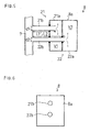
- a noise reduction appliance (a dual resonator) 8 shown in Figs. 5 and 6 is integrally formed with a first resonator 21 and a second resonator 22.
- the first resonator 21 comprises a resonance pipe 21b which extends from the intake pipe 7, and a resonance room 21a which is formed at the apex portion of the resonance pipe 21b.
- the second resonator 22 comprises a resonance pipe 22b which extends from the intake pipe 7 and pierces the resonance room 21a of the first resonator 21, and a resonance room 22a which is formed at the apex portion of the resonance pipe 22b.
- the resonance room 21a and the resonance room 22a are formed into a unified box constituting a resonance room section 8a of the resonator 8.
- the resonator 8 is constructed such that the two resonance pipes 21b and 22b are projected from the resonance room section 8a constituted by the unified resonance rooms 21a and 22a.
- the resonator 8 is joined to the intake pipe 7 by connecting the resonance pipes 21b and 22b to the intake pipe 7.
- the speed of sound is designated as c
- the diameter of the resonance pipe is designated as d
- the length of the resonance pipe is designated as L
- the volume of the resonance room is designated as V.
- the absorbable frequency band depends on the diameter of the resonance pipe d, the length of the resonance pipe L, and the volume of the resonance room V.
- the absorbable frequency band depends on the diameter of the resonance pipe d1, the length of the resonance pipe L1, and the volume of the resonance room V1. These characteristics are set so as to enable the absorption of the desired frequency band.
- the absorbable frequency band depends on the diameter of the resonance pipe d2, the length of the resonance pipe L2, and the volume of the resonance room V2. These characteristics are set so as to enable the absorption of the desired frequency band which differs from the frequency band set in the first resonator 21.
- the resonator 8 comprises, for example, two resonators, the first resonator 21 and the second resonator 22, which are unified with each other and set so as to have different resonance frequencies f, thereby absorbing noise of two different frequency bands.
- Fig. 7 shows a spectrum of intake noise, which graphs the relationship between the frequency and the engine intake noise.
- an intake noise spectrum 25 designates the level of the engine intake noise at every frequency in the case that the resonator 8 is not attached to the intake pipe 7.
- This intake noise spectrum 25 shows the higher levels of intake noise at two frequency bands f1 and f2.
- the absorbable frequency band of the first resonator 21 is corresponded to the frequency band f1
- the absorbable frequency band of the second resonator 22 is corresponded to the frequency band f2, thereby absorbing the intake noise of both frequency bands f1 and f2 and reducing the intake noise level.
- the resonator 8 comprising the first and second resonators 21 and 22 is attached to the intake pipe 7, the intake noise levels at a plurality of frequency bands can be reduced so that the engine intake noise can be reduced very well.
- the surface area of the resonance room section 8a can be smaller than the total surface area in the case that the two resonance rooms 21a and 22a are formed separately from each other, thereby reducing radiant noise from the resonator 8 the better.
- the engine working machine 1 can be miniaturized and can be formed at low cost.
- the rigidity which supports the resonance room section 8a can be improved so as to reduce the radiant noise generated from the resonator 8 by vibration of the resonance room section 8a and so on, and the fears of cracks in the resonance room section 8a and the resonance pipes 21b and 22b can be diminished so as to improve the reliabilities thereof.
- the intake noise spectrum shows three frequency bands or more where the intake noise levels are high, so many resonators may be unified.
- This resonator 38 comprises a first resonator 41 and a second resonator 42 unified with each other.
- the first resonator 41 comprises a resonance pipe 41b which extends from the intake pipe 7, and a resonance room 41a which is formed at the apex portion of the resonance pipe 41b.
- the second resonator 42 comprises a resonance pipe 42b which extends from the intake pipe 7 and pierces the resonance pipe 41b and the resonance room 41a of the first resonator 41, and a resonance room 42a which is formed at the apex portion of the resonance pipe 42b.
- the resonance rooms 41a and 42a are unified in a box-like shape so as to constitute a resonance room section 38a of the resonator 38.
- the resonance pipes 41b and the resonance pipe 42b, which pierces the resonance pipe 41b, are formed into a double pipe.
- the resonator 38 is constructed such that the two resonance pipes 41b and 42b formed as a double pipe are projected from the resonance room section 38a as the unified resonance rooms 41a and 42a.
- the resonator 38 is joined to the intake pipe 7 by connecting the resonance pipes 41b and 42b to the intake pipe 7.
- the absorbable frequency band of the first resonator 41 depends on the diameter of the resonance pipe d3, the length of the resonance pipe L3, and the volume of the resonance room V3. These characteristics are set so as to enable the absorption of the desired frequency band.
- the absorbable frequency band of the second resonator 42 depends on the diameter of the resonance pipe d4, the length of the resonance pipe L4, and the volume of the resonance room V4. These characteristics are set so as to enable the absorption of the desired frequency band which differs from the frequency band set in the first resonator 41.
- the resonator 38 comprises two unified resonators, the first and second resonators 41 and 42, which have respective different resonance frequencies f so as to absorb noise of two different frequency bands, thereby exerting an excellent effect of reducing noise similarly with the above-mentioned resonator 8.
- This resonator 8 can have advantages in reduction of radiant noise from the resonator 38 because of the unified resonance rooms 41a and 41b, and in miniaturization and cost-saving of the engine working machine 1, similarly with the former resonator 8.
- a resonator comprising three unified resonance rooms or more and a triple-or-more-bonded pipe may be formed.
- the package storing type engine working machine according to the present invention which generates little noise due to the above-mentioned structure, is useful for various purposes such as electric power generation, pump-driving or compressor-driving at a place where silence is required.
Landscapes
- Engineering & Computer Science (AREA)
- Physics & Mathematics (AREA)
- Acoustics & Sound (AREA)
- Chemical & Material Sciences (AREA)
- Combustion & Propulsion (AREA)
- Mechanical Engineering (AREA)
- General Engineering & Computer Science (AREA)
- Cooling, Air Intake And Gas Exhaust, And Fuel Tank Arrangements In Propulsion Units (AREA)
- Exhaust Silencers (AREA)
- Soundproofing, Sound Blocking, And Sound Damping (AREA)
Description
- The present invention relates to a low noise package storing type engine working machine which includes an engine and a working machine contained in a package, wherein escape of noise e.g. the engine noise (especially intake noise) or sound of air passing through a radiator is reduced.
- As shown in
Fig. 2 , an engine working machine 1', wherein a working machine e.g. a compressor, a dynamo or so on is connectedly attached to a water-cooling type engine 3, and these are contained in apackage 2, is known. Air after exchanging heat at aradiator 5 is led into thepackage 2, and used for externally cooling theengine 3 and the workingmachine 4, and exhausted through ventilating vents (exhausting vents) 2a, 2a... which are formed at side and bottom surfaces of thepackage 2. - In these circumstances, because noise is generated when air for
radiator 5 is led into thepackage 2, sound absorption materials is placed at anair leading port 11 for heat exchanging of theradiator 5. However, because the air A' is led from theair leading port 11 to theradiator 5 almost straightly, noise generated in theair leading port 11 escapes to outside as it is, in consequence, noise reducing effect is small. - Further, external cooling wind B' of the engine working machine 1' is generated by a
cooling fan 6 leading heat exchange air A' toradiator 5. In other words, thecooling fan 6 which feeds cooling wind is disposed in the upstream of theengine 3 and theworking machine 4, and there is no special member to guide wind in the downstream from theengine 3 and theworking machine 4. Therefore, a lot ofexhausting vents 2a are formed at side and bottom surfaces of thepackage 2 to generate smooth flow of external cooling wind B' for theengine 3 and theworking machine 4. Consequently, there is a problem that noise generated from theengine 3 and so on escapes to outside through manyexhausting vents 2a with cooling wind B' which has circulated in thepackage 2. Moreover, the air A' used for the heat exchanging of theradiator 5 has been warmed at the time of passing through theradiator 5. Thus, the air A', if being used as the external cooling wind B' for theengine 3 and theworking machine 4, has little cooling effect. - Now, there is engine intake noise as one of engine noise elements. Conventionally, a resonator 8' that reduces this noise with resonance is attached to a halfway of an intake pipe of an engine.
- But, noise reduction effect of this
resonator 8 is sufficient only for a specific frequency band. Conventionally, there can be provided only one resonator in the narrow space of the package, which can insufficiently reduce the noise in the case when there are more than one peak frequency band in the intake noise. Attaching more than one resonator to the intake pipe causes enlargement of the engine working machine. Also, it seems that the resonators more than one can reduce noise of multi frequency bands and improve in total noise reducing effect, however, in fact, each resonator makes itself vibrate by resonation with noise so as to generate radiant noise. Far from reducing the noise, such an arrangement of more than one resonator results in that the radiant noise sources are increased so as to diminish the noise reduction effect. - Document
EP 0 799 979 shows a similar package. - An object of the invention is to provide a low noise package storing type engine working machine.
- Therefore, according to the present invention, first, a low noise engine working machine formed by storing a radiator and a cooling fan for leading heat exchange air for the radiator in a package together with an engine and a working machine is constructed such that a storing space for the engine and the working machine excluding a ventilating port communicating to a space between the radiator and the cooling fan is shielded from an air leading space to which air is led after being passed through the radiator by the cooling fan, and a cooling air leading port for externally cooling the engine and the working machine is formed in a part of the package so that outside air led from the cooling air leading port passes the storing space for the engine and the working machine and is exhausted from the ventilating port to the air leading space to which air led after having passed through the radiator.
- Next, as for an air leading port for leading air to the radiator, according to the present invention, a plurality of forward-and-backward rows of soundproof walls are formed parallel in a direction of flow of air therein, and air passages are formed in each row of the soundproof wall so as to be placed alternately with air passages formed in the forward or backward adjacent row of soundproof wall in the direction perpendicular to the flow of air. In this regard, a sectional shape of the soundproof wall formed between any adjacent two of said air passages in each row of the soundproof wall may be formed in a substantial V-like shape which opens toward the side of the radiator.
- Further, as for the reduction of engine intake noise, according to the present invention, the engine intake noise reduction apparatus comprising a plurality of unified resonators is attached to an intake pipe of an engine in an engine working machine formed by storing a radiator and a cooling fan for leading heat exchange air for the radiator in a package together with the engine and a working machine. In this connection, a resonation pipe of each resonator in said noise reduction appliance may be formed as a multiplexed pipe.
- Said and other features and advantages of the invention will be apparent more fully from the following description and the accompanying drawing.
-
-
Fig. 1 is a schematic interior side view showing a low noise package storing typeengine working machine 1 of the present invention; -
Fig. 2 is a schematic interior side view showing a conventional low noise package storing type engine working machine 1'; -
Fig. 3 is a schematic sectional side view showing an embodiment of noise reducing construction that is provided in a cooling wind leading port of a radiator. -
Fig. 4 is a schematic sectional side view showing another embodiment of the same; -
Fig. 5 is a sectional side view showing an embodiment of means to reduce engine intake noise according to the present invention; -
Fig. 6 is an elevation view of the same; -
Fig. 7 is a chart of spectral characteristics of intake noise, which graphs the relationship between the frequency and the engine intake noise, showing the noise reduction effect due to the means of the present invention for arresting the engine intake noise; -
Fig. 8 is a side view showing another embodiment of the same; and -
Fig. 9 is an elevation view of the same. - This invention will be described in further detail with reference to the accompanying drawings.
- As shown in
Figs. 1 and3 , anengine working machine 1 according to the present invention includes anengine 3, aworking machine 4 e.g. a compressor or a dynamo, aradiator 5, acooling fan 6 and so on incorporated in apackage 2. - The
engine 3 is mounted on the base of thepackage 2. Theworking machine 4 is connectedly attached to the output side of theengine 3 so as to be driven by theengine 3. - An
intake pipe 7 is extended upward from theengine 3. In order to reduce intake air noise which is generated when inhaling air fromintake pipe 7, a noise reduction appliance (a resonator) 8 is attached to the halfway of theintake pipe 7. - The
radiator 5 is provided above theengine 3 on the opposite side to theworking machine 4, and acooling fan 6 is fit in theradiator 5. -
Partitions 9, which partition the interior space of thepackage 2 into a space (a leading space of the air after having passed through the radiator) E1 and a space (a storing space for the engine and working machine) E2. Theradiator 5 and thecooling fan 6 are provided in the space E1, and theengine 3, theworking machine 4 and so on are provided in the space E2. - A radiator
wind leading port 11 opens on one side face of thepackage 2 so as to face theradiator 5. By the rotation of thecooling fan 6, which is placed on the opposite side to the radiatorwind leading port 11 with theradiator 5 between, heat exchange air A is led into theradiator 5 from the leadingport 11, and passes through theradiator 5 while being inhaled into thecooling fan 6. Anexhaust port 14 opens on a ceiling face of thepackage 2 placed above thecooling fan 6, and the air A after having passed through theradiator 5 is exhaled from theexhaust port 14. - A
gap 15 is formed between theradiator 5 and thecooling fan 6, and a ventilating port 13, through which the space E1 communicates with the space E2, is formed at thepartition 9 which is placed at thegap 15. - Moreover, a ventilating port (an air leading port) 12 opens on the base of the
package 2 on the side of theworking machine 4. - The
cooling fan 6 inhales outside air A from the radiatorwind leading port 11, and this air A is used for heat exchange ofradiator 5 and is exhausted from theexhaust port 14. The space E1 is separated from the space E2 by thepartitions 9, therefore, by the inhalation force of thecooling fan 6, the pressure in the space E1, especially in thegap 15 between theradiator 5 and thecooling fan 6, is negative. - Because the space E1 communicates with the space E2 by the ventilating port 13, the air A in the space E2 is inhaled into the space E1 in which the pressure is negative by the inhalation force of the
cooling fan 6, and is exhaled through theexhaust port 14. - Therefore, in the space E2, outside air B is led from the
air leading port 12 which opens on the base of thepackage 2. Then, the air B enters the space E1 through the ventilating port 13 after having passed through theworking machine 4 and theengine 3 in sequence, and is exhaled from theexhaust port 14. That is, the air B, which is led into the space E2 from theair leading port 12, cools down theworking machine 4 and theengine 3 in sequence as cooling wind, and is exhaled together with the above-said air A from theexhaust port 14. - Conventionally, because heat exchange air of a radiator is untouched and used for external cooling wind of an engine and a working machine, there is a problem that the circulation of the heat exchange air is poor (therefore, the necessity of forming a lot of exhausting hall results in generating factors of noise.), and cooling effect is low. In the present
engine working machine 1, in the above-mentioned manner, the heat exchange air A of theradiator 5 and the external cooling air B is generated by the inhalation force of thecooling fan 6. The former air A is separated from the latter cooling wind B so as not to enter the space E2 for placing the engine and the working machine. Additionally, the negative pressure space E1 generated by thecooling fan 6 is provided at the downstream from theengine 3 and theworking machine 4 in the flow of the external cooling wind B for theengine 3 and theworking machine 4. The cooling wind led from theair leading port 12 securely flows into the space E1 through the ventilating port 13, thereby removing the conventional necessity of forming a lot of exhausting vents (exhausting vents 2a as shown inFig. 2 ). Moreover, the noise of theengine 3 or the workingmachine 4 in the space E2 hardly escapes outside through theair leading port 12 which opens on the base of thepackage 2, and the air from theair leading port 12 has a low temperature such as to efficiently cool theengine 3, the workingmachine 4 and so on. Consequently, there can be provided theengine working machine 1 which has little outward escape of noise and has sufficient advantages in cooling and isolation. - In addition, the working
machine 4 is placed nearer to the air leading port 12 (i.e. the upstream side of the cooling wind) than theengine 3. Therefore, the outside air B, which is led from theair leading port 12 and is exhaled from the ventilating port 13, flows so as to cool thehottest engine 3 after cooling the workingmachine 4. If the working machine were cooled by the air after cooling the hot engine, the cooling effect thereof would be small. However, in such a structure of theengine working machine 1, because the cool air B can touch the workingmachine 4 immediately, the workingmachine 4 can be cooled effectively. In consequence, great cooling effect of theengine 3 and the workingmachine 4 as a port can be obtained. - Next, a noise reducing structure of the port (a radiator wind leading port) 11 for leading heat exchange air to the radiator will be described. As shown in
Fig. 3 , the radiatorwind leading port 11 is formed therein with a plurality of rows (in this embodiment, two rows) ofsoundproof walls soundproof walls board 22 andsound absorption material 21 stuck on an inside surface (toward the radiator 5) of theboard 22. Thesoundproof walls - The
soundproof walls 17a in the row disposed adjacent to the outer end of the radiatorwind leading port 11, and thesoundproof walls 17b in the row disposed inward of thesoundproof wall 17a are arranged among gaps at substantially regular intervals serving as air passages, respectively. The front air passages among thesoundproof walls 17a are arranged alternately with the respective rear air passages among thesoundproof walls 17b. However, top-and-bottom ends of the air passages of thesoundproof walls 17a overlap with those of thesoundproof walls 17b overlap forward and backward. - In such a radiator
wind leading port 11 air is led into theradiator 5 while passing through the air passages provided among thesoundproof walls Fig. 3 . - Noise is generated when the air passes through the
radiator 5. The sound waves therefrom (drawn as hollow arrows N inFig. 3 ) are propagated to the outer end of the leadingport 11. Firstly, these sound waves N strike thesound absorption material 21 on the inside faces of thesoundproof walls 17b and absorbed thereinto. The remaining sound waves N, which are not absorbed, pass through the air passages, and then, strike thesound absorption material 21 on the inside faces of thesoundproof walls 17a and are absorbed thereinto. The still remaining sound waves N, which are not absorbed yet, are diffracted along the outside faces of thesoundproof walls 17b (the outside faces of the boards 22) and interfere with one another and with sound waves generated from the air led to theradiator 5, thereby being counteracted moreover. The sound caused by such counteracted sound waves escaping to the outside from the gaps among thesoundproof walls 17a is not so loud as to be recognized as noise. In this way, the radiatorwind leading port 11 of the present invention has a structure such as to reduce an escape of noise. -
Soundproof walls Fig. 4 are provided as an embodiment of thesoundproof walls radiator 5 while having the structure similar with that shown inFig. 3 (whereinsound absorption material 21 is stuck on the inside surface of theboard 22, and backward-and-forward alternate arrangement of the gaps for air passing is also adopted). Each of thesoundproof walls 37a corresponding to thesoundproof walls 17a and each of thesoundproof walls 37b corresponding to thesoundproof walls 17b are sectionally formed among the gaps into a substantial V-like shape which opens toward the side of theradiator 5. - The air A, which is led from the radiator
wind leading port 11 in the structure shown inFig. 3 , before passing the gaps among thesoundproof walls 17a and the gaps among thesoundproof walls 17b, hits on the respectivesoundproof walls walls walls - Therefore,
soundproof walls Fig. 4 are formed among the gaps into substantial V-like shapes that open toward the side of theradiator 5. The outside air A which hits on thesoundproof walls 37a, and the air A which hits on thesoundproof walls 37b after having passed through thesoundproof wall 37a, flows diagonally along each of the walls from the bending portions thereof to the side of theradiator 5 so as to be guided into each gap. Thus, the flow of the air A is not bent sharply, that is, it is smoothed so as to reduce the pressure loss for intake of the radiator. - Moreover, between the two rows of the
soundproof walls soundproof walls 37a are arranged alternately with the respectivesoundproof walls 37b while the ends of thesoundproof walls 37a overlap with those of thesoundproof wall 37b, thereby exerting the noise reducing effect equal to that by the above-saidsoundproof walls - Three or more rows of soundproof walls may be formed in the radiator
wind leading port 11. In this case, all to be required is that any two adjacent front and rear rows of soundproof walls are structured as the above-mentioned structure of thesoundproof walls soundproof walls - The gaps for air passing may be formed as slits extended to the port width or the port height, or may be formed as a plurality of ports. In case that the gaps are formed as ports, any shape or form is available, for example, a slot or a honeycomb. In a word, it is all right only if the forward and backward gaps are arranged alternately so that the air, which has passed through the leading gap to the side of the
radiator 5, hits on the backward soundproof wall. The gaps may partly overlap. - Next, a noise reduction appliance of the present invention will be described with reference to
Figs. 5-9 . A noise reduction appliance (a dual resonator) 8 shown inFigs. 5 and 6 is integrally formed with afirst resonator 21 and asecond resonator 22. - The
first resonator 21 comprises aresonance pipe 21b which extends from theintake pipe 7, and aresonance room 21a which is formed at the apex portion of theresonance pipe 21b. Thesecond resonator 22 comprises aresonance pipe 22b which extends from theintake pipe 7 and pierces theresonance room 21a of thefirst resonator 21, and aresonance room 22a which is formed at the apex portion of theresonance pipe 22b. Theresonance room 21a and theresonance room 22a are formed into a unified box constituting aresonance room section 8a of theresonator 8. - That is, the
resonator 8 is constructed such that the tworesonance pipes resonance room section 8a constituted by theunified resonance rooms resonator 8 is joined to theintake pipe 7 by connecting theresonance pipes intake pipe 7. - The
resonator 8 absorbs only noise of a specific frequency band by internal resonance, and the frequency band that can be absorbed is formularized as the resonance frequency f in the following equation (1):
- In the equation (1), the speed of sound is designated as c, the diameter of the resonance pipe is designated as d, the length of the resonance pipe is designated as L, and the volume of the resonance room is designated as V.
- The absorbable frequency band depends on the diameter of the resonance pipe d, the length of the resonance pipe L, and the volume of the resonance room V.
- In the
first resonator 21 of the present embodiment, the absorbable frequency band depends on the diameter of the resonance pipe d1, the length of the resonance pipe L1, and the volume of the resonance room V1. These characteristics are set so as to enable the absorption of the desired frequency band. - In the
second resonator 22, similarly, the absorbable frequency band depends on the diameter of the resonance pipe d2, the length of the resonance pipe L2, and the volume of the resonance room V2. These characteristics are set so as to enable the absorption of the desired frequency band which differs from the frequency band set in thefirst resonator 21. - Thus, the
resonator 8 comprises, for example, two resonators, thefirst resonator 21 and thesecond resonator 22, which are unified with each other and set so as to have different resonance frequencies f, thereby absorbing noise of two different frequency bands. -
Fig. 7 shows a spectrum of intake noise, which graphs the relationship between the frequency and the engine intake noise. In this graph, anintake noise spectrum 25 designates the level of the engine intake noise at every frequency in the case that theresonator 8 is not attached to theintake pipe 7. Thisintake noise spectrum 25 shows the higher levels of intake noise at two frequency bands f1 and f2. - Therefore, in the
resonator 8, for example, the absorbable frequency band of thefirst resonator 21 is corresponded to the frequency band f1, and the absorbable frequency band of thesecond resonator 22 is corresponded to the frequency band f2, thereby absorbing the intake noise of both frequency bands f1 and f2 and reducing the intake noise level. - In the case where the so-called
dual resonator 8, whose absorbable frequency bands are set to the frequency bands f1 and f2, is attached to theintake pipe 7, the intake noise levels at the frequency bands f1 and f2 are vastly reduced as shown by anintake noise spectrum 26 inFig. 7 . - Thus, since the
resonator 8 comprising the first andsecond resonators intake pipe 7, the intake noise levels at a plurality of frequency bands can be reduced so that the engine intake noise can be reduced very well. - Furthermore, since the
resonance rooms second resonators resonance room section 8a can be smaller than the total surface area in the case that the tworesonance rooms resonator 8 the better. In addition, since the space occupied by theresonator 8 and the number of components thereof can be reduced, theengine working machine 1 can be miniaturized and can be formed at low cost. - Besides, since the
resonator 8 is attached to theintake pipe 7 by the tworesonance pipes resonance room section 8a can be improved so as to reduce the radiant noise generated from theresonator 8 by vibration of theresonance room section 8a and so on, and the fears of cracks in theresonance room section 8a and theresonance pipes - In the case where the intake noise spectrum shows three frequency bands or more where the intake noise levels are high, so many resonators may be unified.
- Next, a
resonator 38 shown inFigs. 8 and 9 as another embodiment of theresonator 8 will be described. Thisresonator 38 comprises afirst resonator 41 and asecond resonator 42 unified with each other. - The
first resonator 41 comprises aresonance pipe 41b which extends from theintake pipe 7, and aresonance room 41a which is formed at the apex portion of theresonance pipe 41b. Thesecond resonator 42 comprises aresonance pipe 42b which extends from theintake pipe 7 and pierces theresonance pipe 41b and theresonance room 41a of thefirst resonator 41, and aresonance room 42a which is formed at the apex portion of theresonance pipe 42b. Theresonance rooms resonance room section 38a of theresonator 38. - The
resonance pipes 41b and theresonance pipe 42b, which pierces theresonance pipe 41b, are formed into a double pipe. - That is to say, the
resonator 38 is constructed such that the tworesonance pipes resonance room section 38a as theunified resonance rooms resonator 38 is joined to theintake pipe 7 by connecting theresonance pipes intake pipe 7. - The absorbable frequency band of the
first resonator 41 depends on the diameter of the resonance pipe d3, the length of the resonance pipe L3, and the volume of the resonance room V3. These characteristics are set so as to enable the absorption of the desired frequency band. - Similarly, the absorbable frequency band of the
second resonator 42 depends on the diameter of the resonance pipe d4, the length of the resonance pipe L4, and the volume of the resonance room V4. These characteristics are set so as to enable the absorption of the desired frequency band which differs from the frequency band set in thefirst resonator 41. - Thus, for example, the
resonator 38 comprises two unified resonators, the first andsecond resonators resonator 8. - This
resonator 8 can have advantages in reduction of radiant noise from theresonator 38 because of theunified resonance rooms engine working machine 1, similarly with theformer resonator 8. - According to the manner like that in the
resonator 38, a resonator comprising three unified resonance rooms or more and a triple-or-more-bonded pipe may be formed. - The package storing type engine working machine according to the present invention, which generates little noise due to the above-mentioned structure, is useful for various purposes such as electric power generation, pump-driving or compressor-driving at a place where silence is required.
Claims (3)
- A packaged low noise engine working machine (1) comprising
a package (2) defining a storing space (E2) for an engine and a working machine and the package further defining an air leading space (E1) to which air is led after being passed through a radiator (5) by a cooling fan (6), said air leading space being shielded from said storing space (E2);
said engine (3) and said working machine (4) driven by said engine (3) disposed in said storing space (E2);
said cooling fan (6) being disposed in said air leading space (E1) such that the cooling fan (6) in operation leads air having passed through the radiator (5) to the air leading space (E1) and such that a gap (15) is provided between said radiator (5) and said cooling fan (6);
a ventilating port (13) opened to the gap (15) such that the storing space (E2) communicates with the air leading space (E1) by the ventilating port (13); and
an air leading port (12) opened to the storing space (E2) on a side of the working machine (4) such that, in operation, outside air is led into the storing space (E2) from the air leading port (12), passes the working machine (4) and the engine (3) in sequence so as to cool the working machine (4) prior to the engine (3), and is exhausted from the storing space (E2) to the air leading space (E1) through the ventilating port (13). - The packaged low noise engine working machine according to claim 1, further comprising
an air leading port (11) for leading air to the radiator (5), wherein a plurality of forward-and-backward rows of soundproof walls (17a,17b;37a,37b) are formed in the air leading port (11) parallel in a direction of flow of air, and air passages are formed in each row of the soundproof walls (17a,17b;37a,37b) so as to be placed alternately with air passages formed in the forward or backward adjacent row of soundproof walls (17a,17b;37a,37b) in the direction perpendicular to the flow of air. - The packaged low noise engine working machine according to claim 2, wherein a sectional shape of the soundproof wall (37a,37b) formed between any adjacent two of said air passages in each row of the soundproof walls (37a,37b) is formed in a substantial V-like shape which opens toward the side of the radiator (5).
Applications Claiming Priority (5)
| Application Number | Priority Date | Filing Date | Title |
|---|---|---|---|
| JP28433298 | 1998-10-06 | ||
| JP10284332A JP2000110679A (en) | 1998-10-06 | 1998-10-06 | Engine intake noise reducing device in engine work machine |
| JP28433198A JP3984732B2 (en) | 1998-10-06 | 1998-10-06 | Driving noise reduction device for engine working machine package |
| JP28433198 | 1998-10-06 | ||
| PCT/JP1999/005243 WO2000020737A1 (en) | 1998-10-06 | 1999-09-24 | Low noise package storing type engine working machine |
Publications (4)
| Publication Number | Publication Date |
|---|---|
| EP1120558A1 EP1120558A1 (en) | 2001-08-01 |
| EP1120558A8 EP1120558A8 (en) | 2001-10-17 |
| EP1120558A4 EP1120558A4 (en) | 2006-05-24 |
| EP1120558B1 true EP1120558B1 (en) | 2009-11-25 |
Family
ID=26555427
Family Applications (1)
| Application Number | Title | Priority Date | Filing Date |
|---|---|---|---|
| EP99944831A Expired - Lifetime EP1120558B1 (en) | 1998-10-06 | 1999-09-24 | Low noise package storing type engine working machine |
Country Status (7)
| Country | Link |
|---|---|
| US (1) | US6463905B1 (en) |
| EP (1) | EP1120558B1 (en) |
| AU (1) | AU753503C (en) |
| CA (1) | CA2345666C (en) |
| DE (1) | DE69941722D1 (en) |
| ES (1) | ES2334728T3 (en) |
| WO (1) | WO2000020737A1 (en) |
Families Citing this family (6)
| Publication number | Priority date | Publication date | Assignee | Title |
|---|---|---|---|---|
| DE102005058251B4 (en) * | 2004-12-28 | 2014-04-24 | Johann Borgers GmbH | Sound absorber for motor vehicle engines |
| US8672089B2 (en) | 2008-11-27 | 2014-03-18 | Caterpillar (Ni) Limited | Baffle arrangement for a genset enclosure |
| JP5637360B2 (en) * | 2010-06-15 | 2014-12-10 | アイシン精機株式会社 | Outdoor power generator |
| CN103075605B (en) * | 2013-01-10 | 2015-04-29 | 重庆大学 | Double-cavity resonant type muffler |
| SE540084C2 (en) * | 2016-07-04 | 2018-03-20 | Scania Cv Ab | Ventilation device for venting a space, in particular an engine room of a vehicle |
| CN114523841B (en) * | 2022-03-30 | 2025-07-01 | 江苏徐工工程机械研究院有限公司 | Power cabin and engineering machinery having the same |
Family Cites Families (12)
| Publication number | Priority date | Publication date | Assignee | Title |
|---|---|---|---|---|
| US1804334A (en) * | 1928-08-28 | 1931-05-05 | Charles O Guernsey | Ventilating system |
| US2720935A (en) * | 1950-08-30 | 1955-10-18 | Jarvis C Marble | Silencing of sound |
| DE2704697C3 (en) * | 1976-02-25 | 1986-08-21 | Kabushiki Kaisha Komatsu Seisakusho, Tokio/Tokyo | Generator set |
| JPS5393509A (en) | 1977-01-24 | 1978-08-16 | Hitachi Ltd | Sound proof wail |
| US4503931A (en) * | 1982-05-12 | 1985-03-12 | Kabushiki Kaisha Komatsu Seisakusho | Noise suppressing, air cooled enclosure for an engine |
| JPS6296612A (en) * | 1985-10-22 | 1987-05-06 | Tokyo Yogyo Co Ltd | Production of refractories for blowing gas |
| JPS63129137U (en) | 1987-02-13 | 1988-08-24 | ||
| JPS643035U (en) | 1987-06-25 | 1989-01-10 | ||
| JPH0566225U (en) * | 1992-02-17 | 1993-09-03 | ヤンマーディーゼル株式会社 | Soundproofing system for water-cooled engine |
| JPH0921364A (en) | 1995-07-05 | 1997-01-21 | Toyota Auto Body Co Ltd | Resonator structure for vehicle |
| JPH09112268A (en) * | 1995-10-19 | 1997-04-28 | Hitachi Constr Mach Co Ltd | Engine cooling equipment and construction machinery |
| JP3694087B2 (en) | 1996-03-19 | 2005-09-14 | 新キャタピラー三菱株式会社 | Engine room of construction machinery |
-
1999
- 1999-09-24 WO PCT/JP1999/005243 patent/WO2000020737A1/en not_active Ceased
- 1999-09-24 CA CA002345666A patent/CA2345666C/en not_active Expired - Fee Related
- 1999-09-24 DE DE69941722T patent/DE69941722D1/en not_active Expired - Lifetime
- 1999-09-24 AU AU57603/99A patent/AU753503C/en not_active Ceased
- 1999-09-24 EP EP99944831A patent/EP1120558B1/en not_active Expired - Lifetime
- 1999-09-24 ES ES99944831T patent/ES2334728T3/en not_active Expired - Lifetime
- 1999-09-24 US US09/806,867 patent/US6463905B1/en not_active Expired - Lifetime
Also Published As
| Publication number | Publication date |
|---|---|
| EP1120558A4 (en) | 2006-05-24 |
| US6463905B1 (en) | 2002-10-15 |
| CA2345666A1 (en) | 2000-04-13 |
| CA2345666C (en) | 2005-02-01 |
| DE69941722D1 (en) | 2010-01-07 |
| AU753503B2 (en) | 2002-10-17 |
| EP1120558A1 (en) | 2001-08-01 |
| AU5760399A (en) | 2000-04-26 |
| WO2000020737A1 (en) | 2000-04-13 |
| ES2334728T3 (en) | 2010-03-15 |
| EP1120558A8 (en) | 2001-10-17 |
| AU753503C (en) | 2003-09-11 |
Similar Documents
| Publication | Publication Date | Title |
|---|---|---|
| JP3866779B2 (en) | Blower soundproofing device | |
| CN109312731B (en) | Encapsulated compressor | |
| JP3728144B2 (en) | Soundproof engine driven work machine | |
| CA2345666C (en) | Low noise package storing type engine working machine | |
| JPH1061754A (en) | Air-cooled gear transmission | |
| JP6820755B2 (en) | Blower | |
| JP2009174490A (en) | Casing for compressor | |
| CN111041796B (en) | Drying air duct noise reduction structure, heat pump washing and drying integrated machine and dryer | |
| JP2837814B2 (en) | Vacuum pump silencer | |
| JP4729870B2 (en) | Construction machinery | |
| JP2013238187A (en) | Noise reducing ventilation device | |
| JP3957366B2 (en) | Storage structure for engine-driven work machines | |
| CN114704480B (en) | Multi-wing centrifugal fan based on multiple noise reduction and noise reduction method thereof | |
| JP3984732B2 (en) | Driving noise reduction device for engine working machine package | |
| CN219778516U (en) | Noise reduction structures and new energy equipment | |
| JP3006506U (en) | Engine intake silencer | |
| CN221879815U (en) | Noise reduction and silencing module and heat dissipation device | |
| WO2020262190A1 (en) | Package-type compressor | |
| CN219222957U (en) | refrigerator | |
| CN222545698U (en) | Noise reduction device and low-noise heat dissipation equipment | |
| KR102912139B1 (en) | Resonance-type noise reduction structure of folded-type | |
| CN219199594U (en) | refrigerator | |
| JP5686544B2 (en) | Package type compressor | |
| JP4631038B2 (en) | Package type compressor | |
| JP3956018B2 (en) | Low noise blower |
Legal Events
| Date | Code | Title | Description |
|---|---|---|---|
| PUAI | Public reference made under article 153(3) epc to a published international application that has entered the european phase |
Free format text: ORIGINAL CODE: 0009012 |
|
| 17P | Request for examination filed |
Effective date: 20010330 |
|
| AK | Designated contracting states |
Kind code of ref document: A1 Designated state(s): AT BE CH CY DE DK ES FI FR GB GR IE IT LI LU MC NL PT SE |
|
| RBV | Designated contracting states (corrected) |
Designated state(s): DE ES FR GB IT SE |
|
| A4 | Supplementary search report drawn up and despatched |
Effective date: 20060407 |
|
| RAP1 | Party data changed (applicant data changed or rights of an application transferred) |
Owner name: YANMAR CO., LTD. |
|
| 17Q | First examination report despatched |
Effective date: 20070322 |
|
| GRAP | Despatch of communication of intention to grant a patent |
Free format text: ORIGINAL CODE: EPIDOSNIGR1 |
|
| GRAS | Grant fee paid |
Free format text: ORIGINAL CODE: EPIDOSNIGR3 |
|
| GRAA | (expected) grant |
Free format text: ORIGINAL CODE: 0009210 |
|
| AK | Designated contracting states |
Kind code of ref document: B1 Designated state(s): DE ES FR GB IT SE |
|
| REG | Reference to a national code |
Ref country code: GB Ref legal event code: FG4D |
|
| REF | Corresponds to: |
Ref document number: 69941722 Country of ref document: DE Date of ref document: 20100107 Kind code of ref document: P |
|
| REG | Reference to a national code |
Ref country code: ES Ref legal event code: FG2A Ref document number: 2334728 Country of ref document: ES Kind code of ref document: T3 |
|
| REG | Reference to a national code |
Ref country code: SE Ref legal event code: TRGR |
|
| PLBE | No opposition filed within time limit |
Free format text: ORIGINAL CODE: 0009261 |
|
| STAA | Information on the status of an ep patent application or granted ep patent |
Free format text: STATUS: NO OPPOSITION FILED WITHIN TIME LIMIT |
|
| 26N | No opposition filed |
Effective date: 20100826 |
|
| REG | Reference to a national code |
Ref country code: FR Ref legal event code: PLFP Year of fee payment: 18 |
|
| PGFP | Annual fee paid to national office [announced via postgrant information from national office to epo] |
Ref country code: IT Payment date: 20160921 Year of fee payment: 18 Ref country code: DE Payment date: 20160920 Year of fee payment: 18 Ref country code: GB Payment date: 20160921 Year of fee payment: 18 |
|
| PGFP | Annual fee paid to national office [announced via postgrant information from national office to epo] |
Ref country code: FR Payment date: 20160816 Year of fee payment: 18 Ref country code: SE Payment date: 20160914 Year of fee payment: 18 |
|
| PGFP | Annual fee paid to national office [announced via postgrant information from national office to epo] |
Ref country code: ES Payment date: 20160810 Year of fee payment: 18 |
|
| REG | Reference to a national code |
Ref country code: DE Ref legal event code: R119 Ref document number: 69941722 Country of ref document: DE |
|
| REG | Reference to a national code |
Ref country code: SE Ref legal event code: EUG |
|
| GBPC | Gb: european patent ceased through non-payment of renewal fee |
Effective date: 20170924 |
|
| REG | Reference to a national code |
Ref country code: FR Ref legal event code: ST Effective date: 20180531 |
|
| PG25 | Lapsed in a contracting state [announced via postgrant information from national office to epo] |
Ref country code: GB Free format text: LAPSE BECAUSE OF NON-PAYMENT OF DUE FEES Effective date: 20170924 Ref country code: DE Free format text: LAPSE BECAUSE OF NON-PAYMENT OF DUE FEES Effective date: 20180404 |
|
| PG25 | Lapsed in a contracting state [announced via postgrant information from national office to epo] |
Ref country code: IT Free format text: LAPSE BECAUSE OF NON-PAYMENT OF DUE FEES Effective date: 20170924 Ref country code: FR Free format text: LAPSE BECAUSE OF NON-PAYMENT OF DUE FEES Effective date: 20171002 |
|
| REG | Reference to a national code |
Ref country code: ES Ref legal event code: FD2A Effective date: 20181018 |
|
| PG25 | Lapsed in a contracting state [announced via postgrant information from national office to epo] |
Ref country code: ES Free format text: LAPSE BECAUSE OF NON-PAYMENT OF DUE FEES Effective date: 20170925 |
|
| PG25 | Lapsed in a contracting state [announced via postgrant information from national office to epo] |
Ref country code: SE Free format text: LAPSE BECAUSE OF NON-PAYMENT OF DUE FEES Effective date: 20170925 |