EP1120373A2 - Method of stacking strips of flexible material - Google Patents
Method of stacking strips of flexible material Download PDFInfo
- Publication number
- EP1120373A2 EP1120373A2 EP01100807A EP01100807A EP1120373A2 EP 1120373 A2 EP1120373 A2 EP 1120373A2 EP 01100807 A EP01100807 A EP 01100807A EP 01100807 A EP01100807 A EP 01100807A EP 1120373 A2 EP1120373 A2 EP 1120373A2
- Authority
- EP
- European Patent Office
- Prior art keywords
- flexible material
- stack
- festoon
- strip
- stacking surface
- Prior art date
- Legal status (The legal status is an assumption and is not a legal conclusion. Google has not performed a legal analysis and makes no representation as to the accuracy of the status listed.)
- Withdrawn
Links
- 239000000463 material Substances 0.000 title claims abstract description 72
- 238000000034 method Methods 0.000 title claims abstract description 26
- 241000842962 Apoda limacodes Species 0.000 claims abstract description 57
- 238000000151 deposition Methods 0.000 claims abstract description 6
- 238000001746 injection moulding Methods 0.000 description 14
- 238000001816 cooling Methods 0.000 description 2
- 239000002994 raw material Substances 0.000 description 2
- 239000000853 adhesive Substances 0.000 description 1
- 230000001070 adhesive effect Effects 0.000 description 1
- 238000005520 cutting process Methods 0.000 description 1
- 238000002347 injection Methods 0.000 description 1
- 239000007924 injection Substances 0.000 description 1
- 238000004519 manufacturing process Methods 0.000 description 1
- 239000004753 textile Substances 0.000 description 1
Images




Classifications
-
- B—PERFORMING OPERATIONS; TRANSPORTING
- B65—CONVEYING; PACKING; STORING; HANDLING THIN OR FILAMENTARY MATERIAL
- B65H—HANDLING THIN OR FILAMENTARY MATERIAL, e.g. SHEETS, WEBS, CABLES
- B65H45/00—Folding thin material
- B65H45/02—Folding limp material without application of pressure to define or form crease lines
- B65H45/06—Folding webs
- B65H45/10—Folding webs transversely
- B65H45/101—Folding webs transversely in combination with laying, i.e. forming a zig-zag pile
-
- B—PERFORMING OPERATIONS; TRANSPORTING
- B65—CONVEYING; PACKING; STORING; HANDLING THIN OR FILAMENTARY MATERIAL
- B65H—HANDLING THIN OR FILAMENTARY MATERIAL, e.g. SHEETS, WEBS, CABLES
- B65H20/00—Advancing webs
- B65H20/24—Advancing webs by looping or like devices
-
- B—PERFORMING OPERATIONS; TRANSPORTING
- B65—CONVEYING; PACKING; STORING; HANDLING THIN OR FILAMENTARY MATERIAL
- B65H—HANDLING THIN OR FILAMENTARY MATERIAL, e.g. SHEETS, WEBS, CABLES
- B65H31/00—Pile receivers
- B65H31/32—Auxiliary devices for receiving articles during removal of a completed pile
-
- B—PERFORMING OPERATIONS; TRANSPORTING
- B65—CONVEYING; PACKING; STORING; HANDLING THIN OR FILAMENTARY MATERIAL
- B65H—HANDLING THIN OR FILAMENTARY MATERIAL, e.g. SHEETS, WEBS, CABLES
- B65H2801/00—Application field
- B65H2801/93—Tyres
-
- Y—GENERAL TAGGING OF NEW TECHNOLOGICAL DEVELOPMENTS; GENERAL TAGGING OF CROSS-SECTIONAL TECHNOLOGIES SPANNING OVER SEVERAL SECTIONS OF THE IPC; TECHNICAL SUBJECTS COVERED BY FORMER USPC CROSS-REFERENCE ART COLLECTIONS [XRACs] AND DIGESTS
- Y10—TECHNICAL SUBJECTS COVERED BY FORMER USPC
- Y10T—TECHNICAL SUBJECTS COVERED BY FORMER US CLASSIFICATION
- Y10T225/00—Severing by tearing or breaking
- Y10T225/30—Breaking or tearing apparatus
- Y10T225/371—Movable breaking tool
- Y10T225/379—Breaking tool intermediate spaced work supports
Definitions
- This invention relates to a method of converting a strip of flexible material into a stack of folded members and, more particularly, to a stack having at least one side where all of the folded members are aligned.
- a method of processing rubber begins by dumping the necessary raw materials into the hopper of a Banbury. After the raw materials are properly mixed, the resulting rubber is conveyed to a screw feeder which further mixes the rubber and conveys it to a calender.
- the calender includes a pair of rollers that transform the screw fed rubber into a wide strip of rubber. Generally, this wide strip of rubber has a width of between thirty inches (76.2 cm) and thirty-six inches (91.44 cm).
- injection molding machines typically will only accept rubber strips with a width of six inches (15.24 cm) or less.
- an operator feeds an end of a narrow rubber strip into an inlet of the injection molding machine. After accepting the end of the narrow strip of rubber, the injection molding machine automatically draws the strip into the inlet as needed.
- a rubber manufacturer can either cut the wide strip of rubber into narrow strips prior to palletizing, or they can palletize the wide strip and then cut it into narrow strips. Whichever method is used to reduce the width of the rubber strips, there is a need to neatly stack the rubber. If the rubber is cut into narrow strips prior to stacking, the stacks must be neat to assure that a first narrow strip is not overlapped by a second narrow strip. If the second narrow strip overlaps the first narrow strip, the first narrow strip will likely break when being drawn into the injection molding machine. The overlap of the second narrow strip applies a tension to the first narrow strip of flexible material causing it to stretch and break. If the first narrow strip breaks, the remaining end of the strip must be manually fed into the inlet of the injection molding machine.
- the stacks must be neat to assure that when cut, the narrow strips will have a relatively uniform width. If the rubber is sloppily stacked, cutting the stack at various points will result in narrow strips with their widths varying along their length. A single strip could have a width of one inch at one point and a width of ten inches at another point. As a result, the narrow strip may easily break when being drawn into the injection molding machine or the strip may be too wide to properly fit into the inlet of the injection molding machine. In either case, manual labor may be required to either feed the remaining end of the narrow strip into the injection molding machine or to trim the narrow strip down to a size that the injection molding machine can utilize.
- the wide strip of rubber is either placed on a festoon type conveyor or cut into narrow strips, and the narrow strips placed on the festoon type conveyor.
- each strip is hung over a series of bars and allowed to suspend loosely between the bars.
- the festoon conveyor carries the respective strip or strips of rubber through a cooling chamber where the rubber is cooled.
- a belt conveyor removes the respective strip or strips from the festoon conveyor. The belt conveyor moves the respective strip or strips to a wigwag device for stacking.
- the wigwag device is a simple mechanical device having a surface that moves back and forth at a constant speed to stack a respective strip into folded members.
- the stack created by the wigwag device is very messy. This is especially true when the wigwag is attempting to stack multiple narrow strips at one time because the narrow strips can easily overlap one another. Additionally, the wigwag device does not assure that each folded member of a respective strip is flatly placed on top of the previous folded member of that strip. When the respective folded members are not lying flatly, there is a greater likelihood that overlapping of the respective strips will result.
- US-A- 3,032,337 entitled “CONTINUOUS STACKING SYSTEM” discloses a system to stack a continuous ribbon of material. This system positions a belt conveyor directly above the slab where the ribbon is to be stacked. An oscillating wall is used to help lay down the first portion of the ribbon and the remaining portions of the ribbon are placed by the side to side motion of the ribbon that results from the oscillating wall laying down the first ribbon.
- This invention discloses a method of converting at least one strip of flexible material into at least one stack of folded members.
- the method includes the step of conveying a number of festoons formed from a strip of flexible material.
- the method is characterized by the step of depositing the respective festoons into a stack of folded members.
- the step of depositing the respective festoons into a stack of folded members can be characterized further by the steps of: (i) laying an initial flap of flexible material on a stacking surface; (ii) creating a first folded member by placing a first festoon on the initial flap of flexible material; and creating additional folded members by placing each festoon upon a preceding festoon.
- the method of this invention results in a stack having at least one side where the folded members are aligned.
- a further aspect of this invention provides additional steps that can be utilized to align additional sides of the stack.
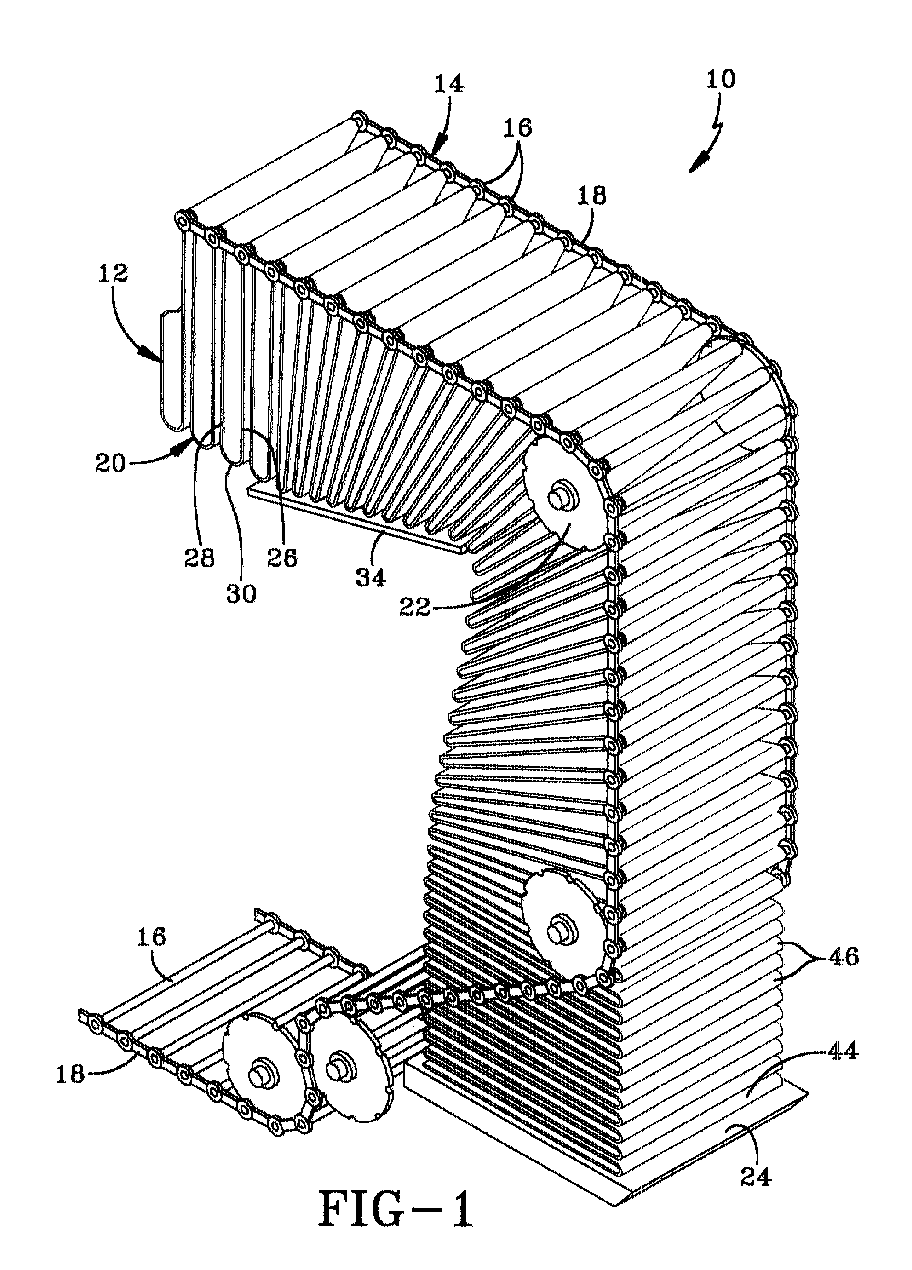
- Fig. 1 shows an apparatus 10 for performing the preferred method of the invention.
- at least one strip of flexible material 12 has been placed on a festoon type conveyor 14.
- the festoon type conveyor 14 consists of a series of parallel bars 16, or other like supports, that are held between two drive chains 18.
- the drive chains 18 are driven by at least one motor driven pulley.
- the flexible material 12 is allowed to suspend loosely between the respective bars 16 to form a number of festoons 20.
- the respective bars 16 of the conveyor 14 that provide support for the festoons 20 of flexible material 12 are referred to as material supporting bars.
- the festoons 20 are conveyed along a path of the conveyor 14 such that the orientation of the festoons 20 is maintained.
- the orientation of the respective festoons 20 is changed as the respective material supporting bars 16 travel around a pulley 22 and begins to move in a downward direction toward a stacking surface 24.
- the material supporting bar 16 for a leading surface 26 of each festoon 20 travels to a position below the material supporting bar 16 for a trailing surface 28 of that respective festoon 20.
- each festoon 20 lies on either the trailing surface 28 of a preceding festoon or, where there is no preceding festoon, on a preceding bar 32 on the conveyor 14.
- a preceding festoon is a festoon on the conveyor immediately preceding the festoon at issue.
- This change in orientation of the respective festoons 20 may be aided by the use of a deflection surface 34.
- the deflection surface 34 may be used to help separate the respective festoons 20 when the orientation is changed, especially when the flexible material 12 has an adhesive characteristic. The use of the deflection surface 34 will allow freer movement of each festoon 20.
- a movable stacking surface 24 is used to contact an initial flap 36 of the flexible material 12.
- the initial flap 36 of flexible material 12 is located between a leading edge 38 of the flexible material 12 and the first material supporting bar 40.
- the first material supporting bar 40 supports the initial flap 36 of flexible material 12.
- the initial flap 36 of the flexible material 12 will be lying against the preceding bar 32 on the conveyor 14.
- the preceding bar 32 is the bar 16 not supporting any flexible material 12, immediately preceding the first material supporting bar 40.
- the movable stacking surface 24 is inserted into an area between the first material supporting bar 40 and the proceeding bar 32.
- the stacking surface 24 moves with the proceeding bar 32 until making contact with the initial flap 36 and causing the initial flap 36 to lie flatly upon its surface.
- either the conveyor 14 or the stacking surface 24 moves such that the first material supporting bar 40 moves in a horizontal direction relative to the stacking surface 24.
- the first material supporting bar 40 is moved in a horizontal direction relative to the stacking surface 24, it is removed from the stack of flexible material 12. After complete removal from the stack, the first material supporting bar 40 no longer needs to be moved in a direction horizontal to the stacking surface 24 and may be moved in any direction.
- a first festoon 42 has a leading surface 26 that is lying on the initial flap 36 of flexible material 12.
- the first festoon 42 moves with the initial flap 36 into a position above the initial flap 36 on the stacking surface 24.
- the respective material supporting bars place this first festoon 42 on the initial flap 36 of flexible material 12, creating a first folded member 44.
- the leading surface 26 of the first festoon 42 lies directly on top of the initial flap 36 and the trailing surface 28 of the first festoon 42 continues to support the next festoon. As seen in Fig.
- the stacking surface 24 moves down such that the respective material supporting bar is moved in a horizontal direction with respect to the stacking surface 24 and is removed from the respective folded member 46.
- Each festoon is placed on the preceding festoon to create additional folded members 46.
- the conveyor 14 may be moved upward, as long as the movement of the respective material supporting bars, after laying down their respective festoons 20, is in a horizontal direction relative the stacking surface 24. It is preferred that the stacking surface 24 move down with respect to the conveyor 14 until it has reached a low point, as depicted in Fig. 4. After the stacking surface 24 has reached the low point, the conveyor 14 will begin to move upward. This increases the number of folded members 46 that can be placed on the stacking surface 24 prior to removal of the stack.
- each bar 16 of the conveyor 14 may be a movable roller or have other similar features.
- a stack created by this method will have at least one side where all the folded members 46 are aligned. At least the side of the stack of folded members 46 where the respective material supporting bars first place the festoons 20 will be aligned.
- a stack having all sides aligned, or straight, may be created by this method by suspending a predetermined amount of the flexible material 12 between the respective material supporting bars and by accurately placing the flexible material 12 in the same area of each material supporting bar on the conveyor 14.
- the first stack 48 may be removed and a new stack 50 started without stopping the conveyor 14.
- a new stacking surface 52 is inserted into the area between two of the respective material supporting bars to support the flexible material 12.
- the flexible material 12 is cut at the location of the new stacking surface 52.
- the flexible material 12 below the new stacking surface 52 is placed upon the first stack 48 and the remaining portion of flexible material 12 is stacked upon the new stacking surface 52.
- the first stack 48 is quickly removed from the area directly under the new stacking surface 52.
- either the new stacking surface 52 can be moved down, away from the conveyor 14 or, as shown in Fig. 6, both the conveyor 14 and the stacking surface 24 can be moved down to a reset position similar to that depicted in Fig. 3.
- the method of this invention converts at least one strip of flexible material 12 into at least one stack of folded members 46.
- the method results in a neater stack of folded members 46, having at least one side where all of the folded members 46 are aligned. If the flexible material 12 is neatly stacked, the narrow strips formed from the stacked material will be more uniform and will not be overlapped by other strips. As a result, the amount of manual labor needed to feed these strips into an injection molding machine is reduced. Additionally, the method eliminates the need for a belt conveyor and a wigwag device currently used to stack a respective strip of flexible material 12 so capital costs and floor space will be saved.
Landscapes
- Engineering & Computer Science (AREA)
- Mechanical Engineering (AREA)
- Folding Of Thin Sheet-Like Materials, Special Discharging Devices, And Others (AREA)
- Injection Moulding Of Plastics Or The Like (AREA)
Abstract
Description
If the second narrow strip overlaps the first narrow strip, the first narrow strip will likely break when being drawn into the injection molding machine. The overlap of the second narrow strip applies a tension to the first narrow strip of flexible material causing it to stretch and break. If the first narrow strip breaks, the remaining end of the strip must be manually fed into the inlet of the injection molding machine. If the wide strip of rubber is stacked prior to being cut, the stacks must be neat to assure that when cut, the narrow strips will have a relatively uniform width. If the rubber is sloppily stacked, cutting the stack at various points will result in narrow strips with their widths varying along their length. A single strip could have a width of one inch at one point and a width of ten inches at another point. As a result, the narrow strip may easily break when being drawn into the injection molding machine or the strip may be too wide to properly fit into the inlet of the injection molding machine. In either case, manual labor may be required to either feed the remaining end of the narrow strip into the injection molding machine or to trim the narrow strip down to a size that the injection molding machine can utilize.
Claims (4)
- A method of converting at least one strip of flexible material (12) into at least one stack of folded members (46), the method including the step of:(i) conveying a number of festoons (20) formed from a strip of flexible material (12); the method being characterized by the step of:(ii) depositing the respective festoons (20) into a stack of folded members (46).
- A method as set forth in claim 1, the step of depositing the respective festoons (20) into a stack of folded members (46) being further characterized by the steps of:(i) laying an initial flap (36) of flexible material (12) on a stacking surface (24);(ii) creating a first folded member (44) by placing a first festoon (42) on the initial flap (36) of flexible material (12);(iii) creating additional folded members by placing each festoon upon a preceding festoon.
- A method as set forth in claim 2, the step of laying an initial flap (36) of flexible material (12) on a stacking surface (24) being further characterized by the steps of:(i) contacting an initial flap (36) of the flexible material (12) with a movable stacking surface (24);(ii) moving the stacking surface (24) to cause the initial flap (36) of flexible material (12) to lie flatly on the stacking surface (24).
- A method as set forth in claim 1 being further characterized by the step of:
(i) forming the festoons (20) from a predetermined amount of the flexible material (12).
Applications Claiming Priority (2)
| Application Number | Priority Date | Filing Date | Title |
|---|---|---|---|
| US491220 | 1983-05-03 | ||
| US09/491,220 US6341771B1 (en) | 2000-01-25 | 2000-01-25 | Method of stacking strips of flexible material |
Publications (2)
| Publication Number | Publication Date |
|---|---|
| EP1120373A2 true EP1120373A2 (en) | 2001-08-01 |
| EP1120373A3 EP1120373A3 (en) | 2004-03-31 |
Family
ID=23951260
Family Applications (1)
| Application Number | Title | Priority Date | Filing Date |
|---|---|---|---|
| EP20010100807 Withdrawn EP1120373A3 (en) | 2000-01-25 | 2001-01-15 | Method of stacking strips of flexible material |
Country Status (4)
| Country | Link |
|---|---|
| US (1) | US6341771B1 (en) |
| EP (1) | EP1120373A3 (en) |
| JP (1) | JP2001270654A (en) |
| BR (1) | BR0100092A (en) |
Families Citing this family (3)
| Publication number | Priority date | Publication date | Assignee | Title |
|---|---|---|---|---|
| US6925784B2 (en) * | 2003-09-11 | 2005-08-09 | The Procter & Gamble Company | Flexible manufacturing system for consumer packaged products |
| US8388784B2 (en) * | 2008-12-23 | 2013-03-05 | The Goodyear Tire & Rubber Company | Method for retreading a tire |
| US20100154950A1 (en) * | 2008-12-23 | 2010-06-24 | D Sidocky Richard Michael | Retread cushion laminate |
Family Cites Families (18)
| Publication number | Priority date | Publication date | Assignee | Title |
|---|---|---|---|---|
| US1880820A (en) | 1929-08-26 | 1932-10-04 | Brown Harold D | Looper |
| US2196921A (en) | 1938-10-29 | 1940-04-09 | Proctor & Schwartz Inc | Web handling apparatus |
| US2993356A (en) | 1957-08-31 | 1961-07-25 | Archibald David Walter | Apparatus for wet-treating webs of sheet material |
| US3032337A (en) | 1959-05-04 | 1962-05-01 | Voit Rubber Corp | Continuous stacking system |
| US4166561A (en) | 1977-01-13 | 1979-09-04 | Bruckner Apparatebau Gmbh | Apparatus for treating a web of textile material in a dwell zone |
| US4444388A (en) | 1981-09-15 | 1984-04-24 | Bell & Howell Company | Stacking methods and apparatus |
| GB2171396B (en) | 1985-02-23 | 1988-11-23 | Unisys Corp | Self-aligning document stacker |
| DE3524246A1 (en) * | 1985-07-06 | 1987-01-08 | Will E C H Gmbh & Co | METHOD AND DEVICE FOR ZIGZAG FOLDING ENDLESS MATERIALS |
| DE3614655A1 (en) * | 1986-04-30 | 1987-11-05 | Goebel Gmbh Maschf | DEVICE FOR DEPOSITING PRODUCTS |
| US4805894A (en) | 1986-06-12 | 1989-02-21 | Transtechnology Corporation | Stacking methods and apparatus |
| CH671564A5 (en) | 1986-07-21 | 1989-09-15 | Ferag Ag | |
| DE3718081A1 (en) * | 1987-05-29 | 1988-12-08 | Will E C H Gmbh & Co | DEVICE FOR FORMING A STACK FROM A FOLDED CONTINUOUS ROAD |
| US5242366A (en) * | 1989-07-07 | 1993-09-07 | Asahi Kogaku Kogyo Kabushiki Kaisha | Mechanism for folding continuous-form sheet |
| US5058872A (en) * | 1989-08-08 | 1991-10-22 | Didde Web Press Corp. | Chain cam |
| US5558318A (en) * | 1991-01-15 | 1996-09-24 | Roll Systems, Inc. | Separator for forming discrete stacks of folded web |
| NL9301400A (en) * | 1993-08-12 | 1995-03-01 | Vmi Epe Holland | Device for cooling and stacking a rubber sheet. |
| JP2804235B2 (en) * | 1994-11-29 | 1998-09-24 | 住友ゴム工業株式会社 | Rubber sheet cooling device for tire components |
| EP0768261A1 (en) * | 1995-10-12 | 1997-04-16 | Solipat Ag | Device and method for continuous zig-zag folding and stacking of web-shaped goods |
-
2000
- 2000-01-25 US US09/491,220 patent/US6341771B1/en not_active Expired - Fee Related
-
2001
- 2001-01-15 EP EP20010100807 patent/EP1120373A3/en not_active Withdrawn
- 2001-01-17 BR BR0100092A patent/BR0100092A/en active Search and Examination
- 2001-01-19 JP JP2001011395A patent/JP2001270654A/en active Pending
Also Published As
| Publication number | Publication date |
|---|---|
| EP1120373A3 (en) | 2004-03-31 |
| US6341771B1 (en) | 2002-01-29 |
| JP2001270654A (en) | 2001-10-02 |
| BR0100092A (en) | 2001-08-28 |
Similar Documents
| Publication | Publication Date | Title |
|---|---|---|
| US10377602B2 (en) | Up-stacker for forming stacks of sheets and method | |
| US2852256A (en) | Art of delivering flexible sheets | |
| US10287113B2 (en) | Sheet stacker and method for forming stacks of sheets | |
| US5221079A (en) | Apparatus for braking a succession of sheets to be stacked | |
| US6230596B1 (en) | Method of and apparatus for conveying flat pieces of a web | |
| JPH03256925A (en) | Method and device for unloading flat product onto pile pallet | |
| US6223500B1 (en) | Apparatus and method for wrapping compressible articles with a web-like wrapping material | |
| KR102380336B1 (en) | Automated process system for manufacturing of a hand towel | |
| US6341771B1 (en) | Method of stacking strips of flexible material | |
| US6155551A (en) | Reciprocating stacker for continuous strip material | |
| JPH04266358A (en) | Device for automatic supply of stacked body of cut sheet to user unit | |
| US9776821B2 (en) | Device for stream-feeding and placing sheets onto a stack | |
| US5701717A (en) | Assembly of a loading means and a strip stacker | |
| US5904312A (en) | Reel slitter | |
| EP3147244B1 (en) | Sheet stacker and method for forming stacks of staggered bundles | |
| US5601397A (en) | Apparatus for counting and stacking tortillas | |
| WO2023175630A1 (en) | A paper sheeter machine with improved air shower assembly and method thereof | |
| JPH0696410B2 (en) | Automatic palletizer device | |
| JP2000203714A (en) | Equipment for transporting long objects | |
| JP2000128411A (en) | Stacking equipment for sheet-like conveyed goods | |
| JPH0853265A (en) | Assembly of loading means and band stacking apparatus and band stacking apparatus used for the assembly | |
| EP0638504B1 (en) | Device for cooling and stacking a sheet of rubber | |
| CN1070418C (en) | Layered product distributing machine | |
| US20210245959A1 (en) | Discharge Belt for a Palletising Device | |
| JPH068913A (en) | Half-wrapping method for bag-packaged products |
Legal Events
| Date | Code | Title | Description |
|---|---|---|---|
| PUAI | Public reference made under article 153(3) epc to a published international application that has entered the european phase |
Free format text: ORIGINAL CODE: 0009012 |
|
| AK | Designated contracting states |
Kind code of ref document: A2 Designated state(s): AT BE CH CY DE DK ES FI FR GB GR IE IT LI LU MC NL PT SE TR |
|
| AX | Request for extension of the european patent |
Free format text: AL;LT;LV;MK;RO;SI |
|
| PUAL | Search report despatched |
Free format text: ORIGINAL CODE: 0009013 |
|
| RIC1 | Information provided on ipc code assigned before grant |
Ipc: 7B 65H 20/24 B Ipc: 7B 65H 45/101 A |
|
| AK | Designated contracting states |
Kind code of ref document: A3 Designated state(s): AT BE CH CY DE DK ES FI FR GB GR IE IT LI LU MC NL PT SE TR |
|
| AX | Request for extension of the european patent |
Extension state: AL LT LV MK RO SI |
|
| 17P | Request for examination filed |
Effective date: 20040930 |
|
| AKX | Designation fees paid |
Designated state(s): DE FR GB IT |
|
| GRAP | Despatch of communication of intention to grant a patent |
Free format text: ORIGINAL CODE: EPIDOSNIGR1 |
|
| STAA | Information on the status of an ep patent application or granted ep patent |
Free format text: STATUS: THE APPLICATION IS DEEMED TO BE WITHDRAWN |
|
| 18D | Application deemed to be withdrawn |
Effective date: 20060304 |