EP1120254A1 - Ring mark printing device for identifying electrical cables - Google Patents
Ring mark printing device for identifying electrical cables Download PDFInfo
- Publication number
- EP1120254A1 EP1120254A1 EP01400184A EP01400184A EP1120254A1 EP 1120254 A1 EP1120254 A1 EP 1120254A1 EP 01400184 A EP01400184 A EP 01400184A EP 01400184 A EP01400184 A EP 01400184A EP 1120254 A1 EP1120254 A1 EP 1120254A1
- Authority
- EP
- European Patent Office
- Prior art keywords
- ink
- cylindrical body
- ring
- mark printing
- orifice
- Prior art date
- Legal status (The legal status is an assumption and is not a legal conclusion. Google has not performed a legal analysis and makes no representation as to the accuracy of the status listed.)
- Withdrawn
Links
Images





Classifications
-
- H—ELECTRICITY
- H01—ELECTRIC ELEMENTS
- H01B—CABLES; CONDUCTORS; INSULATORS; SELECTION OF MATERIALS FOR THEIR CONDUCTIVE, INSULATING OR DIELECTRIC PROPERTIES
- H01B13/00—Apparatus or processes specially adapted for manufacturing conductors or cables
- H01B13/34—Apparatus or processes specially adapted for manufacturing conductors or cables for marking conductors or cables
- H01B13/345—Apparatus or processes specially adapted for manufacturing conductors or cables for marking conductors or cables by spraying, ejecting or dispensing marking fluid
-
- B—PERFORMING OPERATIONS; TRANSPORTING
- B41—PRINTING; LINING MACHINES; TYPEWRITERS; STAMPS
- B41F—PRINTING MACHINES OR PRESSES
- B41F17/00—Printing apparatus or machines of special types or for particular purposes, not otherwise provided for
- B41F17/08—Printing apparatus or machines of special types or for particular purposes, not otherwise provided for for printing on filamentary or elongated articles, or on articles with cylindrical surfaces
- B41F17/10—Printing apparatus or machines of special types or for particular purposes, not otherwise provided for for printing on filamentary or elongated articles, or on articles with cylindrical surfaces on articles of indefinite length, e.g. wires, hoses, tubes, yarns
-
- B—PERFORMING OPERATIONS; TRANSPORTING
- B41—PRINTING; LINING MACHINES; TYPEWRITERS; STAMPS
- B41J—TYPEWRITERS; SELECTIVE PRINTING MECHANISMS, i.e. MECHANISMS PRINTING OTHERWISE THAN FROM A FORME; CORRECTION OF TYPOGRAPHICAL ERRORS
- B41J2/00—Typewriters or selective printing mechanisms characterised by the printing or marking process for which they are designed
- B41J2/005—Typewriters or selective printing mechanisms characterised by the printing or marking process for which they are designed characterised by bringing liquid or particles selectively into contact with a printing material
- B41J2/01—Ink jet
-
- B—PERFORMING OPERATIONS; TRANSPORTING
- B41—PRINTING; LINING MACHINES; TYPEWRITERS; STAMPS
- B41J—TYPEWRITERS; SELECTIVE PRINTING MECHANISMS, i.e. MECHANISMS PRINTING OTHERWISE THAN FROM A FORME; CORRECTION OF TYPOGRAPHICAL ERRORS
- B41J3/00—Typewriters or selective printing or marking mechanisms characterised by the purpose for which they are constructed
- B41J3/407—Typewriters or selective printing or marking mechanisms characterised by the purpose for which they are constructed for marking on special material
Definitions
- the invention relates to a ring-mark printing device for identifying electrical cables.
- ring marks are to be painted on the circular surface of an electrical cable, the operation is preferably carried out under noncontact conditions.
- the electrical cables painted with ring marks are usually employed in the automobile industry, and the ring marks serve to distinguish the quality and/or size of such cables.
- Known ring-mark printing devices usually employ either a printing system in which ink is ejected through ink nozzles under pressure and painted on a cable surface, or a system in which a marking drum is provided with a cylindrical surface having ink nozzles, through which ink is ejected by the centrifugal force exerted by drum rotation.
- first printing system An example of the former (first) printing system is disclosed in a Japanese utility model application published under No. SHO 61-60413, and an example of the latter (second) system is disclosed in a Japanese utility model application published under No. HEI 7-25517.
- Fig. 1 shows process steps performed by the second printing system, in which an electrical cable is manufactured and then painted with ring-like marks.
- a conductor wire 2 is continuously supplied from a supply reel 1 along a predetermined path.
- the conductor wire 2 is then passed through an extruding machine 3 and coated while being extruded, thereby yielding a coated electrical cable 4.
- the coated electrical cable 4 is guided into a printer machine 5, in which the cable is painted with ring-like marks used for cable identification.
- the marked electrical cable 4 is cooled in a cooling bath 6, withdrawn through a withdrawal unit 7, and reeled continuously around a receiving reel 8.
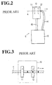
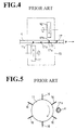
- Figs. 2, 3 and 4 illustrate the following device units : a printer box 10, in which the electrical cable 4 is subjected to a printing operation; a pair of marking drums 11 and 12 mounted in the printer box 10, the two marking drums being arranged sequentially along the cable's feed axis, and in staggered positions and at some distance relative to the feed axis; a driving mechanism for rotating both marking drums 11 and 12 (not shown in the figures); an ink tank 13 for storing marking ink; an ink-supply mechanism for feeding ink from the ink tank 13 to inside the marking drums 11 and 12 through a supply pipe 14; and an ink return pipe 15 for forwarding the ink contained in the printer box 10 to the ink tank 13.
- the marking drums 11 and 12 respectively include a plurality of ink-jet nozzles (six nozzles in the illustrated example) arranged at a given interval in the circumferential direction of the cylindrical surface.
- the ink 16 stored in the marking drum 11 is ejected through each ink-jet nozzle, by virtue of the centrifugal force generated by the rotating drum, so that each half side face of the electrical cable 4, when advancing along the feed axis P, is painted with ejected ink.
- Figs. 3 to 7 show in more detail this marking process.
- a first semicircular side face of the cable 4 is painted with ink 16 ejected from the marking drum 11 placed upstream, and printed with a semicircular mark 17a (Fig. 5).
- a second semicircular side face of the cable 4 is painted with ink 16 ejected from the marking drum 12, and printed with a semicircular mark 17b (Fig. 6).
- the outer circular face of the electrical cable 4 can be printed with complete ring marks 17 (or band marks) at a given interval.
- the marking drums 11 and 12 are driven in synchronization.
- the printer device 5 may be turned off optionally when the electrical cables are to be processed without printing.
- this switching off process involves a certain time lag before the rotational speed of the marking drums 11 and 12 can be lowered up to a point where the ink 16 stops jetting out.
- the portion of electrical cables 4 processed during that switch off time must be classed aside as a substandard product.
- the marking drums 11 and 12 are again put into motion, it takes a while before the rotation speed regain a full motion and stabilizes.
- the portion of electrical cables 4 produced during this period must also be classed aside as a substandard product. Those substandard products formed during the restarting period may reach several kilometers of the electrical cable 4, which is classed as a length loss.
- ink 16 may be spattered around from the marking drums 11 and 12 while the shield is replaced, and smear peripheral equipment. As the ink 16 contains organic solvents, the working environments are also deteriorated.
- the shield when the shield is replaced, it may inadvertently thrust the electrical cable 4, and cut it off.
- the present invention provides a ring-mark printing device for identifying electrical cables, which reduces the length loss of the electrical cables, improves the running rate of the cables' production line, and is adapted to a small-lot production.
- a ring-mark printing device for identifying electrical cables.
- the device comprises a printer box having a feed axis and adapted to pass an electrical cable along the feed axis and a pair of marking drums with a respective outer circular face.
- the marking drums are contained in the printer box and arranged in staggered positions along the feed axis and at a given distance away therefrom.
- the marking drums include ink-jet nozzles at the outer circular face.
- the marking drums are respectively adapted to contain ink and eject the ink through the ink-jet nozzles by virtue of centrifugal forces exerted by drum rotation, in order to print the ring-mark around the circular surface of the electrical cable.
- the printer box is provided with an ink shield comprising substantially concentrically placed outer and inner cylindrical bodies which are adapted to surround the electrical cable from a given distance.
- the outer cylindrical body further comprises at least one outer ink-orifice at a position facing one of the marking drums and the inner cylindrical body comprises at least one inner ink orifice.
- the inner cylindrical body is then mounted such that it can slide through the outer cylindrical body along said feed axis in a freely movable way, and such that the inner ink-orifice(s) can be joined with corresponding outer ink-orifice(s) to be ready for ring-mark printing, or biased from corresponding outer ink-orifice(s) to be hindered from ring-mark printing.
- the outer cylindrical body is divided into three outer cylindrical segments by two outer ink-orifices, and the outer cylindrical segments are held by a shield support.
- the shield support may have an opening in a portion adjacent to the outer ink-orifice(s).
- the inner cylindrical body is divided into three inner cylindrical segments by two inner ink-orifices, and the inner cylindrical segments are tied to each other by a linking means.
- the outer and inner cylindrical bodies comprise a corresponding outer and inner longitudinal slit along a diametrically lowermost portion, when in use, over the length of the corresponding body.
- the outer and inner longitudinal slits thus communicate with corresponding outer and inner ink-orifice(s).
- the outer and inner longitudinal slits then communicate to each other and have a space sufficiently large for allowing the electrical cable to pass, such that the ink shield can be fitted into the printer box from the top thereof in a freely engageable and removable way.
- the inner longitudinal slit may comprise first and second longitudinal rims, which are divided into corresponding first and second rim segments by the inner ink-orifice(s).
- first rim segments are placed farther than the second rim segments, relative to one of the marking drums.
- the linking means is then mounted between two adjacent first rim segments .
- the inner cylindrical body comprises at least one chock, such that, when it is slid through the outer cylindrical body, it can determine a position ready for ring-mark printing and a position for impeding the ring-mark printing.
- the inner cylindrical body is longer than the outer cylindrical body, so that two end portions of the former extend outwardly from two end portions of the latter along said feed axis, and the two end portions of the inner cylindrical body carry respectively first and second chocks, such that the inner cylindrical body can determine a position ready for ring-mark printing or for impeding the ring-mark printing, by sliding it until the first or second chock abuts against the outer cylindrical body.
- the embodiment uses a printing device 5 which can be as described with reference to the prior art (cf. Fig. 2), i.e. comprising: a printer box 10 in which an electrical cable 4 is subjected to a mark printing; a pair of marking drums 11 and 12 provided in the printer box 10, both drums 11 and 12 being placed sequentially along the feed axis P of the electrical cable 4 and being in a staggered position and at a given distance with respect to the feed axis; a driving mechanism for rotating the pair of marking drums 11 and 12; an ink tank 13 for storing ink 16; an ink supply mechanism for supplying ink from the ink tank 13 into the marking drums 11 and 12 through a supply pipe 14; and an ink return pipe 15 for returning the ink 16 filling the printer box 10 into the ink tank.
- a printing device 5 which can be as described with reference to the prior art (cf. Fig. 2), i.e. comprising: a printer box 10 in which an electrical cable 4 is subjected to
- the marking drums 11 and 12 are respectively provided with a plurality of ink-jet nozzles (six in the present case) arranged at a given interval in the circumferential direction of the marking drums 11 and 12.
- the ink 16 stored in the marking drums 11 and 12 is ejected through the ink-jet nozzles by virtue of the centrifugal forces exerted by rotating drums.
- a first semicircular side face thereof is painted with ink by the marking drum 11 located upstream, whereby a first semicircular mark 17a is formed.
- a second semicircular side face of the cable 4 is painted with ink by the marking drum 12 located downstream, whereby a second semicircular mark 17b is formed.
- the marking drums 11 and 12 are driven in a synchronized manner, such that the second semicircular mark 17b coincides with the first semicircular mark 17a, and the complete ring marks 17 thus formed are printed at a given interval over the length of the electrical cable 4.
- a shield-groove 20 is provided in the printer box 10, such that it extends from top of the printer box 10 (see Fig. 8) down to below the feed axis P where the electrical cable 4 passes.
- the shield groove 20 is fitted with an ink shield 21 in a freely engageable and removable way.
- the ink shield 21 surrounds and protects the electrical cable 4 passing along the feed axis P.
- the ink shield 21 comprises a double-layered shield cylinder 22, and a shield support 23 in the form of a plate, which supports the shield cylinder 22.
- the shield cylinder 22 comprises an outer cylindrical body 24 and an inner cylindrical body 25, respectively having a substantially oval-shaped cross-section. Both cylindrical bodies have an longitudinal slit at their diametrically lowermost portion, thereby forming outer slit edges and inner slit edges, and are arranged concentrically around the feed axis P. Moreover, the inner cylindrical body 25 is installed such that it can slide freely through the outer cylindrical body 24 along the feed axis P.
- the outer cylindrical body 24 and the inner cylindrical body 25 have a substantially similar shape with different scale, keeping a space of about 0.1 to 0.5 mm therebetween. Although they can be displaced along the feed axis P relative to each other, they cannot be rotated around this axis against each other. The space between them can be determined depending on the case.
- the outer cylindrical body 24 may comprise an outer ink-orifice 24a, respectively at two positions along the feed axis P.
- the inner cylindrical body 25 may comprise an inner ink orifice 25a, respectively at two positions along the feed axis P.
- Axial end portions of the inner cylindrical body 25 extend beyond the corresponding axial end portions of the outer cylindrical body 24.
- Each axial end portion of the inner cylindrical body 25 may then comprise corresponding chocks 26 and 27, respectively at a diametrical top zone thereof.
- the chocks 26 and 27 can thus define the sliding movement of the inner cylindrical body 25 relative to the outer cylindrical body 24, and determine the schedule between ring-mark printing production and non-printing production.
- the diametrically lowermost zones of the outer and inner cylindrical bodies include an outer longitudinal slit 24b and an inner longitudinal slit 25b that communicate to each other. Their opening is broad enough to let the electrical cable 4 pass through, and extend in parallel relation over the feed axis P.
- the outer cylindrical body 24 is divided into three outer cylindrical segments along the feed axis P by two outer ink-orifices 24a. All the three outer cylindrical segments are integrally linked by e.g. welding with a rim portion of the shield support 23. The portions of shield support 23 adjacent to the outer ink-orifices 24a are cut out to form openings 23a and 23b with enough space, so as not to hinder the trajectory of ejected ink 16.
- the openings 23a and 23b have respectively a diagonally cut cross-section, viewed from a side elevational face of the shield support 23. Accordingly, when ink is projected, and shuttered by the shield support 23, the ink is prevented from dropping on the electrical cable 4.
- the inner cylindrical body 25 may include two inner ink-orifices 25a, thus defining three inner cylindrical segments, and is configured such that it can slide freely through each outer cylindrical segment of the outer cylindrical body 24.
- the three inner cylindrical segments are bound to each other through two links 25c.
- Each of the links 25c is tied to one of the inner slit edges of inner cylindrical segments, which is located farthest from the marking drum 11 or 12.
- the width of the links 25c is determined as a function of the strength required for the application.
- two vertical side ends (in a side elevational view) of the shield support 23 are flanked with a side board 29 and fixed with bolts thereto in a freely engageable or removable way.
- the fit channel 20 is further provided with vertical sub-channels 10a at the opposing sides of the fit channel 20, so that when the shield 21 is fitted into the fit channel 20 from top of the printer box 10, the side boards 29 are fitted into the sub-channels 10a. In this manner, the shield support 23 is prevented from biasing along the feed axis P.
- shield support 23 in a side elevational view, opposed to its bottom end where the outer cylinder portion 24 is attached, is mounted with a shield-fitting tab 30.
- the shield 21 can be fitted into the printer box 10 or removed therefrom by handling this tab 30.
- the shield-fitting tab 30 is made of a bolt freely engageable into or removable from the shield support 23 by screwing.
- the links 25c and their longitudinal rim zones, as well as the slit edges of the inner longitudinal slit 25b, are tilted inwards and made into a round configuration. This can be achieved by hammering the angles of the edges. Such a configuration permits to efficiently prevent the electrical cable 4 from being hooked and cut off.
- the ink shield 21 is lodged in the fit channel 20 of the printer box 10.
- the electrical cable 4 passes along the feed axis, concentric axis for the outer cylindrical body 24 and inner cylindrical body 25.
- the inner cylindrical body 25 is slid relative to the outer cylindrical body, until the chock 26 abuts against the side face of the shield support 23.
- the outer ink-orifice 24a and the inner ink-orifice 25a are thus made to communicate with each other, so that the electrical cable 4 can be printed with ring marks.
- the electrical cable 4 passes through the shield cylinder 22 and arrives at the position where the marking drum 11 is located. Ink 16 is then ejected from the marking drum 11 by its centrifugal forces. The ink 16 is ejected through the communicated outer ink-orifice 24a and inner ink-orifice 25a, and printed on a first semicircular face of the cable 4 with a half ring mark 17a. The electrical cable runs further and reaches the position where the marking drum 12 is located. In a similar way, the ink 16 is ejected through the communicated outer ink-orifice 24a and inner ink-orifice 25a, and printed on a second semicircular face of the cable 4 with another half ring mark 17b. In this manner, the electrical cable 4 is printed with completely circular ring marks 17 at a predetermined interval.
- the inner cylindrical body 25 When non-marked electrical cables are to be manufactured, the inner cylindrical body 25 is slid the other way. The chock 27 is then abutted to the other side face of the shield support 23, so that the inner ink-orifice 25a is biased from the outer ink-orifice 24a. Consequently, the outer ink-orifices 24a of the outer cylinder portion 24 is shuttered by the inner cylinder portion 25 (Fig. 12).
- the electrical cable 4 passes through the shield cylinder 22 and arrives at the position where the marking drum 11 is located. Ink 16 is then ejected from the marking drum 11 by its rotating forces. The ink 16 is ejected through the outer ink-orifice 24a, but shut out by the inner cylinder portion 25, so that the ink 16 is prevented from reaching the electrical cable 4. The electrical cable runs further and reaches the position where the marking drum 12 is located. In a similar way, the ink 16 is ejected through the outer ink-orifice 24a, but shuttered by the inner cylinder portion 25, so that the ink 16 is prevented from reaching the electrical cable 4. In this manner, the electrical cables 4 without ring mark 17 are manufactured.
- Switching between the production schedule for ring-marked cables and that for non-marked cables can thus be operated by merely sliding the inner cylindrical body 25. This one-touch operation only takes a very short time, thereby reducing the amount of unqualified products.
- the length loss for the electrical cable 4 does not exceed an extent of several meters.
- the marking drums 11 and 12 contained in the printer box 5 are rotated without interruption, so that the clogging of ink-jet nozzles, due to solidified ink, can be prevented. Moreover, the overhauling work required in the past when restarting the production line is no longer necessary.
- switching the production module by opening or closing the outer and inner ink-orifices 24a and 25a does not involve the switching of ink ejecting module.
- the cables 4 with or without ring marks 17 can be produced continuously in the same production schedule.
- the system of the invention is well adapted to a small lot production and improves running rates of the production line.
- the links 25c bridging the inner ink-orifices 25a of the inner cylindrical body 25 are formed on one of the inner slit edges, located farthest from the marking drum 11 or 12, so that ink 16 ejected from the marking drum 11 or 12 will not detoured by the links 25c. Printing performance of the ring marks 17 on the electrical cable 4 is thus further improved.
- the outer cylindrical body 24 and inner cylindrical body 25 of the shield cylinder 22 respectively have an oval-shaped cross-section.
- the cross-section may also be round, insofar as the two cylindrical bodies 24 and 25 are prevented from rotating relative to each other.
- the chocks 26 and 27 are mounted on the inner cylindrical body 25. Alternatively, they may be mounted on the outer cylindrical body 24.
- the printer box contains an ink shield including concentrically placed outer and inner cylindrical bodies.
- the outer and inner cylindrical bodies surround, from a certain distance away, an electrical cable which passes through the printer box along the cable feed axis.
- the outer cylindrical body comprises outer ink-orifices at positions placed in the trajectory of the ink ejected from the marking drums.
- the inner cylindrical body comprises inner ink-orifices, and is mounted inside the outer cylindrical body in a freely slidable way along the feed axis. Those outer and inner ink-orifices can be joined by sliding the inner cylindrical body relative to the outer cylindrical body, so that the electrical cable can receive ejected ink.
- the inner ink-orifices can be biased relative to the outer ink-orifice by sliding the inner cylindrical body, so that the electrical cable is prevented from receiving ejected ink.
- Switching of the schedule between mark-on mode and mark-off mode can be done by one-touch operation, i.e. merely by sliding the inner cylindrical body. The switching time thus becomes very short, so that the length loss of electrical cables, arising from the generation of substandard products, is drastically reduced.
- the hybrid production of marked and off-mark electrical cables can be carried out continuously and length loss of the cables can be reduced, the production schedule can be adapted more easily to a small lot production. As a consequence, running rates of the production line can be improved.
- the diametrically lowermost portions of the respective outer and inner cylindrical bodies are provided with a corresponding longitudinal slit in parallel relation over the feed axis of the electrical cable. These slits are collocated to each other, and have a space large enough to bring the electrical cable into the inner cylindrical body. In this manner, the ink shield can be inserted into the printer box from the top thereof, or removed therefrom, in an easily transformable way. Maintenance of the printer box is thus greatly facilitated.
- the outer cylindrical body is divided into three outer segments by two outer ink-orifices, whilst the inner cylindrical body is divided into three inner segments by two inner ink-orifices.
- the inner cylindrical body is then maintained in the outer cylindrical body such that it can slide through the three outer segments.
- the three inner segments are linked through only one of the slit edges located farthest from the ink-jet nozzles. The link portions do not therefore impede the ink trajectory when the ring marks are printed.
- the sliding movement of the inner cylindrical body is defined by positioning the chocks, such that marking position and off-mark position are also determined.
- the production schedule can thus be changed very easily by a simple sliding operation.
Landscapes
- Engineering & Computer Science (AREA)
- Manufacturing & Machinery (AREA)
- Manufacturing Of Electric Cables (AREA)
- Dot-Matrix Printers And Others (AREA)
- Insulated Conductors (AREA)
- Ink Jet (AREA)
Abstract
A ring-mark printing device (5) for identifying electrical cables (4)
comprises a printer box (10) having a feed axis (P) and adapted to pass an
electrical cable (4) along the feed axis (P). The printer box (10) includes an
ink shield (21) comprising a concentrically arranged double structured
cylinder. The double structured cylinder includes an outer cylindrical body
(24), and an inner cylindrical body (25), the latter (25) being held such that
it can freely slide through the outer cylindrical body (24). The outer
cylindrical (24) body includes outer ink-orifices (24a) at positions facing
marking drums (11, 12). The inner cylindrical body (25) also includes
inner ink-orifices (25a). By sliding the inner cylindrical body (25), an
inner ink-orifice (25a) can be joined with an outer ink-orifice (24a), so that
the electrical cable (4) is ready to be printed with ink (16) ejected from the
marking drum (11, 12), or biased from the outer ink-orifice (24a), so that
the electrical cable (4) is impeded from printing. In this manner,
production of substandard electrical cable is greatly reduced, and running
rates of the production line is improved. Further, the operation process is
well adapted to a small lot production.
Description
- The invention relates to a ring-mark printing device for identifying electrical cables. When ring marks are to be painted on the circular surface of an electrical cable, the operation is preferably carried out under noncontact conditions. The electrical cables painted with ring marks are usually employed in the automobile industry, and the ring marks serve to distinguish the quality and/or size of such cables.
- Known ring-mark printing devices usually employ either a printing system in which ink is ejected through ink nozzles under pressure and painted on a cable surface, or a system in which a marking drum is provided with a cylindrical surface having ink nozzles, through which ink is ejected by the centrifugal force exerted by drum rotation.
- An example of the former (first) printing system is disclosed in a Japanese utility model application published under No. SHO 61-60413, and an example of the latter (second) system is disclosed in a Japanese utility model application published under No. HEI 7-25517.
- Fig. 1 shows process steps performed by the second printing system, in which an electrical cable is manufactured and then painted with ring-like marks. In this system, a
conductor wire 2 is continuously supplied from a supply reel 1 along a predetermined path. Theconductor wire 2 is then passed through anextruding machine 3 and coated while being extruded, thereby yielding a coatedelectrical cable 4. The coatedelectrical cable 4 is guided into aprinter machine 5, in which the cable is painted with ring-like marks used for cable identification. The markedelectrical cable 4 is cooled in acooling bath 6, withdrawn through awithdrawal unit 7, and reeled continuously around a receivingreel 8. - Figs. 2, 3 and 4 illustrate the following device units : a
printer box 10, in which theelectrical cable 4 is subjected to a printing operation; a pair of markingdrums printer box 10, the two marking drums being arranged sequentially along the cable's feed axis, and in staggered positions and at some distance relative to the feed axis; a driving mechanism for rotating both markingdrums 11 and 12 (not shown in the figures); anink tank 13 for storing marking ink; an ink-supply mechanism for feeding ink from theink tank 13 to inside the markingdrums supply pipe 14; and anink return pipe 15 for forwarding the ink contained in theprinter box 10 to theink tank 13. - As shown in Figs. 5 and 6, the marking
drums ink 16 stored in the markingdrum 11 is ejected through each ink-jet nozzle, by virtue of the centrifugal force generated by the rotating drum, so that each half side face of theelectrical cable 4, when advancing along the feed axis P, is painted with ejected ink. - Figs. 3 to 7 show in more detail this marking process. When the
electrical cable 4 advances along the feed axis P of the cable and passes in front of a first markingdrum 11, a first semicircular side face of thecable 4 is painted withink 16 ejected from the markingdrum 11 placed upstream, and printed with asemicircular mark 17a (Fig. 5). Likewise, when theelectrical cable 4 advances further and passes in front of a second markingdrum 12 placed downstream, a second semicircular side face of thecable 4 is painted withink 16 ejected from themarking drum 12, and printed with asemicircular mark 17b (Fig. 6). In this manner, the outer circular face of theelectrical cable 4 can be printed with complete ring marks 17 (or band marks) at a given interval. - In order to match the position of the first
semicircular mark 17a with that of the secondsemicircular mark 17b, the markingdrums - In such a centrifugal printing system, equipment is designed with the presumption that the
ink 16 continues to be ejected correctly. Accordingly, whenelectrical cables 4 with and without ring marks are produced in the same production line, either theprinter device 5 is cut off, or a special ink-shield is installed for deviating ejectedink 16 from theelectrical cable 4. - Thus, when the centrifugal printing system is applied, the
printer device 5 may be turned off optionally when the electrical cables are to be processed without printing. However, this switching off process involves a certain time lag before the rotational speed of the markingdrums ink 16 stops jetting out. As a result, the portion ofelectrical cables 4 processed during that switch off time must be classed aside as a substandard product. Conversely, when the markingdrums electrical cables 4 produced during this period must also be classed aside as a substandard product. Those substandard products formed during the restarting period may reach several kilometers of theelectrical cable 4, which is classed as a length loss. - When the marking
drums - When a special ink shield is used, it must be replaced during a replacement standstill. Such a standstill incurs of course the production of substandard electrical cables, resulting in a length loss of several hundred meters. Moreover,
ink 16 may be spattered around from the markingdrums ink 16 contains organic solvents, the working environments are also deteriorated. - Moreover, when the shield is replaced, it may inadvertently thrust the
electrical cable 4, and cut it off. - In order to reduce such kind of accident, prior art methods usually opted for preparing different production schedules, depending on whether
electrical cables 4 are printed with ring marks or not. However, such production methods are not well adapted to a small-lot production and suffer from a low running rate of the production line. - In view of solving such problems, the present invention provides a ring-mark printing device for identifying electrical cables, which reduces the length loss of the electrical cables, improves the running rate of the cables' production line, and is adapted to a small-lot production.
- To this end, there is provided a ring-mark printing device for identifying electrical cables. The device comprises a printer box having a feed axis and adapted to pass an electrical cable along the feed axis and a pair of marking drums with a respective outer circular face. The marking drums are contained in the printer box and arranged in staggered positions along the feed axis and at a given distance away therefrom. Further, the marking drums include ink-jet nozzles at the outer circular face. Further yet, the marking drums are respectively adapted to contain ink and eject the ink through the ink-jet nozzles by virtue of centrifugal forces exerted by drum rotation, in order to print the ring-mark around the circular surface of the electrical cable.
- According to the invention, the printer box is provided with an ink shield comprising substantially concentrically placed outer and inner cylindrical bodies which are adapted to surround the electrical cable from a given distance. The outer cylindrical body further comprises at least one outer ink-orifice at a position facing one of the marking drums and the inner cylindrical body comprises at least one inner ink orifice.
- The inner cylindrical body is then mounted such that it can slide through the outer cylindrical body along said feed axis in a freely movable way, and such that the inner ink-orifice(s) can be joined with corresponding outer ink-orifice(s) to be ready for ring-mark printing, or biased from corresponding outer ink-orifice(s) to be hindered from ring-mark printing.
- Preferably, the outer cylindrical body is divided into three outer cylindrical segments by two outer ink-orifices, and the outer cylindrical segments are held by a shield support.
- Further, the shield support may have an opening in a portion adjacent to the outer ink-orifice(s).
- Suitably, the inner cylindrical body is divided into three inner cylindrical segments by two inner ink-orifices, and the inner cylindrical segments are tied to each other by a linking means.
- Suitably yet, the outer and inner cylindrical bodies comprise a corresponding outer and inner longitudinal slit along a diametrically lowermost portion, when in use, over the length of the corresponding body. The outer and inner longitudinal slits thus communicate with corresponding outer and inner ink-orifice(s). The outer and inner longitudinal slits then communicate to each other and have a space sufficiently large for allowing the electrical cable to pass, such that the ink shield can be fitted into the printer box from the top thereof in a freely engageable and removable way.
- The inner longitudinal slit may comprise first and second longitudinal rims, which are divided into corresponding first and second rim segments by the inner ink-orifice(s). In this arrangement, the first rim segments are placed farther than the second rim segments, relative to one of the marking drums. The linking means is then mounted between two adjacent first rim segments .
- Preferably, the inner cylindrical body comprises at least one chock, such that, when it is slid through the outer cylindrical body, it can determine a position ready for ring-mark printing and a position for impeding the ring-mark printing.
- Preferably yet, the inner cylindrical body is longer than the outer cylindrical body, so that two end portions of the former extend outwardly from two end portions of the latter along said feed axis, and the two end portions of the inner cylindrical body carry respectively first and second chocks, such that the inner cylindrical body can determine a position ready for ring-mark printing or for impeding the ring-mark printing, by sliding it until the first or second chock abuts against the outer cylindrical body.
- The above and the other objects, features and advantages of the present invention will be made apparent from the following description of the preferred embodiments, given as examples, with reference to the accompanying drawings, in which :
- Fig. 1 is a flowchart representation of a prior art production line for ring-marked electrical cables ;
- Fig. 2 is a side elevational view of a printing unit, mainly showing a printer box, contained in the production line of Fig. 1 ;
- Fig. 3 is an inside view of the printer box of Fig. 2, mainly showing two marking drums ;
- Fig. 4 is an inside top plan view of the printer box of Fig. 3 ;
- Fig. 5 is a side elevational view of a first marking drum of Figs. 3 and 4, showing how a semicircular mark is printed ;
- Fig. 6 is a side elevational view of a second marking drum of Figs. 3 and 4, showing how a second semicircular mark is printed ;
- Fig. 7 is a side view of an electrical cable printed with ring marks ;
- Fig. 8 is a side elevational view of a printing unit according to the invention, when an ink shield is being fitted into a printer box ;
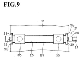
- Fig. 9 is a top plan view of an ink shield, when it is fitted into the printing box ;
- Fig. 10 is a side elevational view of the front face of an ink shield according to the invention, when the ink orifices of the outer cylindrical body and those of the inner cylindrical body are joined ;
- Fig. 11 is a side elevational view of the side face of an ink shield according to the invention ;
- Fig. 12 is a side elevational view of the front face of an ink shield according to the invention, when the ink orifices of the outer cylindrical body are biased from those of the inner cylindrical body ;
- Fig. 13 is a side elevational front view of a shield support and the outer cylindrical body connected thereto ;
- Fig. 14 is a side elevational lateral view of the shield support of Fig. 13;
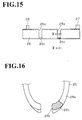
- Fig. 15 is a side elevational view of an inner cylindrical body according to the invention ; and
- Fig. 16 is a partial view of a cross-section of the slit edges, taken along line IX in the inner cylindrical body of Fig. 15.
-
- The embodiment uses a
printing device 5 which can be as described with reference to the prior art (cf. Fig. 2), i.e. comprising: aprinter box 10 in which anelectrical cable 4 is subjected to a mark printing; a pair of markingdrums printer box 10, bothdrums electrical cable 4 and being in a staggered position and at a given distance with respect to the feed axis; a driving mechanism for rotating the pair of markingdrums ink tank 13 for storingink 16; an ink supply mechanism for supplying ink from theink tank 13 into the marking drums 11 and 12 through asupply pipe 14; and anink return pipe 15 for returning theink 16 filling theprinter box 10 into the ink tank. - The marking drums 11 and 12 are respectively provided with a plurality of ink-jet nozzles (six in the present case) arranged at a given interval in the circumferential direction of the marking drums 11 and 12. The
ink 16 stored in the marking drums 11 and 12 is ejected through the ink-jet nozzles by virtue of the centrifugal forces exerted by rotating drums. As theelectrical cable 4 progresses along the feed axis P, each half of its circular face is painted with the ejected ink. - Thus, as the
electrical cable 4 moves along, a first semicircular side face thereof is painted with ink by the markingdrum 11 located upstream, whereby a firstsemicircular mark 17a is formed. Likewise, a second semicircular side face of thecable 4 is painted with ink by the markingdrum 12 located downstream, whereby a secondsemicircular mark 17b is formed. - The marking drums 11 and 12 are driven in a synchronized manner, such that the second
semicircular mark 17b coincides with the firstsemicircular mark 17a, and the complete ring marks 17 thus formed are printed at a given interval over the length of theelectrical cable 4. - As shown in Figs. 8 to 16, a shield-
groove 20 is provided in theprinter box 10, such that it extends from top of the printer box 10 (see Fig. 8) down to below the feed axis P where theelectrical cable 4 passes. Theshield groove 20 is fitted with anink shield 21 in a freely engageable and removable way. Theink shield 21 surrounds and protects theelectrical cable 4 passing along the feed axis P. - The
ink shield 21 comprises a double-layeredshield cylinder 22, and ashield support 23 in the form of a plate, which supports theshield cylinder 22. - As shown in Figs. 8, 11 and 14, the
shield cylinder 22 comprises an outercylindrical body 24 and an innercylindrical body 25, respectively having a substantially oval-shaped cross-section. Both cylindrical bodies have an longitudinal slit at their diametrically lowermost portion, thereby forming outer slit edges and inner slit edges, and are arranged concentrically around the feed axis P. Moreover, the innercylindrical body 25 is installed such that it can slide freely through the outercylindrical body 24 along the feed axis P. The outercylindrical body 24 and the innercylindrical body 25 have a substantially similar shape with different scale, keeping a space of about 0.1 to 0.5 mm therebetween. Although they can be displaced along the feed axis P relative to each other, they cannot be rotated around this axis against each other. The space between them can be determined depending on the case. - The outer
cylindrical body 24 may comprise an outer ink-orifice 24a, respectively at two positions along the feed axis P. Likewise, the innercylindrical body 25 may comprise aninner ink orifice 25a, respectively at two positions along the feed axis P. By virtue of the sliding movement of the innercylindrical body 25, ring mark printing can be started or halted with great flexibility, respectively by communicating an outer ink-orifice 24a with an inner-ink orifice 25a (Fig. 10), or by biasing those orifices (Fig. 12). - Axial end portions of the inner
cylindrical body 25 extend beyond the corresponding axial end portions of the outercylindrical body 24. Each axial end portion of the innercylindrical body 25 may then comprise correspondingchocks chocks cylindrical body 25 relative to the outercylindrical body 24, and determine the schedule between ring-mark printing production and non-printing production. - As mentioned above, the diametrically lowermost zones of the outer and inner cylindrical bodies include an outer
longitudinal slit 24b and an innerlongitudinal slit 25b that communicate to each other. Their opening is broad enough to let theelectrical cable 4 pass through, and extend in parallel relation over the feed axis P. - According to a preferred embodiment of the invention, the outer
cylindrical body 24 is divided into three outer cylindrical segments along the feed axis P by two outer ink-orifices 24a. All the three outer cylindrical segments are integrally linked by e.g. welding with a rim portion of theshield support 23. The portions ofshield support 23 adjacent to the outer ink-orifices 24a are cut out to formopenings ink 16. - The
openings shield support 23. Accordingly, when ink is projected, and shuttered by theshield support 23, the ink is prevented from dropping on theelectrical cable 4. - Similarly, the inner
cylindrical body 25 may include two inner ink-orifices 25a, thus defining three inner cylindrical segments, and is configured such that it can slide freely through each outer cylindrical segment of the outercylindrical body 24. The three inner cylindrical segments are bound to each other through twolinks 25c. Each of thelinks 25c is tied to one of the inner slit edges of inner cylindrical segments, which is located farthest from the markingdrum links 25c is determined as a function of the strength required for the application. - As shown in Figs. 8 to 12, two vertical side ends (in a side elevational view) of the
shield support 23 are flanked with aside board 29 and fixed with bolts thereto in a freely engageable or removable way. In addition, thefit channel 20 is further provided withvertical sub-channels 10a at the opposing sides of thefit channel 20, so that when theshield 21 is fitted into thefit channel 20 from top of theprinter box 10, theside boards 29 are fitted into the sub-channels 10a. In this manner, theshield support 23 is prevented from biasing along the feed axis P. - Further, the top end of shield support 23 (in a side elevational view), opposed to its bottom end where the
outer cylinder portion 24 is attached, is mounted with a shield-fittingtab 30. Theshield 21 can be fitted into theprinter box 10 or removed therefrom by handling thistab 30. In the present embodiment, the shield-fittingtab 30 is made of a bolt freely engageable into or removable from theshield support 23 by screwing. - As shown in Fig. 16, the
links 25c and their longitudinal rim zones, as well as the slit edges of the innerlongitudinal slit 25b, are tilted inwards and made into a round configuration. This can be achieved by hammering the angles of the edges. Such a configuration permits to efficiently prevent theelectrical cable 4 from being hooked and cut off. - As understood from the above, in the normal state, the
ink shield 21 is lodged in thefit channel 20 of theprinter box 10. As shown in dotted lines in Figs.10 and 12, theelectrical cable 4 passes along the feed axis, concentric axis for the outercylindrical body 24 and innercylindrical body 25. - When ring marks 17 for identifying
electrical cables 4 are to be printed aroundelectrical cables 4, the innercylindrical body 25 is slid relative to the outer cylindrical body, until thechock 26 abuts against the side face of theshield support 23. The outer ink-orifice 24a and the inner ink-orifice 25a are thus made to communicate with each other, so that theelectrical cable 4 can be printed with ring marks. - The
electrical cable 4 passes through theshield cylinder 22 and arrives at the position where the markingdrum 11 is located.Ink 16 is then ejected from the markingdrum 11 by its centrifugal forces. Theink 16 is ejected through the communicated outer ink-orifice 24a and inner ink-orifice 25a, and printed on a first semicircular face of thecable 4 with ahalf ring mark 17a. The electrical cable runs further and reaches the position where the markingdrum 12 is located. In a similar way, theink 16 is ejected through the communicated outer ink-orifice 24a and inner ink-orifice 25a, and printed on a second semicircular face of thecable 4 with anotherhalf ring mark 17b. In this manner, theelectrical cable 4 is printed with completely circular ring marks 17 at a predetermined interval. - When non-marked electrical cables are to be manufactured, the inner
cylindrical body 25 is slid the other way. Thechock 27 is then abutted to the other side face of theshield support 23, so that the inner ink-orifice 25a is biased from the outer ink-orifice 24a. Consequently, the outer ink-orifices 24a of theouter cylinder portion 24 is shuttered by the inner cylinder portion 25 (Fig. 12). - The
electrical cable 4 passes through theshield cylinder 22 and arrives at the position where the markingdrum 11 is located.Ink 16 is then ejected from the markingdrum 11 by its rotating forces. Theink 16 is ejected through the outer ink-orifice 24a, but shut out by theinner cylinder portion 25, so that theink 16 is prevented from reaching theelectrical cable 4. The electrical cable runs further and reaches the position where the markingdrum 12 is located. In a similar way, theink 16 is ejected through the outer ink-orifice 24a, but shuttered by theinner cylinder portion 25, so that theink 16 is prevented from reaching theelectrical cable 4. In this manner, theelectrical cables 4 withoutring mark 17 are manufactured. - Switching between the production schedule for ring-marked cables and that for non-marked cables can thus be operated by merely sliding the inner
cylindrical body 25. This one-touch operation only takes a very short time, thereby reducing the amount of unqualified products. The length loss for theelectrical cable 4 does not exceed an extent of several meters. - The marking drums 11 and 12 contained in the
printer box 5 are rotated without interruption, so that the clogging of ink-jet nozzles, due to solidified ink, can be prevented. Moreover, the overhauling work required in the past when restarting the production line is no longer necessary. Advantageously yet, switching the production module by opening or closing the outer and inner ink-orifices - Further, it is no longer needed to install or remove the ink shield, as a function of whether or not the ring marks 17 are to be printed. This simplified operation allows to avoid any inadvertent handling, such as hooking or cutting of
electrical cables 4. Instead, all that is required is to remove theshield 21 from theprinter box 10, and only when the maintenance work has to be done. - By virtue of the one-touch operation system as explained above, length loss of the
cables 4 is drastically reduced. Moreover, thecables 4 with or without ring marks 17 can be produced continuously in the same production schedule. The system of the invention is well adapted to a small lot production and improves running rates of the production line. - Further, the
links 25c bridging the inner ink-orifices 25a of the innercylindrical body 25 are formed on one of the inner slit edges, located farthest from the markingdrum ink 16 ejected from the markingdrum links 25c. Printing performance of the ring marks 17 on theelectrical cable 4 is thus further improved. - In the above embodiment, the outer
cylindrical body 24 and innercylindrical body 25 of theshield cylinder 22 respectively have an oval-shaped cross-section. However, the cross-section may also be round, insofar as the twocylindrical bodies - Further, in the above embodiment, the
chocks cylindrical body 25. Alternatively, they may be mounted on the outercylindrical body 24. - As can be understood from above, according to the inventive ring mark printing device for identifying electrical cables, the printer box contains an ink shield including concentrically placed outer and inner cylindrical bodies. The outer and inner cylindrical bodies surround, from a certain distance away, an electrical cable which passes through the printer box along the cable feed axis. Further, the outer cylindrical body comprises outer ink-orifices at positions placed in the trajectory of the ink ejected from the marking drums. Likewise, the inner cylindrical body comprises inner ink-orifices, and is mounted inside the outer cylindrical body in a freely slidable way along the feed axis. Those outer and inner ink-orifices can be joined by sliding the inner cylindrical body relative to the outer cylindrical body, so that the electrical cable can receive ejected ink. Alternatively, the inner ink-orifices can be biased relative to the outer ink-orifice by sliding the inner cylindrical body, so that the electrical cable is prevented from receiving ejected ink. Switching of the schedule between mark-on mode and mark-off mode can be done by one-touch operation, i.e. merely by sliding the inner cylindrical body. The switching time thus becomes very short, so that the length loss of electrical cables, arising from the generation of substandard products, is drastically reduced.
- Further, as the printer box is turned on without interruption, there are no longer problems due to ink solidification, machine readjusting upon restarting, or ink scattering.
- Further yet, there is no need for assembling or disassembling the device components, depending on whether ring marks are to be printed or not. Accordingly, inconveniences due to those mounting work, e.g. an inadvertent hooking or cut-off of the electrical cables, can be avoided.
- Moreover, since the hybrid production of marked and off-mark electrical cables can be carried out continuously and length loss of the cables can be reduced, the production schedule can be adapted more easily to a small lot production. As a consequence, running rates of the production line can be improved.
- Besides, the diametrically lowermost portions of the respective outer and inner cylindrical bodies are provided with a corresponding longitudinal slit in parallel relation over the feed axis of the electrical cable. These slits are collocated to each other, and have a space large enough to bring the electrical cable into the inner cylindrical body. In this manner, the ink shield can be inserted into the printer box from the top thereof, or removed therefrom, in an easily transformable way. Maintenance of the printer box is thus greatly facilitated.
- Furthermore, in a preferred embodiment, the outer cylindrical body is divided into three outer segments by two outer ink-orifices, whilst the inner cylindrical body is divided into three inner segments by two inner ink-orifices. The inner cylindrical body is then maintained in the outer cylindrical body such that it can slide through the three outer segments. Further, the three inner segments are linked through only one of the slit edges located farthest from the ink-jet nozzles. The link portions do not therefore impede the ink trajectory when the ring marks are printed.
- In addition, the sliding movement of the inner cylindrical body is defined by positioning the chocks, such that marking position and off-mark position are also determined. The production schedule can thus be changed very easily by a simple sliding operation.
Claims (8)
- A ring-mark printing device (5) for identifying electrical cables (4), the device (5) comprising: a printer box (10) having a feed axis (P) and adapted to pass an electrical cable (4) along the feed axis (P); a pair of marking drums (11, 12) with a respective outer circular face, the marking drums (11, 12) being contained in the printer box (10) and arranged in staggered positions along the feed axis (P) and at a given distance away therefrom, the marking drums (11, 12) including ink-jet nozzles at the outer circular face; wherein the marking drums (11, 12) are respectively adapted to contain ink (16) and eject the ink through the ink-jet nozzles by virtue of centrifugal forces exerted by drum rotation, in order to print the ring-mark (17) around the circular surface of the electrical cable (4), characterised in thatsaid printer box (10) is provided with an ink shield (21) comprising substantially concentrically placed outer and inner cylindrical bodies (24, 25) which are adapted to surround the electrical cable (4) from a given distance away, said outer cylindrical body (24) comprising at least one outer ink-orifice (24a) at a position facing one of said marking drums (11, 12) and said inner cylindrical body (25) comprising at least one inner ink orifice (25a); andsaid inner cylindrical body (25) is mounted such that it can slide through said outer cylindrical body (24) along said feed axis (P) in a freely movable way, and such that said inner ink-orifice(s) (25a) can be joined with corresponding outer ink-orifice(s) (24a) to be ready for ring-mark printing, or biased from corresponding outer ink-orifice(s) (24a) to be hindered from ring-mark printing.
- The ring-mark printing device (5) according to claim 1, wherein said outer cylindrical body (24) is divided into three outer cylindrical segments by two outer ink-orifices (24a), and said outer cylindrical segments are held by a shield support (23).
- The ring-mark printing device (5) according to claim 1 or 2, wherein said shield support (23) has an opening (23a, 23b) in a portion adjacent to said outer ink-orifice(s) (24a).
- The ring-mark printing device (5) according to any one of claims 1 to 3, wherein said inner cylindrical body (25) is divided into three inner cylindrical segments by two inner ink-orifices (25a), and said inner cylindrical segments are tied to each other by a linking means (25c).
- The ring-mark printing device (5) according to any one of claims 1 to 4, wherein said outer and inner cylindrical bodies (24, 25) comprise a corresponding outer and inner longitudinal slit (24b, 25b) along a diametrically lowermost portion, when in use, over the length of said corresponding body (24, 25), said outer and inner longitudinal slits (24b, 25b) communicating with corresponding outer and inner ink-orifice(s) (24a, 25a), and said outer and inner longitudinal slits (24b, 25b) communicate to each other and have a space sufficiently large for allowing said electrical cable (4) to pass, such that said ink shield (21) can be fitted into said printer box (10) from the top thereof in a freely engageable and removable way.
- The ring-mark printing device (5) according to claim 5, wherein said inner longitudinal slit (25b) comprises first and second longitudinal rims, which are divided into corresponding first and second rim segments by said inner ink-orifice(s) (25a), said first rim segments are placed farther than said second rim segments, relative to one of said marking drums (11, 12), and said linking means (25c) is mounted between two adjacent first rim segments .
- The ring-mark printing device (5) according to any one of claims 1 to 6, wherein said inner cylindrical body (25) comprises at least one chock, such that, when it is slid through said outer cylindrical body (24), it can determine a position ready for ring-mark printing and a position for impeding the ring-mark printing.
- The ring-mark printing device (5) according to any one of claims 1 to 7, wherein said inner cylindrical body (25) is longer than said outer cylindrical body (24), so that two end portions of the former (25) extend outwardly from two end portions of the latter (24) along said feed axis (P), and said two end portions of said inner cylindrical body (25) carry respectively first and second chocks (26, 27), such that said inner cylindrical body (25) can determine a position ready for ring-mark printing or for impeding the ring-mark printing, by means of sliding it until said first or second chock (26, 27) abuts against said outer cylindrical body (24).
Applications Claiming Priority (2)
| Application Number | Priority Date | Filing Date | Title |
|---|---|---|---|
| JP2000013753 | 2000-01-24 | ||
| JP2000013753A JP3951536B2 (en) | 2000-01-24 | 2000-01-24 | Ring mark printing device for wire identification |
Publications (1)
| Publication Number | Publication Date |
|---|---|
| EP1120254A1 true EP1120254A1 (en) | 2001-08-01 |
Family
ID=18541300
Family Applications (1)
| Application Number | Title | Priority Date | Filing Date |
|---|---|---|---|
| EP01400184A Withdrawn EP1120254A1 (en) | 2000-01-24 | 2001-01-23 | Ring mark printing device for identifying electrical cables |
Country Status (3)
| Country | Link |
|---|---|
| US (1) | US6371585B2 (en) |
| EP (1) | EP1120254A1 (en) |
| JP (1) | JP3951536B2 (en) |
Cited By (1)
| Publication number | Priority date | Publication date | Assignee | Title |
|---|---|---|---|---|
| CN112242218A (en) * | 2019-07-19 | 2021-01-19 | 科马斯控股股份公司 | Device for applying marker tube to cable |
Families Citing this family (9)
| Publication number | Priority date | Publication date | Assignee | Title |
|---|---|---|---|---|
| JP2002326392A (en) * | 2001-05-07 | 2002-11-12 | Oki Data Corp | Color image recording device |
| US8347533B2 (en) | 2007-10-11 | 2013-01-08 | Southwire Company | Machine applied labels to armored cable |
| US9728304B2 (en) | 2009-07-16 | 2017-08-08 | Pct International, Inc. | Shielding tape with multiple foil layers |
| US20110011638A1 (en) * | 2009-07-16 | 2011-01-20 | Paul Gemme | Shielding tape with edge indicator |
| US8882520B2 (en) | 2010-05-21 | 2014-11-11 | Pct International, Inc. | Connector with a locking mechanism and a movable collet |
| US8579658B2 (en) | 2010-08-20 | 2013-11-12 | Timothy L. Youtsey | Coaxial cable connectors with washers for preventing separation of mated connectors |
| US9028276B2 (en) | 2011-12-06 | 2015-05-12 | Pct International, Inc. | Coaxial cable continuity device |
| US11031157B1 (en) | 2013-08-23 | 2021-06-08 | Southwire Company, Llc | System and method of printing indicia onto armored cable |
| CN114905867B (en) * | 2022-06-10 | 2023-06-16 | 广州市泰科线缆实业有限公司 | Epidermis spouts a yard device for wire and cable |
Citations (5)
| Publication number | Priority date | Publication date | Assignee | Title |
|---|---|---|---|---|
| US2989943A (en) * | 1959-08-28 | 1961-06-27 | Western Electric Co | Apparatus for applying code markings of different colors onto articles of indefinite length |
| FR1285523A (en) * | 1961-03-03 | 1962-02-23 | Siemens Ag | Device for marking insulated electrical conductors or similar objects with projected colored signs spaced apart from each other |
| US4313394A (en) * | 1980-03-20 | 1982-02-02 | Western Electric Company, Inc. | Printing apparatus |
| JPS6160413A (en) | 1984-08-16 | 1986-03-28 | 株式会社クボタ | Bundling device |
| JPH0725517A (en) | 1993-07-09 | 1995-01-27 | Ricoh Co Ltd | Automatic document feeder |
Family Cites Families (4)
| Publication number | Priority date | Publication date | Assignee | Title |
|---|---|---|---|---|
| DE2509027C3 (en) * | 1975-03-01 | 1980-07-03 | Standard Elektrik Lorenz Ag, 7000 Stuttgart | Device for the continuous creation of raised characters on plastic cable sheaths |
| CA1112918A (en) | 1978-11-07 | 1981-11-24 | George M. Rapata | Plastic pull-up rivet |
| JPH04163048A (en) | 1990-10-24 | 1992-06-08 | Toshiba Corp | Marking device for cable |
| US5813325A (en) * | 1996-08-20 | 1998-09-29 | Medek & Schurner Gesellschaft m.b.H. | Ring marker |
-
2000
- 2000-01-24 JP JP2000013753A patent/JP3951536B2/en not_active Expired - Fee Related
-
2001
- 2001-01-23 US US09/766,598 patent/US6371585B2/en not_active Expired - Fee Related
- 2001-01-23 EP EP01400184A patent/EP1120254A1/en not_active Withdrawn
Patent Citations (5)
| Publication number | Priority date | Publication date | Assignee | Title |
|---|---|---|---|---|
| US2989943A (en) * | 1959-08-28 | 1961-06-27 | Western Electric Co | Apparatus for applying code markings of different colors onto articles of indefinite length |
| FR1285523A (en) * | 1961-03-03 | 1962-02-23 | Siemens Ag | Device for marking insulated electrical conductors or similar objects with projected colored signs spaced apart from each other |
| US4313394A (en) * | 1980-03-20 | 1982-02-02 | Western Electric Company, Inc. | Printing apparatus |
| JPS6160413A (en) | 1984-08-16 | 1986-03-28 | 株式会社クボタ | Bundling device |
| JPH0725517A (en) | 1993-07-09 | 1995-01-27 | Ricoh Co Ltd | Automatic document feeder |
Cited By (2)
| Publication number | Priority date | Publication date | Assignee | Title |
|---|---|---|---|---|
| CN112242218A (en) * | 2019-07-19 | 2021-01-19 | 科马斯控股股份公司 | Device for applying marker tube to cable |
| CN112242218B (en) * | 2019-07-19 | 2024-06-07 | 科马斯控股股份公司 | Device for applying a marking tube to a cable |
Also Published As
| Publication number | Publication date |
|---|---|
| JP3951536B2 (en) | 2007-08-01 |
| US6371585B2 (en) | 2002-04-16 |
| JP2001210159A (en) | 2001-08-03 |
| US20010013878A1 (en) | 2001-08-16 |
Similar Documents
| Publication | Publication Date | Title |
|---|---|---|
| US6371585B2 (en) | Ring mark printing device for identifying electrical cables | |
| EP2996877B1 (en) | Printing machine | |
| US8215756B2 (en) | Labelling machine | |
| DE102009058222B4 (en) | Plant for printing containers with clamping devices with its own rotary drive | |
| DE102009035269A1 (en) | Cutting device and cutting method for cutting labels and labeling device | |
| US20140063123A1 (en) | Image forming apparatus | |
| US8042910B2 (en) | Replaceable printbar assembly | |
| CN113843596A (en) | Ribbon winding device | |
| EP3288767B1 (en) | Ink-jet printing device for costumized printing of images on sheet-like materials and machine with such device | |
| DE102014110520A1 (en) | Direct printing machine with ink supply system | |
| EP3147392B1 (en) | Melt spinning device | |
| KR102347115B1 (en) | Lubrication device for applying lubricating oil during rolling of rolled material | |
| US20200247122A1 (en) | Inkjet recording apparatus | |
| CN103307285A (en) | Labyrinth seal, cleaning unit and method, and solution film-forming method | |
| DE102015213171B3 (en) | Web processing device and a method for transporting at least one material web along at least one web transport path of a web processing device | |
| EP3450183B1 (en) | Direct printing machine and method for printing on containers by means of direct printing | |
| JP2001287103A (en) | Cutting equipment | |
| US6406110B1 (en) | Mechanism to automate adjustment of printhead-to-print medium gap spacing on an imaging apparatus | |
| DE10022152B4 (en) | label printers | |
| US6273624B1 (en) | Image forming device | |
| JP7159256B2 (en) | underwater pelletizer | |
| KR101260056B1 (en) | Duburrer | |
| US9718275B2 (en) | Liquid discharge apparatus | |
| WO2015154919A1 (en) | Printing unit with at least one printing head and at least one cleaning device, and method for cleaning at least one nozzle surface of at least one printing head | |
| KR20220063114A (en) | A scraper device, a rotating device having an object removal function, a method for removing an object to be removed, a method for manufacturing a film, and a method for manufacturing a microporous membrane |
Legal Events
| Date | Code | Title | Description |
|---|---|---|---|
| PUAI | Public reference made under article 153(3) epc to a published international application that has entered the european phase |
Free format text: ORIGINAL CODE: 0009012 |
|
| 17P | Request for examination filed |
Effective date: 20010127 |
|
| AK | Designated contracting states |
Kind code of ref document: A1 Designated state(s): AT BE CH CY DE DK ES FI FR GB GR IE IT LI LU MC NL PT SE TR |
|
| AX | Request for extension of the european patent |
Free format text: AL;LT;LV;MK;RO;SI |
|
| STAA | Information on the status of an ep patent application or granted ep patent |
Free format text: STATUS: THE APPLICATION HAS BEEN WITHDRAWN |
|
| 18W | Application withdrawn |
Withdrawal date: 20011224 |