EP1120231A1 - Radial tyre for motorcycle and method of making the same - Google Patents
Radial tyre for motorcycle and method of making the same Download PDFInfo
- Publication number
- EP1120231A1 EP1120231A1 EP00309714A EP00309714A EP1120231A1 EP 1120231 A1 EP1120231 A1 EP 1120231A1 EP 00309714 A EP00309714 A EP 00309714A EP 00309714 A EP00309714 A EP 00309714A EP 1120231 A1 EP1120231 A1 EP 1120231A1
- Authority
- EP
- European Patent Office
- Prior art keywords
- tyre
- belt
- stretch
- ply
- carcass
- Prior art date
- Legal status (The legal status is an assumption and is not a legal conclusion. Google has not performed a legal analysis and makes no representation as to the accuracy of the status listed.)
- Granted
Links
- 238000004519 manufacturing process Methods 0.000 title claims abstract description 5
- 239000011324 bead Substances 0.000 claims abstract description 26
- 238000004073 vulcanization Methods 0.000 claims abstract description 15
- 230000007423 decrease Effects 0.000 claims abstract description 14
- 238000000034 method Methods 0.000 claims 3
- 239000000835 fiber Substances 0.000 description 4
- 229920000728 polyester Polymers 0.000 description 4
- 239000004677 Nylon Substances 0.000 description 3
- 229920000297 Rayon Polymers 0.000 description 3
- 230000003247 decreasing effect Effects 0.000 description 3
- 229920001778 nylon Polymers 0.000 description 3
- 239000002964 rayon Substances 0.000 description 3
- 239000004760 aramid Substances 0.000 description 2
- 229920003235 aromatic polyamide Polymers 0.000 description 2
- 125000003118 aryl group Chemical group 0.000 description 2
- 238000010586 diagram Methods 0.000 description 2
- 230000003405 preventing effect Effects 0.000 description 1
- 238000000926 separation method Methods 0.000 description 1
- 238000007493 shaping process Methods 0.000 description 1
Images


Classifications
-
- B—PERFORMING OPERATIONS; TRANSPORTING
- B60—VEHICLES IN GENERAL
- B60C—VEHICLE TYRES; TYRE INFLATION; TYRE CHANGING; CONNECTING VALVES TO INFLATABLE ELASTIC BODIES IN GENERAL; DEVICES OR ARRANGEMENTS RELATED TO TYRES
- B60C9/00—Reinforcements or ply arrangement of pneumatic tyres
- B60C9/18—Structure or arrangement of belts or breakers, crown-reinforcing or cushioning layers
- B60C9/20—Structure or arrangement of belts or breakers, crown-reinforcing or cushioning layers built-up from rubberised plies each having all cords arranged substantially parallel
-
- B—PERFORMING OPERATIONS; TRANSPORTING
- B29—WORKING OF PLASTICS; WORKING OF SUBSTANCES IN A PLASTIC STATE IN GENERAL
- B29C—SHAPING OR JOINING OF PLASTICS; SHAPING OF MATERIAL IN A PLASTIC STATE, NOT OTHERWISE PROVIDED FOR; AFTER-TREATMENT OF THE SHAPED PRODUCTS, e.g. REPAIRING
- B29C35/00—Heating, cooling or curing, e.g. crosslinking or vulcanising; Apparatus therefor
- B29C35/02—Heating or curing, e.g. crosslinking or vulcanizing during moulding, e.g. in a mould
-
- B—PERFORMING OPERATIONS; TRANSPORTING
- B29—WORKING OF PLASTICS; WORKING OF SUBSTANCES IN A PLASTIC STATE IN GENERAL
- B29C—SHAPING OR JOINING OF PLASTICS; SHAPING OF MATERIAL IN A PLASTIC STATE, NOT OTHERWISE PROVIDED FOR; AFTER-TREATMENT OF THE SHAPED PRODUCTS, e.g. REPAIRING
- B29C55/00—Shaping by stretching, e.g. drawing through a die; Apparatus therefor
-
- B—PERFORMING OPERATIONS; TRANSPORTING
- B60—VEHICLES IN GENERAL
- B60C—VEHICLE TYRES; TYRE INFLATION; TYRE CHANGING; CONNECTING VALVES TO INFLATABLE ELASTIC BODIES IN GENERAL; DEVICES OR ARRANGEMENTS RELATED TO TYRES
- B60C2200/00—Tyres specially adapted for particular applications
- B60C2200/10—Tyres specially adapted for particular applications for motorcycles, scooters or the like
-
- Y—GENERAL TAGGING OF NEW TECHNOLOGICAL DEVELOPMENTS; GENERAL TAGGING OF CROSS-SECTIONAL TECHNOLOGIES SPANNING OVER SEVERAL SECTIONS OF THE IPC; TECHNICAL SUBJECTS COVERED BY FORMER USPC CROSS-REFERENCE ART COLLECTIONS [XRACs] AND DIGESTS
- Y10—TECHNICAL SUBJECTS COVERED BY FORMER USPC
- Y10T—TECHNICAL SUBJECTS COVERED BY FORMER US CLASSIFICATION
- Y10T152/00—Resilient tires and wheels
- Y10T152/10—Tires, resilient
- Y10T152/10495—Pneumatic tire or inner tube
- Y10T152/10765—Characterized by belt or breaker structure
- Y10T152/10801—Structure made up of two or more sets of plies wherein the reinforcing cords in one set lie in a different angular position relative to those in other sets
Definitions
- the present invention relates to a radial tyre for motorcycles and a method of making the same being capable of improving lateral force variation of the tyre.
- an object of the present invention to provide a radial tyre for motorcycles and a method of making the same, in which the lateral force variation is greatly improved together with other tyre performance.
- a radial tyre for motorcycles comprises a carcass extending between bead portions through a tread portion and sidewall portions, and a belt disposed radially outside the carcass in the tread portion and comprising two or three plies including two crossed breaker plies of cords laid at angles of from 16 to 26 degrees with respect to the tyre equator characterised by vulcanising the tyre in a mould causing a stretch being defined at (BD2/BD1-1)X100 where BD1 is the inside diameter of the belt before tyre vulcanisation, and BD1 is the inside diameter of the belt during tyre vulcanisation in the mould, the stretch at the tyre equator being in a range of from 6.0 to 7.0%, and the stretch gradually decreases from the tyre equator to the axial edges of the belt.
- BD2/BD1-1)X100 where BD1 is the inside diameter of the belt before tyre vulcanisation, and BD1
- a radial tyre 1 comprises a tread portion 2 with tread edges Te, a pair of bead portions 4 each with a bead core 5 therein, a pair of sidewall portions 3, a carcass 6 extending between the bead portions 4 and a belt 7 disposed radially outside the carcass 6 in the tread portion 2.
- the tyre size is 120/60R17 for a motorcycle front wheel.
- the belt 7 is composed of two or three plies including two crossed breaker plies 7A and 7B of parallel cords laid at an angle of 16 to 26 degrees with respect to the tyre equator C.
- organic fibre cords e.g. aromatic polyamide, aromatic polyester, nylon, polyester, rayon and the like can be used.
- high modulus organic fibre cords e.g. aromatic polyamide, aromatic polyester are suitably used.
- the belt 7 is composed of a radially inner breaker ply 7A and a wider outer breaker ply 7B.
- the belt edge means the axial edge BE of the widest breaker ply 7B.
- the carcass 6 comprises at least one ply of cords arranged radially at an angle of from 75 to 90 degrees with respect to the tyre equator C and extending between the bead portions 4 through the tread portion 2 and sidewall portions 3 and turned up around the bead core 5 in each bead portion 4 from the axially inside to the axially outside of the tyre to form a pair of turnup portions 6b and a main portion 6a therebetween.
- organic fibre cords e.g. nylon, polyester, rayon and the like can be used.
- nylon or rayon fibre cords are suitably used.
- the carcass is composed of a single ply 6A of cords arranged at 90 degrees.
- the turnup portions 6b are extended to a certain radial height which is substantially same as the radial height h1 of the axial edges BE of the belt 7, that is, they are extended into a radial height range K of from hl-6% to h1+6% (6% of h1) when measured from the bead base line LB. If the carcass 6 is composed of a plurality of plies, at least one of them is preferably has such high turnup portions 6b.
- a rubber bead apex 8 is disposed between the carcass main portion 6a and turnup portion 6b and tapers radially outward from the bead core 5.
- a rubber sidewall 3G is disposed axially outside the carcass 6.
- the rubber sidewall 3G extends radially outward from the bead portion 4 into the vicinity of the tread edge Te.
- the sidewall 3G extends beyond the belt edge BE or the edge BE of the radially outer breaker ply 7B, and terminates at the axial edge AE of the inner breaker ply 7A so that the radially outer end portion 3E thereof is interposed between the carcass 6 and the radially outer breaker ply 7B.
- the radially inner surface of the inner breaker ply 7A substantially comes into contact with the carcass 6.
- a rubber tread 2G is disposed on the belt 7.
- an axial edge portion of the tread 2G beyond the belt edge BE sticks on the outer surface of the sidewall 3G.
- the axial edges AE of the inner breaker ply 7A are covered with the outer breaker ply 7B, and the radially inside of the axial edges BE of the outer breaker ply 7B is supported by the softer sidewall rubber 3G.
- the carcass turnup portions 6b extended into a radial height range of from h1-6% to h1, more preferably h1-3% to h1.
- the tread portion 2 which is a complex of the carcass 6, belt 7, tread rubber 2G, etc. is convexly curved so that the maximum tyre section width lies between the tread edges Te as shown in Fig.1.
- This convex profile is given to the tyre by a tyre mould 20 during vulcanising the tyre.
- the left side (A) shows a green tyre put in the mould but not yet inflated to prepare for vulcanisation.
- the right side (B) shows the tyre having been vulcanised but not yet taken out of the mould 20. This shape is substantially the same as that of the finished tyre.
- the radius of curvature of the tread portion 2 is relatively large (flat).
- the green tyre put in the mould 20 is first inflated using a bladder to press the outer surface thereof onto the inside of the mould, and the tyre is heated to be vulcanised.
- the tread portion 2 curves along the inside of the mould and the radius of curvature thereof decreases.
- the stretch S of the belt 7 is specifically limited as follows.
- the belt stretch S is (BD2/BD1-1)X100 wherein
- the stretch S(Sc) at the tyre equator C is set in a range of from 6.0 to 7.0%, and the stretch S is gradually decreased from the tyre equator C to the axial edges BE of the belt 7, as shown in Fig.3.
- the stretch S(Se) at the belt edges BE is set in a range of more than 0% but not more than 2.0%, preferably from 0.5 to 2.0%, more preferably from 1.0 to 2.0%.
- Table 1 is a test result showing the correlation between the lateral force variation LFV and belt stretch.
- tyres of size 120/60R17 (Rim size: MT3.5X17) were made with different belt stretches.
- the belt stretch in each tyre was substantially constant in its widthwise direction.
- the LFV was measured according to JASO-C607 under an inner pressure of 200 kPa and a tyre load of 137 kgf.
- the belt stretch is substantially constant across the belt width
- the belt width in the finished tyre decreases as the belt stretch increases.
- high speed performance and cornering performance deteriorate.
- the ground contacting length has a tendency to decrease as the ground contacting part shifts towards the tread edge during cornering.
- the belt stretch Sc at the tyre equator C is set in a specific range of from 6.0 to 7.0% and the belt stretch S is set to continuously decrease from the tyre equator to the belt edges, whereby even if the bank angle increases during cornering, a decrease in the ground contacting length is controlled, and the grip performance is improved. Further, the lateral force variation and the steering stability during straight running are also improved.
- the stretch (Se) is more than 2.0%, a decrease in the ground contacting length occurs, and the cornering performance is deteriorated. If the stretch (Sc) is more than 7.0%, a decrease in the belt ply width occurs in the vulcanised tyre. If the above-mentioned belt cord angles are less than 16 degrees, it is difficult to achieve the above-mentioned variable stretch. If the belt cord angles are more than 26 degrees, high-speed durability decreases.
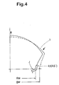
- the bead width BW of the mould 20 which is the axial distance between the bead shaping faces 4S' thereof and which corresponds to the axial distance between the axially outer surfaces 4S of the bead portions 4 of the demoulded vulcanised tyre, is set to be wider than the rim width RW of the standard wheel rim J by 15 to 30 mm.
- the belt cord tension in the tread edge portions is decreased, and the decrease in the ground contacting length during cornering is again controlled to improve cornering performance. Further, the lateral force variation can be further improved as shown in Table 2.
- the difference is less than 15 mm, the lateral force variation hardly improves. If the difference exceeds 30 mm, it becomes difficult to mount the tyre on the wheel rim.
- the standard wheel rim is a wheel rim officially approved for the tyre by, for example JATMA (Japan and Asia), T&RA (North America), ETRTO (Europe), STRO (Scandinavia) and the like.
- Table 2 is a test result showing the correlation between the lateral force variation LFV and the difference BW-RW between the bead width BW and rim width RW.
- tyres of size 120/60R17 (Rim size: MT3.5X17) were made changing the bead width BW, and the LFV was measured according to JASO-C607 under an inner pressure of 200 kPa and a tyre load of 137 kgf. Further, the rim mounting operation was also checked.
- the belt stretch during vulcanising the tyre is set in the specifically limited narrow range of from 6.0 to 7.0% at the tyre equator and gradually decreased from the tyre equator to the belt edges. Therefore, the lateral force variation and steering stability during straight running can be improved. Even if the ground contacting part shifts toward the tread edge during cornering, the ground contacting length is maintained and cornering performance can be improved.
- the present invention can be suitably applied to tyres for front wheels.
Landscapes
- Engineering & Computer Science (AREA)
- Mechanical Engineering (AREA)
- Tires In General (AREA)
- Heating, Cooling, Or Curing Plastics Or The Like In General (AREA)
- Tyre Moulding (AREA)
Abstract
Description
| Tyre | A1 | A2 | A3 | A4 | A5 |
| Belt stretch (%) | 4 | 5 | 6 | 7 | 8 |
| Belt ply width | |||||
| before vulcanisation | |||||
| inner ply (mm) | 115 | 115 | 115 | 115 | 115 |
| outer ply (mm) | 130 | 130 | 130 | 130 | 130 |
| after vulcanisation | |||||
| inner ply (mm) | 115 | 110 | 107 | 105 | 98 |
| outer ply (mm) | 130 | 129 | 126 | 123 | 115 |
| LFV | |||||
| average (kgf) | 4 | 3.8 | 3 | 2.9 | 2.8 |
| standard deviation (kgf) | 1.2 | 1.1 | 0.9 | 0.9 | 0.8 |
| Tyre | B1 | B2 | B3 | B4 |
| Belt stretch | ||||
| Sc (%) | 6 | 6 | 6 | 6 |
| Se (%) | 0.5 | 0.5 | 0.5 | 0.5 |
| Bead width BW (mm) | 89 | 101 | 119 | 134 |
| Rim width RW (mm) | 89 | 89 | 89 | 89 |
| BW-RW (mm) | 0 | 12 | 30 | 45 |
| Average LFV (kgf) | 3 | 2.7 | 2.5 | 2.5 |
| Rim mounting | good | good | poor | impossible |
Claims (8)
- A method of making a radial tyre for motorcycles, the radial tyre (1) comprising a carcass (6) extending between bead portions (4) through a tread portion (2) and sidewall portions (3), a belt (7) disposed radially outside the carcass (6) in the tread portion, and the belt (7) comprising two or three plies including two crossed breaker plies (7A,7B) of cords laid at angles of from 16 to 26 degrees with respect to the tyre equator, characterised by vulcanising the tyre (1) in a mould (20) causing a stretch (S) to the belt (7) during vulcanising the tyre, the stretch (S) being defined as (BD2/BD1-1)X100 where BD1 is the inside diameter of the belt before tyre vulcanisation, and BD2 is the inside diameter of the belt during tyre vulcanisation in the mould, the stretch (Sc)at the tyre equator (C) being in a range of from 6.0 to 7.0%, and the stretch (Sc) gradually decreases from the tyre equator (C) to the axial edges (BE) of the belt.
- A method according to claim 1, characterised in that the stretch (Se) at the belt edges is not more than 2.0%.
- A method according to claim 1 or 2, characterised in that the bead width (BW) of the mould (20) is wider than the rim width (RW) of a wheel rim for the tyre by 15 to 30 mm.
- A method according to claim 1, 2 or 3, characterised in that said two crossed breaker plies are a radially inner ply (7A) and a radially outer wider ply (7B) disposed on the inner ply (7A), the carcass (6) comprises a high-turnup ply having turnup portions (6b) extended radially outwardly to a radial height range of from hl-6% to h1+6%, where hi is a radial height of axial edges (BE) of the belt (7) measured from a bead base line (LB), a rubber sidewall (3G) is disposed axially outside the carcass (6) in each of the sidewall portions (3), and the sidewall (3G) extends radially outwardly beyond the axial edge (BE) of the radially outer breaker ply (7B), passing between the radially outer breaker ply (7B) and the carcass (6), and terminates at the axial edge (AE) of the radially inner breaker ply (7A).
- A radial tyre for motorcycles comprising a carcass (6) extending between bead portions (4) through a tread portion (2) and sidewall portions (3), a belt (7) disposed radially outside the carcass (6) in the tread portion (2) and composed of two or three plies (7A,7B) including two crossed breaker plies of cords laid at angles of from 16 to 26 degrees with respect to the tyre equator (C), characterised in that said belt is stretched during vulcanising the tyre in a mould (20) so that the stretch (Sc) at the tyre equator (C) is in a range of from 6.0 to 7.0%, and the stretch gradually decreases from the tyre equator (C) to the axial edges of the belt (BE), where the stretch is defined as (BD2/BD1-1)X100,BD1 being the inside diameter of the belt before vulcanisation, andBD2 being the inside diameter of the belt during vulcanisation.
- A radial tyre according to claim 5, characterised in that the stretch (Se) at the belt edges is not more than 2.0%.
- A radial tyre according to claim 5 or 6, characterised in that the bead width (BW) of the tyre is wider than the rim width (RW) of a wheel rim for the tyre by 15 to 30 mm.
- A radial tyre according to claim 5, 6 or 7, characterised in that said two crossed breaker plies are a radially inner ply (7A) and a radially outer wider ply (7B) disposed on the inner ply (7A), the carcass (6) comprises a high-turnup ply having turnup portions (6b) extended radially outwardly to a radial height in the range of from hl-6% to h1+6%, wherein hi is a radial height of axial edges (BE) of the belt (7) measured from a bead base line (LB), a rubber sidewall (3G) is disposed axially outside the carcass (6) in each of the sidewall portions (3), and the sidewall (3G) extends radially outwardly beyond the axial edge (BE) of the radially outer breaker ply (7B), passing between the radially outer breaker ply (7B) and the carcass (6), and terminates at the axial edge (AE) of the radially inner breaker ply (7A).
Applications Claiming Priority (2)
| Application Number | Priority Date | Filing Date | Title |
|---|---|---|---|
| JP31586199A JP3475135B2 (en) | 1999-11-05 | 1999-11-05 | Manufacturing method of radial tire for motorcycle |
| JP31586199 | 1999-11-05 |
Publications (2)
| Publication Number | Publication Date |
|---|---|
| EP1120231A1 true EP1120231A1 (en) | 2001-08-01 |
| EP1120231B1 EP1120231B1 (en) | 2004-06-16 |
Family
ID=18070484
Family Applications (1)
| Application Number | Title | Priority Date | Filing Date |
|---|---|---|---|
| EP00309714A Expired - Lifetime EP1120231B1 (en) | 1999-11-05 | 2000-11-02 | Radial tyre for motorcycle and method of making the same |
Country Status (4)
| Country | Link |
|---|---|
| US (1) | US6648040B1 (en) |
| EP (1) | EP1120231B1 (en) |
| JP (1) | JP3475135B2 (en) |
| DE (1) | DE60011562T2 (en) |
Cited By (5)
| Publication number | Priority date | Publication date | Assignee | Title |
|---|---|---|---|---|
| EP1825992A3 (en) * | 2006-02-22 | 2008-08-27 | Toyo Tire Rubber Co., Ltd. | Pneumatic tire and manufacturing method of the same |
| CN100584644C (en) * | 2006-08-28 | 2010-01-27 | 住友橡胶工业株式会社 | Band tire |
| CN107867120A (en) * | 2016-09-25 | 2018-04-03 | 固特异轮胎和橡胶公司 | Band tyre |
| CN109382946A (en) * | 2017-08-03 | 2019-02-26 | 住友橡胶工业株式会社 | The manufacturing method of the motorcycle tyre of rugged ground run |
| CN112384375A (en) * | 2018-07-11 | 2021-02-19 | 住友橡胶工业株式会社 | Heavy duty pneumatic tire and method of manufacturing the same |
Families Citing this family (2)
| Publication number | Priority date | Publication date | Assignee | Title |
|---|---|---|---|---|
| US20070013305A1 (en) | 2005-07-18 | 2007-01-18 | Wang Carl B | Thick film getter paste compositions with pre-hydrated desiccant for use in atmosphere control |
| JP5297503B2 (en) * | 2011-06-13 | 2013-09-25 | 住友ゴム工業株式会社 | Motorcycle tires |
Citations (4)
| Publication number | Priority date | Publication date | Assignee | Title |
|---|---|---|---|---|
| EP0502695A1 (en) * | 1991-03-05 | 1992-09-09 | Bridgestone Corporation | Pneumatic tires for two-wheeled vehicles |
| JPH0852737A (en) * | 1994-08-10 | 1996-02-27 | Sumitomo Rubber Ind Ltd | Manufacturing method of radial tire for motorcycle |
| JPH10193918A (en) * | 1997-01-08 | 1998-07-28 | Sumitomo Rubber Ind Ltd | Motorcycle tires |
| EP0863025A2 (en) * | 1997-03-07 | 1998-09-09 | Sumitomo Rubber Industries Limited | Motorcycle tyre and method of making the same |
Family Cites Families (8)
| Publication number | Priority date | Publication date | Assignee | Title |
|---|---|---|---|---|
| US3850219A (en) * | 1972-08-18 | 1974-11-26 | Uniroyal Inc | Steel-belted radial ply tires with o{20 {0 textile cap hand |
| DE2430495C3 (en) * | 1974-06-25 | 1979-02-22 | Continental Gummi-Werke Ag, 3000 Hannover | Method for manufacturing a belted tire |
| DE2510752C3 (en) * | 1975-03-12 | 1979-07-19 | Continental Gummi-Werke Ag, 3000 Hannover | Method of making a radial tire |
| FR2446193A1 (en) * | 1979-01-11 | 1980-08-08 | Kleber Colombes | TIRE, ESPECIALLY FOR AIRPLANES |
| JPS5839438A (en) * | 1981-09-02 | 1983-03-08 | Toyo Tire & Rubber Co Ltd | Manufacture of radial tire for passenger car |
| JPS62241704A (en) * | 1986-04-15 | 1987-10-22 | Bridgestone Corp | Belted tire |
| JPH0396403A (en) * | 1989-09-09 | 1991-04-22 | Sumitomo Rubber Ind Ltd | Pneumatic radial tire |
| US6065518A (en) * | 1995-08-01 | 2000-05-23 | Sumitomo Rubber Industries, Ltd. | Heavy duty pneumatic tire with high elongation steel belt cord |
-
1999
- 1999-11-05 JP JP31586199A patent/JP3475135B2/en not_active Expired - Fee Related
-
2000
- 2000-11-02 US US09/703,641 patent/US6648040B1/en not_active Expired - Fee Related
- 2000-11-02 DE DE60011562T patent/DE60011562T2/en not_active Expired - Lifetime
- 2000-11-02 EP EP00309714A patent/EP1120231B1/en not_active Expired - Lifetime
Patent Citations (4)
| Publication number | Priority date | Publication date | Assignee | Title |
|---|---|---|---|---|
| EP0502695A1 (en) * | 1991-03-05 | 1992-09-09 | Bridgestone Corporation | Pneumatic tires for two-wheeled vehicles |
| JPH0852737A (en) * | 1994-08-10 | 1996-02-27 | Sumitomo Rubber Ind Ltd | Manufacturing method of radial tire for motorcycle |
| JPH10193918A (en) * | 1997-01-08 | 1998-07-28 | Sumitomo Rubber Ind Ltd | Motorcycle tires |
| EP0863025A2 (en) * | 1997-03-07 | 1998-09-09 | Sumitomo Rubber Industries Limited | Motorcycle tyre and method of making the same |
Cited By (9)
| Publication number | Priority date | Publication date | Assignee | Title |
|---|---|---|---|---|
| EP1825992A3 (en) * | 2006-02-22 | 2008-08-27 | Toyo Tire Rubber Co., Ltd. | Pneumatic tire and manufacturing method of the same |
| EP2295230A1 (en) * | 2006-02-22 | 2011-03-16 | Toyo Tire & Rubber Co. Ltd. | Tire manufacturing method |
| CN100584644C (en) * | 2006-08-28 | 2010-01-27 | 住友橡胶工业株式会社 | Band tire |
| CN107867120A (en) * | 2016-09-25 | 2018-04-03 | 固特异轮胎和橡胶公司 | Band tyre |
| US10814674B2 (en) | 2016-09-25 | 2020-10-27 | The Goodyear Tire & Rubber Company | Heavy duty tire |
| CN109382946A (en) * | 2017-08-03 | 2019-02-26 | 住友橡胶工业株式会社 | The manufacturing method of the motorcycle tyre of rugged ground run |
| CN109382946B (en) * | 2017-08-03 | 2021-12-07 | 住友橡胶工业株式会社 | Method for manufacturing tyre of motorcycle for running on rough ground |
| CN112384375A (en) * | 2018-07-11 | 2021-02-19 | 住友橡胶工业株式会社 | Heavy duty pneumatic tire and method of manufacturing the same |
| EP3800069A4 (en) * | 2018-07-11 | 2022-04-13 | Sumitomo Rubber Industries, Ltd. | TIRE FOR HEAVY DUTY VEHICLES AND ASSOCIATED MANUFACTURING METHOD |
Also Published As
| Publication number | Publication date |
|---|---|
| US6648040B1 (en) | 2003-11-18 |
| DE60011562D1 (en) | 2004-07-22 |
| JP3475135B2 (en) | 2003-12-08 |
| JP2001130217A (en) | 2001-05-15 |
| DE60011562T2 (en) | 2005-08-18 |
| EP1120231B1 (en) | 2004-06-16 |
Similar Documents
| Publication | Publication Date | Title |
|---|---|---|
| US7036541B2 (en) | Pneumatic tire | |
| US5360044A (en) | Pneumatic radial tire with high cornering and steering stability | |
| US5200006A (en) | Pneumatic tire with uniform ground pressure at the tread face | |
| JP6946646B2 (en) | Motorcycle tires | |
| US8656970B2 (en) | Pneumatic radial tire for motorcycle | |
| RU2424122C1 (en) | Pair of tires for two-wheel motor bicycle | |
| US6305452B1 (en) | Pneumatic radical tire for passenger car with carcass ply cut-out zone | |
| EP1120231B1 (en) | Radial tyre for motorcycle and method of making the same | |
| CN100357119C (en) | Pneumatic tire | |
| JP2769040B2 (en) | Pneumatic radial tire for high-speed running | |
| JP3083862B2 (en) | Pneumatic tires for motorcycles | |
| US6250352B1 (en) | Motorcycle tire and method of making the same | |
| EP4005824B1 (en) | Motorcycle tire | |
| US5299612A (en) | Pneumatic radial tire with high cornering and steering stability | |
| US8695660B2 (en) | Pneumatic tire for motorcycle | |
| EP0661180A1 (en) | Passenger radial tyre | |
| JP2702583B2 (en) | Pneumatic radial tires for passenger cars | |
| JPH08216618A (en) | Pneumatic radial tires | |
| JPH06191226A (en) | Pneumatic tire | |
| CN116811483A (en) | Tyre for motor bicycle | |
| EP0858917B1 (en) | Pneumatic tyre | |
| EP3521059B1 (en) | Motorcycle tire | |
| EP0779163B1 (en) | Motorcycle tyre | |
| JPH05604A (en) | Radial tires for motorcycles | |
| JPH11321216A (en) | Heavy duty tire |
Legal Events
| Date | Code | Title | Description |
|---|---|---|---|
| PUAI | Public reference made under article 153(3) epc to a published international application that has entered the european phase |
Free format text: ORIGINAL CODE: 0009012 |
|
| AK | Designated contracting states |
Kind code of ref document: A1 Designated state(s): DE FR GB |
|
| AX | Request for extension of the european patent |
Free format text: AL;LT;LV;MK;RO;SI |
|
| 17P | Request for examination filed |
Effective date: 20020109 |
|
| AKX | Designation fees paid |
Free format text: DE FR GB |
|
| 17Q | First examination report despatched |
Effective date: 20030123 |
|
| GRAP | Despatch of communication of intention to grant a patent |
Free format text: ORIGINAL CODE: EPIDOSNIGR1 |
|
| GRAS | Grant fee paid |
Free format text: ORIGINAL CODE: EPIDOSNIGR3 |
|
| GRAA | (expected) grant |
Free format text: ORIGINAL CODE: 0009210 |
|
| AK | Designated contracting states |
Kind code of ref document: B1 Designated state(s): DE FR GB |
|
| REG | Reference to a national code |
Ref country code: GB Ref legal event code: FG4D |
|
| REF | Corresponds to: |
Ref document number: 60011562 Country of ref document: DE Date of ref document: 20040722 Kind code of ref document: P |
|
| ET | Fr: translation filed | ||
| PLBE | No opposition filed within time limit |
Free format text: ORIGINAL CODE: 0009261 |
|
| STAA | Information on the status of an ep patent application or granted ep patent |
Free format text: STATUS: NO OPPOSITION FILED WITHIN TIME LIMIT |
|
| 26N | No opposition filed |
Effective date: 20050317 |
|
| PGFP | Annual fee paid to national office [announced via postgrant information from national office to epo] |
Ref country code: DE Payment date: 20141029 Year of fee payment: 15 Ref country code: FR Payment date: 20141110 Year of fee payment: 15 Ref country code: GB Payment date: 20141029 Year of fee payment: 15 |
|
| REG | Reference to a national code |
Ref country code: DE Ref legal event code: R119 Ref document number: 60011562 Country of ref document: DE |
|
| GBPC | Gb: european patent ceased through non-payment of renewal fee |
Effective date: 20151102 |
|
| REG | Reference to a national code |
Ref country code: FR Ref legal event code: ST Effective date: 20160729 |
|
| PG25 | Lapsed in a contracting state [announced via postgrant information from national office to epo] |
Ref country code: DE Free format text: LAPSE BECAUSE OF NON-PAYMENT OF DUE FEES Effective date: 20160601 Ref country code: GB Free format text: LAPSE BECAUSE OF NON-PAYMENT OF DUE FEES Effective date: 20151102 |
|
| PG25 | Lapsed in a contracting state [announced via postgrant information from national office to epo] |
Ref country code: FR Free format text: LAPSE BECAUSE OF NON-PAYMENT OF DUE FEES Effective date: 20151130 |