EP1120169B1 - Ultraschallsonde - Google Patents
Ultraschallsonde Download PDFInfo
- Publication number
- EP1120169B1 EP1120169B1 EP00204333A EP00204333A EP1120169B1 EP 1120169 B1 EP1120169 B1 EP 1120169B1 EP 00204333 A EP00204333 A EP 00204333A EP 00204333 A EP00204333 A EP 00204333A EP 1120169 B1 EP1120169 B1 EP 1120169B1
- Authority
- EP
- European Patent Office
- Prior art keywords
- transducer elements
- array
- support member
- pulse
- ultrasound probe
- Prior art date
- Legal status (The legal status is an assumption and is not a legal conclusion. Google has not performed a legal analysis and makes no representation as to the accuracy of the status listed.)
- Expired - Lifetime
Links
- 238000002604 ultrasonography Methods 0.000 title claims abstract description 24
- 239000000523 sample Substances 0.000 title claims abstract description 17
- 238000003491 array Methods 0.000 claims abstract description 14
- 238000012285 ultrasound imaging Methods 0.000 claims abstract description 7
- 230000002708 enhancing effect Effects 0.000 claims abstract description 5
- 239000000463 material Substances 0.000 claims description 6
- 239000003094 microcapsule Substances 0.000 description 11
- 238000003384 imaging method Methods 0.000 description 7
- 239000003795 chemical substances by application Substances 0.000 description 5
- 238000010276 construction Methods 0.000 description 3
- 238000013461 design Methods 0.000 description 3
- 238000002474 experimental method Methods 0.000 description 3
- 239000000835 fiber Substances 0.000 description 3
- 238000001208 nuclear magnetic resonance pulse sequence Methods 0.000 description 3
- 239000011295 pitch Substances 0.000 description 3
- 239000004593 Epoxy Substances 0.000 description 2
- 230000000052 comparative effect Effects 0.000 description 2
- 230000000694 effects Effects 0.000 description 2
- 239000012216 imaging agent Substances 0.000 description 2
- 238000000034 method Methods 0.000 description 2
- 238000012986 modification Methods 0.000 description 2
- 230000004048 modification Effects 0.000 description 2
- 235000014036 Castanea Nutrition 0.000 description 1
- 241001070941 Castanea Species 0.000 description 1
- 102000007562 Serum Albumin Human genes 0.000 description 1
- 108010071390 Serum Albumin Proteins 0.000 description 1
- 238000004458 analytical method Methods 0.000 description 1
- 239000002872 contrast media Substances 0.000 description 1
- 238000001514 detection method Methods 0.000 description 1
- 238000010586 diagram Methods 0.000 description 1
- 238000009826 distribution Methods 0.000 description 1
- 238000001035 drying Methods 0.000 description 1
- 239000002961 echo contrast media Substances 0.000 description 1
- 230000000763 evoking effect Effects 0.000 description 1
- 238000005259 measurement Methods 0.000 description 1
- 239000011859 microparticle Substances 0.000 description 1
- 239000004005 microsphere Substances 0.000 description 1
- ORQBXQOJMQIAOY-UHFFFAOYSA-N nobelium Chemical compound [No] ORQBXQOJMQIAOY-UHFFFAOYSA-N 0.000 description 1
- 230000002688 persistence Effects 0.000 description 1
- 238000012545 processing Methods 0.000 description 1
- 230000005855 radiation Effects 0.000 description 1
- 238000000926 separation method Methods 0.000 description 1
- 230000001360 synchronised effect Effects 0.000 description 1
- 238000012360 testing method Methods 0.000 description 1
- 230000001960 triggered effect Effects 0.000 description 1
- XLYOFNOQVPJJNP-UHFFFAOYSA-N water Substances O XLYOFNOQVPJJNP-UHFFFAOYSA-N 0.000 description 1
Images


Classifications
-
- B—PERFORMING OPERATIONS; TRANSPORTING
- B06—GENERATING OR TRANSMITTING MECHANICAL VIBRATIONS IN GENERAL
- B06B—METHODS OR APPARATUS FOR GENERATING OR TRANSMITTING MECHANICAL VIBRATIONS OF INFRASONIC, SONIC, OR ULTRASONIC FREQUENCY, e.g. FOR PERFORMING MECHANICAL WORK IN GENERAL
- B06B1/00—Methods or apparatus for generating mechanical vibrations of infrasonic, sonic, or ultrasonic frequency
- B06B1/02—Methods or apparatus for generating mechanical vibrations of infrasonic, sonic, or ultrasonic frequency making use of electrical energy
- B06B1/06—Methods or apparatus for generating mechanical vibrations of infrasonic, sonic, or ultrasonic frequency making use of electrical energy operating with piezoelectric effect or with electrostriction
- B06B1/0607—Methods or apparatus for generating mechanical vibrations of infrasonic, sonic, or ultrasonic frequency making use of electrical energy operating with piezoelectric effect or with electrostriction using multiple elements
- B06B1/0611—Methods or apparatus for generating mechanical vibrations of infrasonic, sonic, or ultrasonic frequency making use of electrical energy operating with piezoelectric effect or with electrostriction using multiple elements in a pile
- B06B1/0614—Methods or apparatus for generating mechanical vibrations of infrasonic, sonic, or ultrasonic frequency making use of electrical energy operating with piezoelectric effect or with electrostriction using multiple elements in a pile for generating several frequencies
Definitions
- the invention relates to an ultrasound probe for ultrasound imaging, more in particular to ultrasound imaging using contrast enhancing agents and comprising two interleaved arrays of transducer elements, each of said arrays having a longitudinal dimension along which said transducer elements are placed side by side, a first one of said interleaved arrays comprising transducer elements having a lower center frequency and a second one of said interleaved arrays comprising transducer elements having a higher center frequency.
- Such a probe is described in international patent application no. WO99/35967 and is used for ultrasound imaging and more particularly in a multipulse and enhancement strategy for ultrasound imaging of an object containing an ultrasound contrast enhancing imaging agent.
- Ultrasound contrast agents can be introduced into the body to reflect or absorb ultrasound energy, or to resonate when exposed to such energy, and thereby provide an enhanced image of a part of the body.
- contrast agents in the form of hollow microcapsules, are given in Japanese patent applications nos. 508032/1992 and 509745/1994 and in PCT/GB95/02673 (WO96/15814). Such agents are injected into the patient's bloodstream and then the patient is subjected to ultrasound radiation.
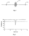
- An ultrasound sequence may comprise a multiple sequence comprising a first pulse burst at a first frequency and low amplitude followed by a second pulse burst at a second frequency and relatively higher amplitude. This second pulse is of sufficient magnitude to induce power enhanced scattering, as defined, in a region of interest. This is then further followed by a third pulse burst of a third frequency and lower amplitude.
- Power enhanced scattering is defined as providing an acoustic pulse at an amplitude at least sufficient to cause a change in the acoustic properties of the region of interest to, for example, cause bubbles to be released from the microcapsules.
- a known method of producing an ultrasound image of an object containing an ultrasonic contrast imaging agent comprises subjecting the object to a first pulse burst of a first sequency and first power, subjecting the object to a second pulse burst of a second frequency in combination with a second power for optimal bubble release and subjecting the object to a third pulse burst of a third frequency and third power, obtaining a first image of the object as a result of the first pulse burst, obtaining a second image of the object as a result of the third pulse burst and comparing the first and second images to obtain a final enhanced image.
- said first power is a low power relative to said second power which is a high power and said third power is a low power relative to said second power.
- the first and third pulse bursts are at a frequency higher than that of the second pulse bursts, but alternatively the first and third pulse burst may be at a frequency lower than that of the second pulse burst.
- the first and third pulse bursts are identical or have a defined and known relationship.
- the first and third pulse bursts comprise a relatively lower number of cycles than the second pulse burst.
- the first and third pulse bursts may comprise a single cycle.
- the second pulse burst comprises a plurality of cycles.
- the time between the first and third pulse bursts is less than 100 ⁇ s.
- the third pulse birst may be combined with or overlap with the second pulse bursts. Any image pulse obtained from the third pulse burst can be filtered out from any interference from the second pulse bursts by virtue of the difference in frequencies.
- a first image is obtained during the first pulse burst and a second image is obtained during the third pulse burst.
- the second higher amplitude pulse burst comprises a release burst for release of bubbles from a suitable agent such as Quantison.
- Suitable microcapsules include those disclosed as "QUANTISON”TM microcapsules by Andaris Limited, and described in WO92/18164 (US 5,518,709), WO94/08627 and WO96/15814 (USSN 08/676,344 filed 19 July 1996).
- the microcapsules are made by spare-drying a solution of serum albumin to form hollow microcapsules generallly of diameter 1 to 10 ⁇ m; for example 90% may have a diameter of 1.0 to 9.0 ⁇ m or 1 to 6.0 ⁇ m, as measured in a Coulter Counter Multmizer II.
- any gas containing microcapsule, microsphere or microparticle which releases the gas on irridation with a non-physiologically harmful dose of ultrasound may be used in the methods of the invention.
- the first and second images obtained during the first and third pulse bursts are compared with each other to provide a combined improved image, for example by subtractive decorrelation.
- an exemplary multipulse sequence comprises a first pulse burst 10 at relatively low amplitude and a third pulse burst 14 also at relatively low amplitude, both pulse bursts being at relatively high frequency, e.g. 5 MHz and relatively fewer cycles compared to the second pulse burst.
- a preferred embodiment comprises a pulse that is shaped for maximum resolution on imaging. In the specific embodiment shown only one cycle is used.
- the first and third pulse bursts are preferably identical but they may have a defined relationship and in this case the processing circuitry will compensate to provide a comparative image.
- a second pulse burst having a power selected for optimal bubble release.
- the second pulse burst is a relatively low frequency (e.g. 2 MHz) pulse burst having a greater amplitude.
- the second pulse burst also preferably has a greater number of cycles than the first pulse burst.
- the second pulse burst comprises a pulse burst that is optimal for gas bubble release. In a specific embodiment the pulse burst has four or more cycles.
- the second pulse burst could, however, be of higher frequency, in which case the power (amplitude) of the second pulse burst could for some microcapsules be lower. What is required is a pulse burst of such frequency and power for the microcapsules that bubble release occurs and this will depend on a number of factors, including the type of microcapsule, which factors will be known to the person skilled in the art.
- two images are taken, one on each of the first and third pulse bursts, and the second pulse burst is used to induce Power Enhanced Scattering (PES) of bubbles from microcapsules contained in the region of interest.
- PES Power Enhanced Scattering
- the image taken during the first pulse burst is compared with that in the third pulse burst to obtain an enhanced comparative image.
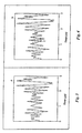
- Figure 2 shows the comparison, in this case a substractive decorrelation obtained from the pulse sequence of Figure 1 with thresholding of the data (from Figures 3 and 4) using an 80% correlation level.
- the experiment is set up to simulate a triggered M-mode with the test object being a single fibre containing QUANTISON.
- Figure 3 represents the result of the two Radio-Frequency (RF) imaging pulses without the high amplitude burst, in which no PES and no free air bubbles are detected.
- RF Radio-Frequency
- Figure 4 shows the result when the second burst, in between the image pulses, is switched on.
- the second imaging pulse (the third pulse burst) detects the generated free air bubbles.
- the change in amplitude is minimal, due to the high scattering surrounding material.
- these minimal changes can be accurately detected.
- the complete pulse sequence should be carried out within as short a period of time as is reasonably practical, bearing in mind the persistence of the evoked bubble release, acoustic velocities and depth of region of interest.
- the total time period is 100 ⁇ s.
- first/third pulses can be 3 MHz and the second 500 kHz or the first/third pulses can be 5 MHz and the second 1 MHz.
- the power of the first (10) and third (14) pulse bursts should be such as not to induce any power enhanced scattering (release of bubbles) from the QUANTISON.
- the power of the first and thrid pulses should preferably not be higher than 0.1 MPa.
- the power of the centre (second) pulse burst must be such as to produce power enhanced scattering as defined, and should preferably be above 0.6 MPa for QUANTISON.
- the frequency of the second pulse burst 12 is different from that of the first/third pulse bursts, it is convenient to filter out any residual effects from the second pulse burst when imaging.
- the total sequence time which could be as short as possible, will have to be a minimum of 100 ⁇ s for an object depth of 75 mm for most practical purposes. The total time could possibly be shorter if the imaged object was at a shallower depth.
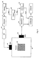
- a 1 MHz single element transducer 50 (Panametrics, Waltham, MA, USA) with a focus at 7.5 cm is mounted in a water bath 52 filled with Isoton® II (Coulter Diagnostics) and used as the high power transmitter.
- a 5 MHz single element broadband transducer 54 Perpendicular to the acoustical beam of this transducer a 5 MHz single element broadband transducer 54 (Panametrics, Waltham, MA, USA), with a focus at 7.5 cm, is mounted and used to probe the target 56 positioned in the center of the waterbath (transmit/receive).
- the 1 MHz high power sinusoidal signal of 10 cycles with a peak-peak acoustical pressure of 1.8 MPa and repetition rate of 1 Hz is generated by a pulse generator 58 (PM5716, Philips) a Wavetek signal generator 60 and a linear power amplifier 62 model A-500 (ENI, NY).
- a short 5 MHz pulse is generated and received by apulser/receiver 64 (5052 PR, Panametrics, Waltham, MA, USA).
- the received signal can be amplified from +40 dB to -40 dB in steps of 2 dB.
- the amplified signal is filtered with a low pass Chebychev filter and digitized by a Lecroy 9400A (Lecroy, Chestnut Ridge, NY, USA) digital oscilloscope (100 MHz, 8 bits).
- the pulser/receiver is synchronized by a pulse generator 66 (PM 5712, Philips) with a delay of 0.5 ms relative to the 1 MHz transmitted signal.
- the output signals are recorded over time windows of 10 ⁇ s and transferred to a personal computer (Compaq 386/20e) for further analysis.
- the third pulse 12 could be combined within the second pulse since the scattered signal from the third pulse can be filtered out.
- first and third pulses for example for velocity measurement, it is possible for the first and third pulses to be of relatively low frequency and for the second pulse to be of relatively higher frequency, i.e. the opposite of the first example.
- the first transducer element 610 is sensitive to low frequency and the second 620 is sensitive to high frequency. Both elements may be of the piezoelectric type.
- the low frequency transducer (type 610) is used for sending, the other one 620 can be used for both receiving alone and for transmitting and receiving for imaging.
- the two transducer types (610, 620) can be merged as shown by interleaving the two types, thereby defining e.g. the odd elements as type 1 and the even elements as type 2. Other distributions are also possible.
- Type 2 transducer can be used for imaging in both the fundamental as well as the second harmonic mode.
- a preferred embodiment of an ultrasound probe according to the invention in which a single piece of backing material is connected to all second transducer elements has an airgap present between a backside of said first transducer elements and said backing material.
- an amplitude of the ultrasound generated by the first transducer elements is larger than it would be when said first transducer elements would have been in contact with a backing.
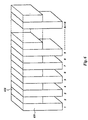
- Figure 7A and 7B show a first support element 101 in the form of a rectangular box without a bottom and without a top.
- a number of transducer elements 102a, 102b, ..., 102f, ... is provided and fixedly connected to the support element 101.
- Each of the transducer elements is provided with a corresponding electrical contact 103a, ...,103f, ....
- the number of transducer elements 102 may be 48.
- the center frequency of each of the elements 102 is relatively low, for example 900 kHz.
- the transducer elements 102 are placed side by side, along a longitudinal direction of the first support element 101.
- a separation between subsequent first transducer elements is of the order of 250 ⁇ m, and the pitch of the array is 0.5 mm.
- Each individual transducer element 102 has its own individual connected ground-contact, for example by using flexprints 103 connected with conductive epoxy to the electrode of the transducer elements.
- FIGS 8A en 8B show the second array mounted on a second support element 110 and comprising transducer elements 111a, 111b, ... is provided with electrical contacts 112a, 112b, ... each of the transducer elements 111 is in contact with a backing 113.
- the backing 113 fills the entire innerspace of the second support element 110.
- Each of the transducer elements 111 is provided with suitable matching layers 114. The dimensions of the transducer elements 111 and of the matching layers 114 are such that the center frequency and the bandwidth of the transducer elements 111 comprise the second, third and fourth harmonic of the center frequency of the transducer elements 102 of the first array.
- each individual element has its own individually connected ground-contact, for example by using flexprints connected with conductive epoxy to the electrode of the transducer elements 111. It is also possible for the array to have one ground contact shared by all elements. Nevertheless in that case each element also has a contact for the second electrical contact for connection to a transmitting or receiving device.
- the pitches of the first array and of the second array are the same and their dimensions of the transducer elements 102 and 111 in the longitudinal direction of the arrays are such that the elements 111 fit neatly in the spaces 107 between the transducer elements 102 and the transducer elements 102 fit within the spaces between the transducer elements 111.
- Figures 9A, 9B and 10 show the ultrasound probe after the first and the second support elements have been integrated.
- a bottom opening 104 of the first support elements 101 has been used for the passage of the second support element 110 into the inside of the first support element 101.
- the dimension b (see Figure 8A) of the second support element is at most as large as an inner dimension a (see Figure 7B) of first support element 101.
- the elements 102 and the elements III form a single transmitting and receiving surface for ultrasound waves in a fully interleaved way of two separate arrays.
- the backing 113 for the element 111 of the second array does not fill the space between itself and a backside 114 of the transducer elements 102 of the first array.
- the transducer elements 102 of the first array have a relatively low center frequency of for example 900 kHz.
- the bandwidth of the first array can be approximately 40 to 50 %, which means that the bandwidth expressed in megahertz is about 40 to 50 % of the centre frequency of 0.9 MHz. With respect to the first array the bandwidth is not or not very much important.
- the transducer elements 111 of the second array it is important that those elements are able to detect a higher harmonic, such as a second, a third or a fourth harmonic, of the center frequency used in the first array. This can for example be done by designing the thickness and the matching layers of the transducer elements 111 such that the center frequency is 2.8 MHz and the bandwidth is about 80%.
- the design of such transducer elements and corresponding matching layers is no problem for a person skilled in the art and is not part of the present invention as such.
Landscapes
- Engineering & Computer Science (AREA)
- Mechanical Engineering (AREA)
- Ultra Sonic Daignosis Equipment (AREA)
- Transducers For Ultrasonic Waves (AREA)
- Surgical Instruments (AREA)
- Apparatuses For Generation Of Mechanical Vibrations (AREA)
- Investigating Or Analyzing Materials By The Use Of Ultrasonic Waves (AREA)
Claims (7)
- Ultraschallsonde für die Ultraschallabbildung unter Verwendung von kontrastverbessernden Agensen bzw. Mitteln, die zwei ineinander greifende Anordnungen von Wandlerelementen aufweist, wobei jede der Anordnungen eine Längsabmessung besitzt, entlang der die Wandlerelemente Seite an Seite platziert sind, wobei eine erste der ineinander greifenden Anordnungen Wandlerelemente mit einer niedrigeren Mittelfrequenz besitzt, und eine zweite der ineinander greifenden Anordnungen Wandlerelemente mit einer höheren Mittelfrequenz besitzt, dadurch gekennzeichnet, dass die Wandlerelemente der ersten ineinander greifenden Anordnung an einem ersten hohlen Tragglied vorgesehen sind, wobei die Wandlerelemente der zweiten ineinander greifenden Anordnung an einem zweiten Tragglied vorgesehen sind, wobei das zweite Tragglied in das erste Tragglied passt, wobei die Länge der Wandlerelemente der ersten Anordnung in einer Ebene der Anordnung und in einer Richtung im Wesentlichen senkrecht zu der Längsabmessung größer ist als die entsprechende Länge der Elemente der zweiten Anordnung, und wobei die entsprechende Länge der Wandlerelemente der zweiten Anordnung nicht größer als die entsprechend Innenabmessung des ersten hohlen Traggliedes ist.
- Ultraschallsonde nach Anspruch 1, wobei das erste hohle Tragglied mit elektrischen Verbindungen für die ersten Wandlerelemente versehen ist, und wobei das zweite Tragglied mit elektrischen Verbindungen für die zweiten Wandlerelemente versehen ist.
- Ultraschallsonde nach Anspruch 1, wobei das erste hohle Tragglied eine erste Öffnung aufweist, die durch die ersten Wandlerelemente abgedeckt ist, und wobei wenigstens eine zweite Öffnung mit ausreichenden Querschnittsabmessungen vorgesehen ist, um einen Zugriff auf das Innere des ersten hohlen Traggliedes durch das zweite Tragglied, das mit den zweiten Wandlerelementen versehen ist, zu erlauben.
- Ultraschallsonde nach Anspruch 1, wobei jedes der zweiten Wandlerelemente mit einem Backing bzw. einer Unterstützung versehen ist.
- Ultraschallsonde nach Anspruch 4, wobei Räume zwischen den zweiten Wandlerelementen mit Backing bzw. Stützmaterial gefüllt sind.
- Ultraschallsonde nach Anspruch 5, wobei ein einzelnes Stück aus Stützmaterial mit allen zweiten Wandlerelementen verbunden ist.
- Ultraschallsonde nach Anspruch 4 oder 5, wobei ein Luftspalt zwischen einer Rückseite der ersten Wandlerelemente und dem Stützmaterial vorgesehen ist.
Applications Claiming Priority (2)
| Application Number | Priority Date | Filing Date | Title |
|---|---|---|---|
| NL1014175 | 2000-01-25 | ||
| NL1014175A NL1014175C2 (nl) | 2000-01-25 | 2000-01-25 | Ultrageluid probe. |
Publications (2)
| Publication Number | Publication Date |
|---|---|
| EP1120169A1 EP1120169A1 (de) | 2001-08-01 |
| EP1120169B1 true EP1120169B1 (de) | 2006-03-22 |
Family
ID=19770662
Family Applications (1)
| Application Number | Title | Priority Date | Filing Date |
|---|---|---|---|
| EP00204333A Expired - Lifetime EP1120169B1 (de) | 2000-01-25 | 2000-12-05 | Ultraschallsonde |
Country Status (7)
| Country | Link |
|---|---|
| US (1) | US6575909B2 (de) |
| EP (1) | EP1120169B1 (de) |
| JP (1) | JP4623537B2 (de) |
| AT (1) | ATE320863T1 (de) |
| DE (1) | DE60026782T2 (de) |
| NL (1) | NL1014175C2 (de) |
| NO (1) | NO20010428L (de) |
Families Citing this family (6)
| Publication number | Priority date | Publication date | Assignee | Title |
|---|---|---|---|---|
| US7862512B2 (en) * | 2005-08-29 | 2011-01-04 | Unex Corporation | Blood vessel endothelium function evaluating apparatus provided with an electronic control device |
| GB2457240B (en) * | 2008-02-05 | 2013-04-10 | Fujitsu Ltd | Ultrasound probe device and method of operation |
| WO2013032946A1 (en) * | 2011-08-26 | 2013-03-07 | University Of Pittsburgh -Of The Commonwealth System Of Higher Education | Contrast assisted intravascular ultrasound imaging |
| JP6210679B2 (ja) * | 2012-12-12 | 2017-10-11 | オリンパス株式会社 | 半導体装置接続構造、超音波モジュールおよび超音波モジュールを搭載した超音波内視鏡システム |
| CN114146888B (zh) * | 2021-11-04 | 2022-08-30 | 深圳市智佐生物科技有限公司 | 一种基于多频点谐振的宽带超声换能器阵列 |
| WO2025204808A1 (ja) * | 2024-03-28 | 2025-10-02 | ヤマハファインテック株式会社 | 超音波送信器、超音波送受信ユニットおよび超音波検査装置 |
Family Cites Families (14)
| Publication number | Priority date | Publication date | Assignee | Title |
|---|---|---|---|---|
| JPS58155844A (ja) * | 1982-03-10 | 1983-09-16 | 松下電器産業株式会社 | 超音波探触子 |
| US5099459A (en) * | 1990-04-05 | 1992-03-24 | General Electric Company | Phased array ultrosonic transducer including different sized phezoelectric segments |
| GB9107628D0 (en) | 1991-04-10 | 1991-05-29 | Moonbrook Limited | Preparation of diagnostic agents |
| AU671423B2 (en) | 1991-11-06 | 1996-08-29 | Allan James Yeomans | Radiant energy collecting apparatus |
| GB9221329D0 (en) | 1992-10-10 | 1992-11-25 | Delta Biotechnology Ltd | Preparation of further diagnostic agents |
| DE4302537C1 (de) * | 1993-01-29 | 1994-04-28 | Siemens Ag | Therapiegerät zur Ortung und Behandlung einer Zone im Körper eines Lebewesens mit akustischen Wellen |
| US5420429A (en) * | 1993-10-08 | 1995-05-30 | General Electric Company | Multilayer transducer array |
| GB9423419D0 (en) | 1994-11-19 | 1995-01-11 | Andaris Ltd | Preparation of hollow microcapsules |
| US5509417A (en) * | 1994-12-19 | 1996-04-23 | Hewlett Packard Company | Method and apparatus for phased array coupling ultrasonic energy into an acoustic waveguide wire |
| JP3510025B2 (ja) * | 1995-11-10 | 2004-03-22 | ジーイー横河メディカルシステム株式会社 | 超音波撮像装置 |
| US5906580A (en) * | 1997-05-05 | 1999-05-25 | Creare Inc. | Ultrasound system and method of administering ultrasound including a plurality of multi-layer transducer elements |
| GB9800813D0 (en) | 1998-01-16 | 1998-03-11 | Andaris Ltd | Improved ultrasound contrast imaging method and apparatus |
| US6117082A (en) * | 1999-03-31 | 2000-09-12 | Acuson Corporation | Medical diagnostic ultrasound imaging system and method with fractional harmonic seed signal |
| JP3660903B2 (ja) * | 2001-12-11 | 2005-06-15 | アロカ株式会社 | 超音波探触子及び超音波診断装置 |
-
2000
- 2000-01-25 NL NL1014175A patent/NL1014175C2/nl not_active IP Right Cessation
- 2000-12-05 DE DE60026782T patent/DE60026782T2/de not_active Expired - Lifetime
- 2000-12-05 AT AT00204333T patent/ATE320863T1/de not_active IP Right Cessation
- 2000-12-05 EP EP00204333A patent/EP1120169B1/de not_active Expired - Lifetime
-
2001
- 2001-01-09 US US09/757,867 patent/US6575909B2/en not_active Expired - Lifetime
- 2001-01-24 NO NO20010428A patent/NO20010428L/no unknown
- 2001-01-24 JP JP2001015979A patent/JP4623537B2/ja not_active Expired - Fee Related
Also Published As
| Publication number | Publication date |
|---|---|
| JP4623537B2 (ja) | 2011-02-02 |
| NO20010428D0 (no) | 2001-01-24 |
| DE60026782D1 (de) | 2006-05-11 |
| NO20010428L (no) | 2001-07-26 |
| DE60026782T2 (de) | 2007-01-11 |
| EP1120169A1 (de) | 2001-08-01 |
| ATE320863T1 (de) | 2006-04-15 |
| US6575909B2 (en) | 2003-06-10 |
| JP2001258885A (ja) | 2001-09-25 |
| NL1014175C2 (nl) | 2001-07-26 |
| US20010021809A1 (en) | 2001-09-13 |
Similar Documents
| Publication | Publication Date | Title |
|---|---|---|
| US6726629B1 (en) | Ultrasound contrast imaging | |
| US6984209B2 (en) | Harmonic motion imaging | |
| US5903516A (en) | Acoustic force generator for detection, imaging and information transmission using the beat signal of multiple intersecting sonic beams | |
| US5921928A (en) | Acoustic force generation by amplitude modulating a sonic beam | |
| US5833615A (en) | Excitation enhanced ultrasound system | |
| CA2129946C (en) | Broadband phased array transducer design with frequency controlled two dimension capability and methods for manufacture thereof | |
| US6752762B1 (en) | Method and apparatus for ultrasound contrast imaging | |
| US4963782A (en) | Multifrequency composite ultrasonic transducer system | |
| US6322512B1 (en) | Ultrasound contrast imaging | |
| CN110997165B (zh) | 电容式微机械超声换能器(cmut)设备和控制方法 | |
| Azuma et al. | Dual-frequency ultrasound imaging and therapeutic bilaminar array using frequency selective isolation layer | |
| Gross et al. | A cMUT probe for ultrasound-guided focused ultrasound targeted therapy | |
| Boulmé et al. | A capacitive micromachined ultrasonic transducer probe for assessment of cortical bone | |
| EP1120169B1 (de) | Ultraschallsonde | |
| CN103069844A (zh) | 超声波探头和使用它的超声波诊断装置 | |
| Jiang et al. | Passive cavitation detection with a needle hydrophone array | |
| Cathignol et al. | Electronic beam steering of shock waves | |
| CN112403873B (zh) | 一种堆叠式超声换能器 | |
| Schafer et al. | Development of a high intensity focused ultrasound (HIFU) hydrophone system | |
| Kreider et al. | Beamwidth measurement of individual lithotripter shock waves | |
| Kluiwstra et al. | Therapeutic ultrasound phased arrays: practical consideration and design strategies | |
| Mattesini | Development of methods and electronic circuits for ultrasound imaging based on innovative probes | |
| Oh et al. | Fabrication of Wafer-Bonded 2D CMUT Array with Glass-Filled Trenches | |
| Shiozaki et al. | 1Pa5-6 Ultrasound Imaging of Cavitation Bubbles by Triplet Pulse Sequence with Reduction of Therapeutic Ultrasound Noise | |
| Kilinc et al. | CMUT-Based Focused Ultrasound Transmit Array for Blood-Brain Barrier Opening in Small Animal Models |
Legal Events
| Date | Code | Title | Description |
|---|---|---|---|
| PUAI | Public reference made under article 153(3) epc to a published international application that has entered the european phase |
Free format text: ORIGINAL CODE: 0009012 |
|
| AK | Designated contracting states |
Kind code of ref document: A1 Designated state(s): AT BE CH CY DE DK ES FI FR GB GR IE IT LI LU MC NL PT SE TR |
|
| AX | Request for extension of the european patent |
Free format text: AL;LT;LV;MK;RO;SI |
|
| 17P | Request for examination filed |
Effective date: 20020121 |
|
| AKX | Designation fees paid |
Free format text: AT BE CH CY DE DK ES FI FR GB GR IE IT LI LU MC NL PT SE TR |
|
| GRAP | Despatch of communication of intention to grant a patent |
Free format text: ORIGINAL CODE: EPIDOSNIGR1 |
|
| GRAS | Grant fee paid |
Free format text: ORIGINAL CODE: EPIDOSNIGR3 |
|
| GRAA | (expected) grant |
Free format text: ORIGINAL CODE: 0009210 |
|
| AK | Designated contracting states |
Kind code of ref document: B1 Designated state(s): AT BE CH CY DE DK ES FI FR GB GR IE IT LI LU MC NL PT SE TR |
|
| PG25 | Lapsed in a contracting state [announced via postgrant information from national office to epo] |
Ref country code: IT Free format text: LAPSE BECAUSE OF FAILURE TO SUBMIT A TRANSLATION OF THE DESCRIPTION OR TO PAY THE FEE WITHIN THE PRESCRIBED TIME-LIMIT;WARNING: LAPSES OF ITALIAN PATENTS WITH EFFECTIVE DATE BEFORE 2007 MAY HAVE OCCURRED AT ANY TIME BEFORE 2007. THE CORRECT EFFECTIVE DATE MAY BE DIFFERENT FROM THE ONE RECORDED. Effective date: 20060322 Ref country code: BE Free format text: LAPSE BECAUSE OF FAILURE TO SUBMIT A TRANSLATION OF THE DESCRIPTION OR TO PAY THE FEE WITHIN THE PRESCRIBED TIME-LIMIT Effective date: 20060322 Ref country code: AT Free format text: LAPSE BECAUSE OF FAILURE TO SUBMIT A TRANSLATION OF THE DESCRIPTION OR TO PAY THE FEE WITHIN THE PRESCRIBED TIME-LIMIT Effective date: 20060322 Ref country code: CH Free format text: LAPSE BECAUSE OF FAILURE TO SUBMIT A TRANSLATION OF THE DESCRIPTION OR TO PAY THE FEE WITHIN THE PRESCRIBED TIME-LIMIT Effective date: 20060322 Ref country code: LI Free format text: LAPSE BECAUSE OF FAILURE TO SUBMIT A TRANSLATION OF THE DESCRIPTION OR TO PAY THE FEE WITHIN THE PRESCRIBED TIME-LIMIT Effective date: 20060322 |
|
| REG | Reference to a national code |
Ref country code: GB Ref legal event code: FG4D |
|
| REG | Reference to a national code |
Ref country code: CH Ref legal event code: EP |
|
| REG | Reference to a national code |
Ref country code: IE Ref legal event code: FG4D |
|
| REF | Corresponds to: |
Ref document number: 60026782 Country of ref document: DE Date of ref document: 20060511 Kind code of ref document: P |
|
| PG25 | Lapsed in a contracting state [announced via postgrant information from national office to epo] |
Ref country code: SE Free format text: LAPSE BECAUSE OF FAILURE TO SUBMIT A TRANSLATION OF THE DESCRIPTION OR TO PAY THE FEE WITHIN THE PRESCRIBED TIME-LIMIT Effective date: 20060622 Ref country code: DK Free format text: LAPSE BECAUSE OF FAILURE TO SUBMIT A TRANSLATION OF THE DESCRIPTION OR TO PAY THE FEE WITHIN THE PRESCRIBED TIME-LIMIT Effective date: 20060622 |
|
| PG25 | Lapsed in a contracting state [announced via postgrant information from national office to epo] |
Ref country code: ES Free format text: LAPSE BECAUSE OF FAILURE TO SUBMIT A TRANSLATION OF THE DESCRIPTION OR TO PAY THE FEE WITHIN THE PRESCRIBED TIME-LIMIT Effective date: 20060703 |
|
| PG25 | Lapsed in a contracting state [announced via postgrant information from national office to epo] |
Ref country code: PT Free format text: LAPSE BECAUSE OF FAILURE TO SUBMIT A TRANSLATION OF THE DESCRIPTION OR TO PAY THE FEE WITHIN THE PRESCRIBED TIME-LIMIT Effective date: 20060822 |
|
| REG | Reference to a national code |
Ref country code: CH Ref legal event code: PL |
|
| ET | Fr: translation filed | ||
| PG25 | Lapsed in a contracting state [announced via postgrant information from national office to epo] |
Ref country code: IE Free format text: LAPSE BECAUSE OF NON-PAYMENT OF DUE FEES Effective date: 20061205 |
|
| PG25 | Lapsed in a contracting state [announced via postgrant information from national office to epo] |
Ref country code: MC Free format text: LAPSE BECAUSE OF NON-PAYMENT OF DUE FEES Effective date: 20061231 |
|
| PLBE | No opposition filed within time limit |
Free format text: ORIGINAL CODE: 0009261 |
|
| STAA | Information on the status of an ep patent application or granted ep patent |
Free format text: STATUS: NO OPPOSITION FILED WITHIN TIME LIMIT |
|
| 26N | No opposition filed |
Effective date: 20061227 |
|
| PG25 | Lapsed in a contracting state [announced via postgrant information from national office to epo] |
Ref country code: GR Free format text: LAPSE BECAUSE OF FAILURE TO SUBMIT A TRANSLATION OF THE DESCRIPTION OR TO PAY THE FEE WITHIN THE PRESCRIBED TIME-LIMIT Effective date: 20060623 |
|
| PG25 | Lapsed in a contracting state [announced via postgrant information from national office to epo] |
Ref country code: FI Free format text: LAPSE BECAUSE OF FAILURE TO SUBMIT A TRANSLATION OF THE DESCRIPTION OR TO PAY THE FEE WITHIN THE PRESCRIBED TIME-LIMIT Effective date: 20060322 |
|
| PG25 | Lapsed in a contracting state [announced via postgrant information from national office to epo] |
Ref country code: LU Free format text: LAPSE BECAUSE OF NON-PAYMENT OF DUE FEES Effective date: 20061205 Ref country code: TR Free format text: LAPSE BECAUSE OF FAILURE TO SUBMIT A TRANSLATION OF THE DESCRIPTION OR TO PAY THE FEE WITHIN THE PRESCRIBED TIME-LIMIT Effective date: 20060322 |
|
| PG25 | Lapsed in a contracting state [announced via postgrant information from national office to epo] |
Ref country code: CY Free format text: LAPSE BECAUSE OF FAILURE TO SUBMIT A TRANSLATION OF THE DESCRIPTION OR TO PAY THE FEE WITHIN THE PRESCRIBED TIME-LIMIT Effective date: 20060322 |
|
| REG | Reference to a national code |
Ref country code: FR Ref legal event code: PLFP Year of fee payment: 16 |
|
| REG | Reference to a national code |
Ref country code: FR Ref legal event code: PLFP Year of fee payment: 17 |
|
| REG | Reference to a national code |
Ref country code: FR Ref legal event code: PLFP Year of fee payment: 18 |
|
| REG | Reference to a national code |
Ref country code: NL Ref legal event code: RF Free format text: RIGHT OF PLEDGE, REMOVED Effective date: 20190725 |
|
| PGFP | Annual fee paid to national office [announced via postgrant information from national office to epo] |
Ref country code: DE Payment date: 20191210 Year of fee payment: 20 Ref country code: NL Payment date: 20191219 Year of fee payment: 20 |
|
| PGFP | Annual fee paid to national office [announced via postgrant information from national office to epo] |
Ref country code: FR Payment date: 20191219 Year of fee payment: 20 |
|
| PGFP | Annual fee paid to national office [announced via postgrant information from national office to epo] |
Ref country code: GB Payment date: 20191220 Year of fee payment: 20 |
|
| REG | Reference to a national code |
Ref country code: DE Ref legal event code: R071 Ref document number: 60026782 Country of ref document: DE |
|
| REG | Reference to a national code |
Ref country code: NL Ref legal event code: MK Effective date: 20201204 |
|
| REG | Reference to a national code |
Ref country code: GB Ref legal event code: PE20 Expiry date: 20201204 |
|
| PG25 | Lapsed in a contracting state [announced via postgrant information from national office to epo] |
Ref country code: GB Free format text: LAPSE BECAUSE OF EXPIRATION OF PROTECTION Effective date: 20201204 |