EP1120140A1 - Tip for a snow-shoe - Google Patents
Tip for a snow-shoe Download PDFInfo
- Publication number
- EP1120140A1 EP1120140A1 EP01101211A EP01101211A EP1120140A1 EP 1120140 A1 EP1120140 A1 EP 1120140A1 EP 01101211 A EP01101211 A EP 01101211A EP 01101211 A EP01101211 A EP 01101211A EP 1120140 A1 EP1120140 A1 EP 1120140A1
- Authority
- EP
- European Patent Office
- Prior art keywords
- spatula
- machine according
- lifting machine
- prominence
- lifting
- Prior art date
- Legal status (The legal status is an assumption and is not a legal conclusion. Google has not performed a legal analysis and makes no representation as to the accuracy of the status listed.)
- Withdrawn
Links
Images
Classifications
-
- A—HUMAN NECESSITIES
- A63—SPORTS; GAMES; AMUSEMENTS
- A63C—SKATES; SKIS; ROLLER SKATES; DESIGN OR LAYOUT OF COURTS, RINKS OR THE LIKE
- A63C13/00—Snow shoes
Definitions
- the present invention relates to a lift device intended to be fixed to the foot of the user and making it possible to increase the lift of the foot on a soft support such as snow, sand or water.
- the invention relates more specifically to the raised front part called the tip. of such a lift machine.
- lift gear of the snowshoe type
- the spatula follows a gradually curved upward plane.
- these spatulas were not designed specifically for walking but are inspired by spatulas ski or surf type equipment. Such a spatula is used to initiate a turn and therefore to pivot, and does not provide directional support of the racket during walking.
- This spatula remains in the prior art, as previously described, and is provided with stiffening ribs protruding under the spatula. These stiffening ribs, even if they are positioned in the axis of the machine, are not designed to improve gliding. Indeed, they are connected to the spatula by lateral edges which form, with the spatula, non-progressive junctions, possibly reinforced with small transverse ribs external, as illustrated in the figures of said document.
- One of the aims of the present invention is to propose a lift machine whose spatula provides directional support of the machine while maintaining good glide to facilitate the release of the machine from the soft support during the walking movement of the user.
- Another object of the invention is to propose a machine whose spatula performs a function anti-recoil grip while improving the lift of the machine.
- the lift has a spatula which includes a prominence fixed under the underside of the spatula, and oriented substantially along the axis longitudinal of the machine.
- the prominence is positioned forward relative to the edges of the underside of the spatula forming a sort of bow.
- This prominence allows the machine, when resting on the spatula, to stabilize its direction of movement along the longitudinal axis of the machine.
- the improvement of the sliding of the spatula is obtained by sliding surfaces that connect the prominence to the edges of the spatula.
- each sliding surface has a continuous slope.
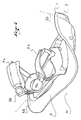
- FIG. 1 represents a three quarter front view of the lift machine assembly and spatula.
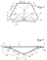
- FIG. 2 schematically represents a front view of the spatula.
- Figure 3 shows a cross-section A-A of the spatula. This cup is positioned in Figures 2 and 4.
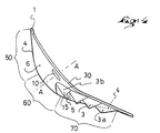
- Figure 4 schematically shows a side view of the spatula.
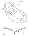
- Figure 5 is a perspective view of the spatula according to a second embodiment.
- Figure 6 is a section along VI-VI of Figure 5.
- Figure 1 illustrates a general plan of the lift which consists of a frame 0 on which is fixed the user's foot by Fx fixing means such as, for example, notched strips 55 provided with tightening loops 56.
- Fx fixing means such as, for example, notched strips 55 provided with tightening loops 56.
- Frame 0 by its surface greater than that of the foot, makes it possible to increase the lift of the user's foot on a soft support M, such as snow, sand or water, i.e. a support which does not have sufficient lift to support, without collapsing, the user.
- Frame 0 has a raised front part called tip 1, the underside of which is 2 is the subject of the description which follows, as well as a longitudinal axis 20.
- FIG 2 there is the spatula 1 in front view.
- the underside 2 of the spatula 1 includes a prominence 4 oriented substantially along the longitudinal axis 20 of the lift.
- This prominence 4 is positioned forward relative to the lateral edges 30, 31, from the underside 2 of the spatula 1.
- the protrusion 4 is connected to one of the lateral edges 30, 31, by a sliding surface 6, 6b.
- the surface of slides 6, 6b has a substantially continuous slope.
- slope surface substantially continuous a surface whose slope evolves in a substantially continuous manner. That is to say the surface does not have a very curved area, either with a small radius of curvature, or of point where a strong slope break is located.
- the prominence 4 may have a projecting edge 4a to accentuate the effect bow, and the edges 30, 31, may have very curved zones in order to achieve a homogeneous junction with frame 0.
- the underside 2 of the tip 1 includes only one and only prominence 4 positioned on the median axis of the frame 0 of the lift.
- this prominence 4 extends laterally two sliding surfaces 6, 6b, which respectively join the edges 30 and 31 of the spatula 1.
- the prominence 4 associated with the sliding surfaces 6, 6b makes it easier to exit the machine lift of snow or sand during the stride movement of the user.
- the prominence 4 provides a directional effect on the sliding which reinforces the kinematics of the movement of the user's legs during walking. This association of means avoids straining the ankles, knees and hips the user by lateral or rotating parasitic movements. It thus preserves the said joints of possible sprains.
- protrusions 4 projecting from the underside 2 of the spatula 1, which will be arranged substantially symmetrical with respect to the median axis of the lift machine.
- the two prominences located outside the spatula will be connected at the edges 30, 31, by sliding surfaces in accordance with the description above.
- the prominences will also be interconnected by sliding surfaces which have a continuous slope.
- the scales 3 are positioned substantially symmetrical with respect to the longitudinal axis 20, and are surrounded by a sliding surface 6c, 6d, respectively at the level of the lateral edges 30 and 31.
- the sliding surfaces 6c and 6d are here constituted by a downward extension sliding surfaces 6 and 6b.
- FIG. 3 illustrates the cross section A-A, positioned in FIGS. 2 and 4, in a plane perpendicular to the tip 1 of the lift.
- This figure represents a mode of embodiment in which the lower face 2 constitutes an independent part which is fixed to the spatula 1 by suitable fixing means such as screws 10.
- the face lower could also be an integral part of the spatula.
- This figure specifies the preferred geometry for sliding surfaces 6 and 6b. The following description does not relates to the sliding surface 6b, but could advantageously be applied to the surface gliding 6 in particular by symmetry with respect to the prominence 4.
- the sliding surface 6b comprises two distinct zones G1 and G2 separated by a point inflection I.
- the first zone G1 which is delimited by the prominence 4
- the surface of slide 6b defines, in transverse direction, a convex curve, that is to say that it tends to form a protruding bump on the underside of the lift.
- the sliding surface 6 defines a concave curve, it is at say that it tends to form a hollow.
- This constructive arrangement makes it possible to associate the lift of the concave part on the edges 30, 31, and the sliding of the convex part around the prominence 4.
- sliding surfaces 6, 6b which are simply convex or concave, therefore without inflection point, depending on whether one wishes to favor gliding or lift.
- Figure 4 allows to specify, thanks to its side view, the position of the scales 3 in the direction longitudinal with respect to the sliding surface 6.
- the prominence 4 comprises three zones separate.
- a raised area 50 located at the front end of the spatula 1, and extending almost vertically, a slightly raised area 70 which extends the bearing capacity of the frame 0, and a transition zone 60 which has a strong curvature and which is situated between the zone raised 50 and the slightly raised area 70.
- the gliding surface is positioned on the raised zone 50 as well as on the transition zone 60, and the scales 3, 3a, 3b, are positioned on the slightly raised area 50.
- the zones 50, 60 slide on the snow and the strong inclination of these two zones 50, 60, transforms the horizontal thrust into vertical thrust which helps to get the machine out snow.
- the scales 3, 3a, 3b which are positioned on the slightly raised area 50 are in contact with the snow and can, thanks to their concavity 5, provide retention towards the rear of the machine.
- the scales 3, 3a, 3b are arranged behind the sliding surface 6, 6b.
- the scales 3, 3a, 3b also include a sliding zone 15, located in front of the retaining concavity 5, which has a downward inclination and rearward.
- the scales 3b which are located near the transition zone 60 are set back from the prominence 4, while the scales 3a located at the opposite are arranged projecting from the prominence 4. This respect for such constructive arrangement ensures good progressiveness between the sliding function on the front of spatula 1, and the retaining function on the back of it.
- the scales 3, 3a, 3b could have different geometries in accordance with the state of the art existing in the retaining scales, just as they could be replaced by other means of restraint, in particular seal skins.
- spatula can also advantageously consist of a shell in plastic material which takes up the geometry of the underside 2 such that said shell is connected to frame 0 non-removably, or directly integrated into frame 0.
- spatula is substantially identical to that of FIGS. 1 to 4, and the same elements are therefore designated by the same references.
- the scales 3 are found in hollow on the upper face 1.
- the underside 2 of the spatula 1 and / or the frame 0 may be made of polypropylene or polyamide, as well as other thermo-injected plastics.
- the element of lift thus produced can be used, and without limitation, as a racket snow, sand racket, wake board, water surf, ... etc., that is to say with respect to any soft environment, lacking sufficient lift to support the weight of a user.
Landscapes
- Sliding-Contact Bearings (AREA)
- Rehabilitation Tools (AREA)
- Handcart (AREA)
- Floor Finish (AREA)
Abstract
Engin de portance comprenant une partie avant relevée dite spatule (1) qui assure un maintien directionnel de l'engin tout en privilégiant la glisse. La face inférieure (2) de la spatule (1) comprend une proéminence (4) orientée sensiblement selon l'axe longitudinal (20). La proéminence (4) est reliée à l'un des bords (30, 31) de la spatule (1) par une surface de glisse (6, 6b) qui présente une pente sensiblement continue. <IMAGE>Lifting machine comprising a raised front part known as a spatula (1) which provides directional maintenance of the machine while favoring sliding. The lower face (2) of the spatula (1) comprises a protrusion (4) oriented substantially along the longitudinal axis (20). The prominence (4) is connected to one of the edges (30, 31) of the spatula (1) by a sliding surface (6, 6b) which has a substantially continuous slope. <IMAGE>
Description
La présente invention concerne un engin de portance destiné à être fixé au pied de l'utilisateur et permettant d'augmenter la portance du pied sur un support mou tel que la neige, le sable ou l'eau. L'invention concerne plus spécifiquement la partie avant relevée dit spatule d'un tel engin de portance.The present invention relates to a lift device intended to be fixed to the foot of the user and making it possible to increase the lift of the foot on a soft support such as snow, sand or water. The invention relates more specifically to the raised front part called the tip. of such a lift machine.
Dans l'état de l'art antérieur, les engins de portance, de type raquette à neige, possèdent des spatules plus ou moins relevées afin de faciliter la manoeuvre de sortie de raquette de la neige durant la marche. La spatule suit un plan incurvé progressivement vers le haut. Cependant, ces spatules n'ont pas été conçues spécifiquement pour la marche mais sont inspirées des spatules d'engin de type ski ou surf. Une telle spatule sert à engager un virage et donc à pivoter, et n'assure pas le maintien directionnel de la raquette durant la marche.In the state of the prior art, lift gear, of the snowshoe type, has spatulas more or less raised to facilitate maneuvering out of snowshoes during the walk. The spatula follows a gradually curved upward plane. However, these spatulas were not designed specifically for walking but are inspired by spatulas ski or surf type equipment. Such a spatula is used to initiate a turn and therefore to pivot, and does not provide directional support of the racket during walking.
Une autre raquette à neige, décrite dans le document FR 2 760 374, comporte une spatule
amovible. Cette spatule reste dans l'art antérieur, tel que précédemment décrit, et est munie de
nervures de rigidification faisant saillies sous la spatule. Ces nervures de rigidification, même
si elles sont positionnées dans l'axe de l'engin, ne sont pas conçues pour améliorer la glisse.
En effet, elles sont raccordées à la spatule par des bords latéraux qui forment, avec la spatule,
des jonctions non progressives, renforcées éventuellement de petites nervures transversales
externes, comme illustrées sur les figures dudit document.Another snowshoe, described in
Un des buts de la présente invention est de proposer un engin de portance dont la spatule assure un maintien directionnel de l'engin tout en conservant une bonne glisse afin de faciliter le dégagement de l'engin hors du support mou durant le mouvement de marche de l'utilisateur.One of the aims of the present invention is to propose a lift machine whose spatula provides directional support of the machine while maintaining good glide to facilitate the release of the machine from the soft support during the walking movement of the user.
Un autre but de l'invention est de proposer un engin dont la spatule assure une fonction d'accroche anti-recul tout en améliorant la portance de l'engin.Another object of the invention is to propose a machine whose spatula performs a function anti-recoil grip while improving the lift of the machine.
Pour atteindre ces objectifs, l'engin de portance dispose d'une spatule qui comprend une proéminence fixée sous la face inférieure de la spatule, et orientée sensiblement selon l'axe longitudinal de l'engin. De plus, la proéminence est positionnée en avancée par rapport aux bords de la face inférieure de la spatule en formant une sorte d'étrave. Cette proéminence permet à l'engin, lorsqu'il est en appui sur la spatule, de stabiliser sa direction de mouvement selon l'axe longitudinal de l'engin. L'amélioration de la glisse de la spatule est obtenue par des surfaces de glisse qui relient la proéminence aux bords de la spatule. De plus chaque surface de glisse présente une pente continue. On pourra associer à cette spatule des écailles qui présentent une concavité apte à assurer une retenue, vers l'arrière et sur le support mou, de l'engin.To achieve these objectives, the lift has a spatula which includes a prominence fixed under the underside of the spatula, and oriented substantially along the axis longitudinal of the machine. In addition, the prominence is positioned forward relative to the edges of the underside of the spatula forming a sort of bow. This prominence allows the machine, when resting on the spatula, to stabilize its direction of movement along the longitudinal axis of the machine. The improvement of the sliding of the spatula is obtained by sliding surfaces that connect the prominence to the edges of the spatula. In addition each sliding surface has a continuous slope. We can associate scales with this spatula which have a concavity capable of ensuring retention, towards the rear and on the soft support, of the craft.
L'invention sera mieux comprise et d'autres avantages de celle-ci apparaítront à l'aide de la description en référence aux dessins en annexe qui en font partie intégrante. La description illustre, à titre d'exemples non limitatifs, certains modes de réalisations préférés.The invention will be better understood and other advantages thereof will appear with the aid of the description with reference to the attached drawings which form an integral part thereof. The description illustrates, by way of nonlimiting examples, certain preferred embodiments.
La figure 1 représente une vue de trois quart avant de l'ensemble engin de portance et spatule.FIG. 1 represents a three quarter front view of the lift machine assembly and spatula.
La figure 2 représente schématiquement une vue de face de la spatule. FIG. 2 schematically represents a front view of the spatula.
La figure 3 représente une coupe transversale A-A de la spatule. Cette coupe est positionnée sur les figures 2 et 4.Figure 3 shows a cross-section A-A of the spatula. This cup is positioned in Figures 2 and 4.
La figure 4 représente schématiquement une vue de côté de la spatule.Figure 4 schematically shows a side view of the spatula.
La figure 5 est une vue en perspective de la spatule selon un second mode de réalisation.Figure 5 is a perspective view of the spatula according to a second embodiment.
La figure 6 est une section selon VI-VI de la figure 5.Figure 6 is a section along VI-VI of Figure 5.
La figure 1 illustre un plan général de l'engin de portance qui est constitué d'un cadre 0 sur
lequel est fixé le pied de l'utilisateur par des moyens de fixation Fx tels que, par exemple, des
lanières crantées 55 munies de boucles de serrage 56. Ces moyens de fixation Fx peuvent être
articulés sur le cadre 0 ou bien être fixes.Figure 1 illustrates a general plan of the lift which consists of a
Le cadre 0, de par sa surface supérieure à celle du pied, permet d'augmenter la portance du
pied de l'utilisateur sur un support mou M, tel que de la neige, du sable ou de l'eau, c'est-à-dire
un support qui ne présente pas une portance suffisante pour soutenir, sans s'affaisser,
l'utilisateur. Le cadre 0 présente une partie avant relevée dite spatule 1 dont la face inférieure
2 fait l'objet de la description qui va suivre, ainsi qu'un axe longitudinal 20.
Sur la figure 2, on retrouve la spatule 1 en vue de face. La face inférieure 2 de la spatule 1
comprend une proéminence 4 orientée sensiblement selon l'axe longitudinal 20 de l'engin de
portance. Cette proéminence 4 est positionnée en avancée par rapport aux bords latéraux 30,
31, de la face inférieure 2 de la spatule 1. La proéminence 4 est reliée à l'un des bords latéraux
30, 31, par une surface de glisse 6, 6b. Afin d'améliorer la glisse de la spatule 1, la surface de
glisse 6, 6b, présente une pente sensiblement continue. On désigne par surface à pente
sensiblement continue une surface dont la pente évolue de façon sensiblement continue. C'est-à-dire
que la surface ne présente pas de zone très incurvée, soit à petit rayon de courbure, ou
de point où est localisée une forte rupture de pente.In Figure 2, there is the
Bien entendu, la proéminence 4 peut présenter une arête saillante 4a pour accentuer l'effet
d'étrave, et les bords 30, 31, pourront présenter des zones très incurvées afin de réaliser une
jonction homogène avec le cadre 0.Of course, the
Dans le mode de réalisation préféré, illustré aux figures 2, 3 et 4, la face inférieure 2 de la
spatule 1 ne comprend qu'une seule et unique proéminence 4 positionnée sur l'axe médian du
cadre 0 de l'engin de portance. Autour de cette proéminence 4 s'étend latéralement deux
surfaces de glisse 6, 6b, qui rejoignent respectivement les bords 30 et 31 de la spatule 1. La
proéminence 4 associée aux surfaces de glisse 6, 6b, permet de sortir plus facilement l'engin
de portance de la neige ou du sable durant le mouvement de foulée de l'utilisateur. De plus, la
proéminence 4 procure un effet directionnel sur le glissement qui vient renforcer la
cinématique du mouvement des jambes de l'utilisateur durant la marche. Cette association de
moyens permet d'éviter de solliciter les articulations des chevilles, genoux et hanches de
l'utilisateur par des mouvements parasites latéraux ou en rotation. Elle préserve ainsi les dites
articulations d'éventuelles entorses.In the preferred embodiment, illustrated in Figures 2, 3 and 4, the
Bien entendu, on pourra disposer plusieurs proéminences 4, en saillie sur la face inférieure
2 de la spatule 1, qui seront disposées sensiblement symétriques par rapport à l'axe médian de
l'engin de portance. Les deux proéminences situées à l'extérieur de la spatule seront reliées
aux bords 30, 31, par des surfaces de glisse conformes à la description ci-dessus. Les
proéminences seront également reliées entre elles par des surfaces de glisse qui présentent une
pente continue.Of course, there may be
De plus, on pourra avantageusement associer, aux moyens précédents décrits, au moins une
écaille 3, disposée sur la face inférieure 2 de la spatule 1, qui assure une fonction de retenue
de l'engin de glisse vers l'arrière. Dans le mode de réalisation préféré, décrit à la figure 1, les
écailles 3 sont positionnées sensiblement symétriques par rapport à l'axe longitudinal 20, et
sont entourées par une surface de glisse 6c, 6d, respectivement au niveau des bords latéraux
30 et 31. Les surfaces de glisse 6c et 6d sont ici constituées par un prolongement vers le bas
des surfaces de glisse 6 et 6b.In addition, it is advantageously possible to combine, with the preceding means described, at least one
La figure 3 illustre la coupe transversale A-A, positionnée sur les figures 2 et 4, dans un
plan perpendiculaire à la spatule 1 de l'engin de portance. Cette figure représente un mode de
réalisation dans lequel la face inférieure 2 constitue une pièce indépendante qui est fixée sur la
spatule 1 par des moyens de fixation appropriés tel que des vis 10. Bien entendu, la face
inférieure pourrait également faire partie intégrante de la spatule. Cette figure précise la
géométrie préférée pour les surfaces de glisse 6 et 6b. La description qui va suivre ne
concerne que la surface de glisse 6b, mais pourra être avantageusement appliquée à la surface
de glisse 6 notamment par symétrie par rapport à la proéminence 4.FIG. 3 illustrates the cross section A-A, positioned in FIGS. 2 and 4, in a
plane perpendicular to the
La surface de glisse 6b comprend deux zones distinctes G1 et G2 séparées par un point
d'inflexion I. Dans la première zone G1, qui est délimitée par la proéminence 4, la surface de
glisse 6b définit, en direction transversale, une courbe convexe, c'est à dire qu'elle a tendance
à former une bosse en saillie sur le dessous de l'engin de portance. Dans la deuxième zone
G2, qui est délimitée par le bord 30, la surface de glisse 6 définie une courbe concave, c'est à
dire qu'elle a tendance à former un creux. Cette disposition constructive permet d'associer la
portance de la partie concave sur les bords 30, 31, et la glisse de la partie convexe autour de la
proéminence 4. Bien entendu, on peut envisager des surfaces de glisse 6, 6b, qui soient
simplement convexe ou concave, donc sans point d'inflexion, selon que l'on désire privilégier
la glisse ou la portance.The sliding
La figure 4 permet de préciser, grâce à sa vue de côté, la position des écailles 3 en direction
longitudinale par rapport à la surface de glisse 6. La proéminence 4 comprend trois zones
distinctes. Une zone relevée 50 située à l'extrémité avant de la spatule 1, et s'étendant
quasiment verticalement, une zone peu relevée 70 qui prolonge la capacité portante du cadre
0, et une zone de transition 60 qui présente une forte courbure et qui est située entre la zone
relevée 50 et la zone peu relevée 70.Figure 4 allows to specify, thanks to its side view, the position of the
Afin d'obtenir le meilleur compromis entre glisse et accroche, la surface de glisse est
positionnée sur la zone relevée 50 ainsi que sur la zone de transition 60, et les écailles 3, 3a,
3b, sont positionnées sur la zone peu relevée 50. Ainsi, lorsque l'engin de portance avance
dans la neige, les zones 50, 60, viennent glisser sur la neige et la forte inclinaison de ces deux
zones 50, 60, transforme la poussée horizontale en poussée verticale qui aide à sortir l'engin
de la neige. De plus, lorsque le pied est en phase d'impulsion sur l'engin de portance, les
écailles 3, 3a, 3b, qui sont positionnées sur la zone peu relevée 50 sont en contact avec la
neige et peuvent, grâce à leur concavité 5, assurer une retenue vers l'arrière de l'engin.In order to obtain the best compromise between gliding and grip, the gliding surface is
positioned on the raised
Dans le mode de réalisation préféré, les écailles 3, 3a, 3b, sont disposées en arrière de la
surface de glisse 6, 6b. Les écailles 3, 3a, 3b, comportent également une zone de glisse 15,
située devant la concavité 5 de retenue, et qui présente une inclinaison orientée vers le bas et
vers l'arrière. De plus, les écailles 3b qui sont situées à proximité de la zone de transition 60
sont disposées en retrait par rapport à la proéminence 4, alors que les écailles 3a situées à
l'opposé sont disposées en saillie par rapport à la proéminence 4. Ce respect d'une telle
disposition constructive assure une bonne progressivité entre la fonction de glissement sur
l'avant de la spatule 1, et la fonction de retenue sur l'arrière de celle-ci.In the preferred embodiment, the
Bien entendu, les écailles 3, 3a, 3b, pourraient avoir des géométries différentes
conformément à l'état de l'art existant dans les écailles de retenue, de même qu'elles pourraient
être substituées par d'autres moyens de retenue, notamment les peaux de phoque.Of course, the
De plus, la spatule pourra également avantageusement être constituée d'une coque en
matière plastique qui reprend la géométrie de la face inférieure 2 telle que ladite coque soit
reliée au cadre 0 de façon non amovible, ou bien directement intégrée dans le cadre 0.In addition, the spatula can also advantageously consist of a shell in
plastic material which takes up the geometry of the
Un tel mode de réalisation est montré sur les figures 5 et 6 où la spatule 1 est complètement
intégrée et obtenue de moulage avec le cadre 0 de la raquette.Such an embodiment is shown in Figures 5 and 6 where the
Ceci permet d'éviter la construction à double paroi 1, 2, du mode de réalisation précédent,
et donc d'alléger sensiblement la raquette.This makes it possible to avoid the double-
Par ailleurs, la spatule est sensiblement identique à celle des figures 1 à 4, et les mêmes
éléments sont donc désignés par les mêmes références. Dans ce cas, les écailles 3 se
retrouvent en creux sur la face supérieure 1.Furthermore, the spatula is substantially identical to that of FIGS. 1 to 4, and the same
elements are therefore designated by the same references. In this case, the
La face inférieure 2 de la spatule 1 et/ou le cadre 0 pourront être réalisés en polypropylène
ou en polyamide, ainsi que d'autres matières plastiques thermo-injectées. L'élément de
portance ainsi réalisé pourra être utilisé, et de façon non limitative, en tant que raquette à
neige, raquette à sable, wake board, surf d'eau,...etc., c'est-à-dire vis à vis de tout milieu mou,
dépourvu d'une portance suffisante pour supporter le poids d'un utilisateur.The
Bien entendu, la présente invention n'est pas limitée aux modes de réalisation décrits ci-avant, qui ne sont donnés qu'à titre indicatif, mais englobe tous les modes de réalisation similaires ou équivalents.Of course, the present invention is not limited to the embodiments described above, which are given for information only, but encompasses all embodiments similar or equivalent.
Claims (12)
caractérisé en ce que la spatule (1) comprend au moins une proéminence (4) située sur la face inférieure (2) de la spatule (1) et orientée sensiblement selon l'axe longitudinal (20), et en ce que la spatule (1) comprend au moins une surface de glisse (6, 6b) qui présente une pente sensiblement continue et qui relie la proéminence (4) à l'un des bords (30, 31) de la face inférieure (2) de la spatule (1).
characterized in that the spatula (1) comprises at least one protrusion (4) located on the underside (2) of the spatula (1) and oriented substantially along the longitudinal axis (20), and in that the spatula ( 1) comprises at least one sliding surface (6, 6b) which has a substantially continuous slope and which connects the prominence (4) to one of the edges (30, 31) of the lower face (2) of the spatula ( 1).
Applications Claiming Priority (2)
| Application Number | Priority Date | Filing Date | Title |
|---|---|---|---|
| FR0001267A FR2804343B1 (en) | 2000-01-28 | 2000-01-28 | SPATULA FOR LIFT VEHICLE |
| FR0001267 | 2000-01-28 |
Publications (1)
| Publication Number | Publication Date |
|---|---|
| EP1120140A1 true EP1120140A1 (en) | 2001-08-01 |
Family
ID=8846550
Family Applications (1)
| Application Number | Title | Priority Date | Filing Date |
|---|---|---|---|
| EP01101211A Withdrawn EP1120140A1 (en) | 2000-01-28 | 2001-01-19 | Tip for a snow-shoe |
Country Status (3)
| Country | Link |
|---|---|
| US (1) | US6401367B2 (en) |
| EP (1) | EP1120140A1 (en) |
| FR (1) | FR2804343B1 (en) |
Families Citing this family (5)
| Publication number | Priority date | Publication date | Assignee | Title |
|---|---|---|---|---|
| US6981294B2 (en) * | 2002-03-04 | 2006-01-03 | Simtec, Co. | Carpet slide for recreational use |
| US20030163902A1 (en) * | 2002-03-04 | 2003-09-04 | Edwards Donald V. | Carpet slide for recreational use |
| US7780581B1 (en) * | 2004-12-20 | 2010-08-24 | Emmert Second Limited Partnership | Foot plate assembly with adjustable symmetric retention strap arrangement |
| EP3393609A4 (en) * | 2015-12-24 | 2019-09-04 | Faber Et Cie Inc. | Hybrid snowshoe-ski |
| WO2020076443A1 (en) * | 2018-10-09 | 2020-04-16 | Nike Innovate C.V. | Sole structure with progressively angled traction elements |
Citations (2)
| Publication number | Priority date | Publication date | Assignee | Title |
|---|---|---|---|---|
| FR2760374A1 (en) | 1997-03-05 | 1998-09-11 | A J R | REMOVABLE SPATULA FOR SNOWSHOES |
| FR2771301A1 (en) * | 1997-11-26 | 1999-05-28 | Salomon Sa | Snow shoe holding boot and crampons |
Family Cites Families (7)
| Publication number | Priority date | Publication date | Assignee | Title |
|---|---|---|---|---|
| US3269037A (en) * | 1965-10-13 | 1966-08-30 | Massicotte William | Foam light weight rubber snow shoes |
| US3600829A (en) * | 1970-04-27 | 1971-08-24 | Rodney M La Violette | Snowshoes |
| US3747236A (en) * | 1971-11-30 | 1973-07-24 | D Sidlauskas | Flotation shoes |
| US4004355A (en) * | 1976-05-20 | 1977-01-25 | K-Tel International, Inc. | Shoe device and method of attaching a strap to a shoe member |
| US4677765A (en) * | 1986-02-28 | 1987-07-07 | Carl Lubet | Beachrunners |
| NO158362C (en) * | 1986-03-26 | 1988-08-31 | Jan Bratland | SKOEYTE. |
| CA1266174A (en) * | 1986-12-29 | 1990-02-27 | Canstar Sports Group Inc. | Skate boot |
-
2000
- 2000-01-28 FR FR0001267A patent/FR2804343B1/en not_active Expired - Fee Related
-
2001
- 2001-01-19 EP EP01101211A patent/EP1120140A1/en not_active Withdrawn
- 2001-01-26 US US09/769,457 patent/US6401367B2/en not_active Expired - Fee Related
Patent Citations (2)
| Publication number | Priority date | Publication date | Assignee | Title |
|---|---|---|---|---|
| FR2760374A1 (en) | 1997-03-05 | 1998-09-11 | A J R | REMOVABLE SPATULA FOR SNOWSHOES |
| FR2771301A1 (en) * | 1997-11-26 | 1999-05-28 | Salomon Sa | Snow shoe holding boot and crampons |
Also Published As
| Publication number | Publication date |
|---|---|
| US6401367B2 (en) | 2002-06-11 |
| US20010010131A1 (en) | 2001-08-02 |
| FR2804343B1 (en) | 2002-03-08 |
| FR2804343A1 (en) | 2001-08-03 |
Similar Documents
| Publication | Publication Date | Title |
|---|---|---|
| EP0465794B1 (en) | Ski with a fileted upper surface | |
| FR2896424A1 (en) | SLIDING OR ROLLING BOARD | |
| EP0026148B1 (en) | Device for allowing movement on snow | |
| EP1120140A1 (en) | Tip for a snow-shoe | |
| FR2692803A1 (en) | Advanced configuration ski snow. | |
| EP0940161B1 (en) | Improved snow-shoe | |
| CH668000A5 (en) | SKI. | |
| FR2598934A1 (en) | SECURITY FIXING OF A SHOE ON A SKI | |
| FR2581322A1 (en) | Sports device of the ski type with tip | |
| EP0781158B1 (en) | Snow shoe | |
| FR2735334A1 (en) | Shoe for walking on sandy beaches | |
| CA3076032A1 (en) | Snowshoe | |
| WO2020089735A1 (en) | Snowshoe with sole comprising crampon areas | |
| FR2993785A1 (en) | SNOWBOARD BOARD ON SNOW | |
| FR2697437A1 (en) | Swimming palm. | |
| FR3075061A1 (en) | SNOW RACKET WITH SCULPTURE ELEMENTS | |
| EP1053769A1 (en) | Holding device for a boot on a snowboard | |
| FR2724358A3 (en) | Flexible toboggan construction with storage | |
| FR2775611A1 (en) | Sports vehicle for sliding downhill on snow | |
| CA3191902A1 (en) | Improved nautical assembly for sport | |
| FR2674443A1 (en) | Ski with ribbed upper face | |
| CA1163282A (en) | Apparatus for snow travel | |
| FR2744643A1 (en) | Hoe for walking on snow | |
| EP1095578A1 (en) | Skiboot | |
| FR2486407A2 (en) | Ski fixed to foot for moving on snow - has runner with raised side wall flanges turned down towards base |
Legal Events
| Date | Code | Title | Description |
|---|---|---|---|
| PUAI | Public reference made under article 153(3) epc to a published international application that has entered the european phase |
Free format text: ORIGINAL CODE: 0009012 |
|
| AK | Designated contracting states |
Kind code of ref document: A1 Designated state(s): AT BE CH CY DE DK ES FI FR GB GR IE IT LI LU MC NL PT SE TR |
|
| AX | Request for extension of the european patent |
Free format text: AL;LT;LV;MK;RO;SI |
|
| 17P | Request for examination filed |
Effective date: 20020117 |
|
| AKX | Designation fees paid |
Free format text: AT BE CH CY DE DK ES FI FR GB GR IE IT LI LU MC NL PT SE TR |
|
| STAA | Information on the status of an ep patent application or granted ep patent |
Free format text: STATUS: THE APPLICATION IS DEEMED TO BE WITHDRAWN |
|
| 18D | Application deemed to be withdrawn |
Effective date: 20040803 |