EP1119066A2 - Vorrichtung zur Behandlung eines Mediums in einem Reaktor mit einem katalysatorhaltigen Reaktionsraum - Google Patents
Vorrichtung zur Behandlung eines Mediums in einem Reaktor mit einem katalysatorhaltigen Reaktionsraum Download PDFInfo
- Publication number
- EP1119066A2 EP1119066A2 EP00125637A EP00125637A EP1119066A2 EP 1119066 A2 EP1119066 A2 EP 1119066A2 EP 00125637 A EP00125637 A EP 00125637A EP 00125637 A EP00125637 A EP 00125637A EP 1119066 A2 EP1119066 A2 EP 1119066A2
- Authority
- EP
- European Patent Office
- Prior art keywords
- reactor
- medium
- fleece
- space
- catalyst
- Prior art date
- Legal status (The legal status is an assumption and is not a legal conclusion. Google has not performed a legal analysis and makes no representation as to the accuracy of the status listed.)
- Withdrawn
Links
Images

Classifications
-
- H—ELECTRICITY
- H01—ELECTRIC ELEMENTS
- H01M—PROCESSES OR MEANS, e.g. BATTERIES, FOR THE DIRECT CONVERSION OF CHEMICAL ENERGY INTO ELECTRICAL ENERGY
- H01M8/00—Fuel cells; Manufacture thereof
- H01M8/06—Combination of fuel cells with means for production of reactants or for treatment of residues
- H01M8/0606—Combination of fuel cells with means for production of reactants or for treatment of residues with means for production of gaseous reactants
- H01M8/0612—Combination of fuel cells with means for production of reactants or for treatment of residues with means for production of gaseous reactants from carbon-containing material
- H01M8/0625—Combination of fuel cells with means for production of reactants or for treatment of residues with means for production of gaseous reactants from carbon-containing material in a modular combined reactor/fuel cell structure
- H01M8/0631—Reactor construction specially adapted for combination reactor/fuel cell
-
- B—PERFORMING OPERATIONS; TRANSPORTING
- B01—PHYSICAL OR CHEMICAL PROCESSES OR APPARATUS IN GENERAL
- B01J—CHEMICAL OR PHYSICAL PROCESSES, e.g. CATALYSIS OR COLLOID CHEMISTRY; THEIR RELEVANT APPARATUS
- B01J12/00—Chemical processes in general for reacting gaseous media with gaseous media; Apparatus specially adapted therefor
- B01J12/007—Chemical processes in general for reacting gaseous media with gaseous media; Apparatus specially adapted therefor in the presence of catalytically active bodies, e.g. porous plates
-
- B—PERFORMING OPERATIONS; TRANSPORTING
- B01—PHYSICAL OR CHEMICAL PROCESSES OR APPARATUS IN GENERAL
- B01J—CHEMICAL OR PHYSICAL PROCESSES, e.g. CATALYSIS OR COLLOID CHEMISTRY; THEIR RELEVANT APPARATUS
- B01J8/00—Chemical or physical processes in general, conducted in the presence of fluids and solid particles; Apparatus for such processes
- B01J8/02—Chemical or physical processes in general, conducted in the presence of fluids and solid particles; Apparatus for such processes with stationary particles, e.g. in fixed beds
- B01J8/0207—Chemical or physical processes in general, conducted in the presence of fluids and solid particles; Apparatus for such processes with stationary particles, e.g. in fixed beds the fluid flow within the bed being predominantly horizontal
- B01J8/0214—Chemical or physical processes in general, conducted in the presence of fluids and solid particles; Apparatus for such processes with stationary particles, e.g. in fixed beds the fluid flow within the bed being predominantly horizontal in a cylindrical annular shaped bed
-
- B—PERFORMING OPERATIONS; TRANSPORTING
- B01—PHYSICAL OR CHEMICAL PROCESSES OR APPARATUS IN GENERAL
- B01J—CHEMICAL OR PHYSICAL PROCESSES, e.g. CATALYSIS OR COLLOID CHEMISTRY; THEIR RELEVANT APPARATUS
- B01J8/00—Chemical or physical processes in general, conducted in the presence of fluids and solid particles; Apparatus for such processes
- B01J8/02—Chemical or physical processes in general, conducted in the presence of fluids and solid particles; Apparatus for such processes with stationary particles, e.g. in fixed beds
- B01J8/06—Chemical or physical processes in general, conducted in the presence of fluids and solid particles; Apparatus for such processes with stationary particles, e.g. in fixed beds in tube reactors; the solid particles being arranged in tubes
-
- C—CHEMISTRY; METALLURGY
- C01—INORGANIC CHEMISTRY
- C01B—NON-METALLIC ELEMENTS; COMPOUNDS THEREOF; METALLOIDS OR COMPOUNDS THEREOF NOT COVERED BY SUBCLASS C01C
- C01B3/00—Hydrogen; Gaseous mixtures containing hydrogen; Separation of hydrogen from mixtures containing it; Purification of hydrogen; Reversible storage of hydrogen
- C01B3/02—Production of hydrogen; Production of gaseous mixtures containing hydrogen
- C01B3/32—Production of hydrogen; Production of gaseous mixtures containing hydrogen by reaction of gaseous or liquid organic compounds with gasifying agents, e.g. water, carbon dioxide or air
- C01B3/323—Catalytic reaction of gaseous or liquid organic compounds other than hydrocarbons with gasifying agents
-
- C—CHEMISTRY; METALLURGY
- C01—INORGANIC CHEMISTRY
- C01B—NON-METALLIC ELEMENTS; COMPOUNDS THEREOF; METALLOIDS OR COMPOUNDS THEREOF NOT COVERED BY SUBCLASS C01C
- C01B3/00—Hydrogen; Gaseous mixtures containing hydrogen; Separation of hydrogen from mixtures containing it; Purification of hydrogen; Reversible storage of hydrogen
- C01B3/02—Production of hydrogen; Production of gaseous mixtures containing hydrogen
- C01B3/32—Production of hydrogen; Production of gaseous mixtures containing hydrogen by reaction of gaseous or liquid organic compounds with gasifying agents, e.g. water, carbon dioxide or air
- C01B3/34—Production of hydrogen; Production of gaseous mixtures containing hydrogen by reaction of gaseous or liquid organic compounds with gasifying agents, e.g. water, carbon dioxide or air by reaction of hydrocarbons with gasifying agents
- C01B3/38—Production of hydrogen; Production of gaseous mixtures containing hydrogen by reaction of gaseous or liquid organic compounds with gasifying agents, e.g. water, carbon dioxide or air by reaction of hydrocarbons with gasifying agents using catalysts
-
- C—CHEMISTRY; METALLURGY
- C01—INORGANIC CHEMISTRY
- C01B—NON-METALLIC ELEMENTS; COMPOUNDS THEREOF; METALLOIDS OR COMPOUNDS THEREOF NOT COVERED BY SUBCLASS C01C
- C01B3/00—Hydrogen; Gaseous mixtures containing hydrogen; Separation of hydrogen from mixtures containing it; Purification of hydrogen; Reversible storage of hydrogen
- C01B3/50—Separation of hydrogen or hydrogen-containing gases from gaseous mixtures, e.g. purification
- C01B3/56—Separation of hydrogen or hydrogen-containing gases from gaseous mixtures, e.g. purification by contacting with solids; Regeneration of used solids
- C01B3/58—Separation of hydrogen or hydrogen-containing gases from gaseous mixtures, e.g. purification by contacting with solids; Regeneration of used solids including a catalytic reaction
- C01B3/583—Separation of hydrogen or hydrogen-containing gases from gaseous mixtures, e.g. purification by contacting with solids; Regeneration of used solids including a catalytic reaction the reaction being the selective oxidation of carbon monoxide
-
- H—ELECTRICITY
- H01—ELECTRIC ELEMENTS
- H01M—PROCESSES OR MEANS, e.g. BATTERIES, FOR THE DIRECT CONVERSION OF CHEMICAL ENERGY INTO ELECTRICAL ENERGY
- H01M8/00—Fuel cells; Manufacture thereof
- H01M8/06—Combination of fuel cells with means for production of reactants or for treatment of residues
- H01M8/0662—Treatment of gaseous reactants or gaseous residues, e.g. cleaning
-
- C—CHEMISTRY; METALLURGY
- C01—INORGANIC CHEMISTRY
- C01B—NON-METALLIC ELEMENTS; COMPOUNDS THEREOF; METALLOIDS OR COMPOUNDS THEREOF NOT COVERED BY SUBCLASS C01C
- C01B2203/00—Integrated processes for the production of hydrogen or synthesis gas
- C01B2203/04—Integrated processes for the production of hydrogen or synthesis gas containing a purification step for the hydrogen or the synthesis gas
- C01B2203/0435—Catalytic purification
- C01B2203/044—Selective oxidation of carbon monoxide
-
- C—CHEMISTRY; METALLURGY
- C01—INORGANIC CHEMISTRY
- C01B—NON-METALLIC ELEMENTS; COMPOUNDS THEREOF; METALLOIDS OR COMPOUNDS THEREOF NOT COVERED BY SUBCLASS C01C
- C01B2203/00—Integrated processes for the production of hydrogen or synthesis gas
- C01B2203/04—Integrated processes for the production of hydrogen or synthesis gas containing a purification step for the hydrogen or the synthesis gas
- C01B2203/0465—Composition of the impurity
- C01B2203/047—Composition of the impurity the impurity being carbon monoxide
-
- Y—GENERAL TAGGING OF NEW TECHNOLOGICAL DEVELOPMENTS; GENERAL TAGGING OF CROSS-SECTIONAL TECHNOLOGIES SPANNING OVER SEVERAL SECTIONS OF THE IPC; TECHNICAL SUBJECTS COVERED BY FORMER USPC CROSS-REFERENCE ART COLLECTIONS [XRACs] AND DIGESTS
- Y02—TECHNOLOGIES OR APPLICATIONS FOR MITIGATION OR ADAPTATION AGAINST CLIMATE CHANGE
- Y02E—REDUCTION OF GREENHOUSE GAS [GHG] EMISSIONS, RELATED TO ENERGY GENERATION, TRANSMISSION OR DISTRIBUTION
- Y02E60/00—Enabling technologies; Technologies with a potential or indirect contribution to GHG emissions mitigation
- Y02E60/30—Hydrogen technology
- Y02E60/50—Fuel cells
-
- Y—GENERAL TAGGING OF NEW TECHNOLOGICAL DEVELOPMENTS; GENERAL TAGGING OF CROSS-SECTIONAL TECHNOLOGIES SPANNING OVER SEVERAL SECTIONS OF THE IPC; TECHNICAL SUBJECTS COVERED BY FORMER USPC CROSS-REFERENCE ART COLLECTIONS [XRACs] AND DIGESTS
- Y02—TECHNOLOGIES OR APPLICATIONS FOR MITIGATION OR ADAPTATION AGAINST CLIMATE CHANGE
- Y02P—CLIMATE CHANGE MITIGATION TECHNOLOGIES IN THE PRODUCTION OR PROCESSING OF GOODS
- Y02P20/00—Technologies relating to chemical industry
- Y02P20/50—Improvements relating to the production of bulk chemicals
- Y02P20/52—Improvements relating to the production of bulk chemicals using catalysts, e.g. selective catalysts
Definitions
- the invention relates to a device for treating a Medium in a reactor with a catalyst Reaction space according to the preamble of the independent claim.
- a tube bundle reactor is known is used for methanol reforming.
- a medium e.g. a gas mixture passed through pipes containing catalyst and implemented catalytically.
- the catalyst is usually as bulk material in such a reactor arranged.
- the invention has for its object a device to create a catalyst-containing reaction space, the compact, simple, space-saving and inexpensive to implement is.
- a reactor according to the invention has a catalyst-containing one Area between a first, inner subspace and one second, outer subspace, the first subspace of the second subspace is at least partially surrounded, the catalyst-containing area through a with catalyst material Provided fleece is formed and the fleece in the second Area surrounding a boundary wall between the first, inner subspace and the second, outer subspace forms.
- the fleece is preferably a metallic fleece, particularly preferably made of steel.
- the device according to the invention is very compact, and is easy to manufacture. It has a low one. Mass and is inexpensive.
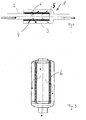
- a reactor according to the invention is through a first subspace 2 and a second subspace 3 formed by a Boundary wall 6 are separated.
- the boundary wall 6 is porous and arranged in the flow path of the medium.
- the medium flows into one part of the room, passes through the Boundary wall, is catalytically implemented there and then occurs into the other subspace and becomes reactor 1 dissipated.
- sub-rooms 2, 3 can be pipes be arranged coaxially. You can choose any Have cross-section.
- FIG. 1 A first pipe first Subspace 2 and a second pipe as a second subspace 3 one Reactor 1 are arranged coaxially to one another.
- the first pipe 2 protrudes into the second tube 3 and is on the protruding Pipe section 4 on one side with a closure 5 opposite second tube 3 closed.
- the pipe section 4 protruding into the second pipe 3 has one Wall 6 on the through a catalyst-containing, porous Body is formed.
- the wall 6 preferably consists of a wound, preferably metallic fleece, which with Catalyst material is coated. It is also possible to get one porous body is to be formed from a hollow ceramic part.
- the Wall 6 is one in the flow path into the inner tube arranged flowing medium and is from this in flows essentially radially. When crossing the porous Wall 6, the medium is converted or changed catalytically. A media flow is indicated by arrows.
- the medium enters the inner tube 2, penetrates the porous wall 6 and leaves the reactor 1 through the outer Pipe 3.
- the flow can also be reversed from the outside to the outside be inside.
- a preferred porous body to form a porous Wall 6 is a fleece.
- a fleece can be fabric-like and from fibers that are mixed or woven together or be formed from nets or from a porous foam consist. It is advantageous that such nonwovens can be shaped and their shape particularly easily desired geometries can be replicated. It is particularly favorable that fleeces are easy to coat with catalyst material.
- the nonwovens used should suitably be high Porosity with low fiber strength.
- As a coating process there are various methods known per se, such as Dipping, spraying etc.
- a preferred porous body has pores with a medium one Diameter of at most 1 mm, preferably less than 500 ⁇ m on.
- the implementation of the medium is with a coarser pore structure less satisfactory than with a finer pore structure.
- a lower advantageous pore size results e.g. from one more tolerable pressure loss across the porous body.
- FIG. 2 shows further designs of preferred reactors 1 shown. Compared to the preferred reactor in Fig. 1 these differ in an enlarged surface of the Wall 6. Comparable elements are the same Reference numerals as designated in Fig. 1.
- the length of the Fleece larger than in corrugated or folded form. So that is the catalytic surface of a wavy fleece same length of pipe section 4 is greater than in the reactor 1, in which a substantially smooth fleece is wound around a boundary wall 6 of the inner tube 2 to build.
- FIG. 2b shows a further preferred arrangement, in which the fleece, or the wall 6, in the manner of a Filter candle is formed.
- the wall 6 is essentially cylindrical.
- the folding of the fleece should clarify.
- the fleece is folded so that the circumference considerably larger when unfolded than when unfolded Status.
- FIG. 2c shows a further preferred embodiment, in which the wall 6 is conical and in Flow direction of the medium tapers.
- the wall 6 can be smooth as in Fig. 1 or in the manner of 2b designed or corrugated filter candle as in Fig. 2a.
- fleece instead of the wound fleece it is also possible to use fleece as Form honeycomb monolith, honeycomb alternating on one side are closed. This creates a high porosity of the wall 6 guaranteed.
- FIG. 3 shows a particularly preferred reactor 1, the one for the combustion of residual methanol in the exhaust gas catalytic burner in a fuel cell system is used.
- the exhaust gas should be as complete as possible be implemented.
- the exhaust gas to be converted flows into the interior of the reactor.
- the exhaust there are usually unburned hydrocarbons and hydrocarbons from combustion products in the exhaust gas.
- the hydrocarbons are burned catalytically in the reactor. This happens when the exhaust gas through the porous wall 6 in penetrates the outer peripheral region of the reactor vessel. In the Wall 6 takes place the catalytic treatment of the exhaust gas.
- the cleaned exhaust gas is then from the outer periphery of the Reactor vessel derived.
- the device according to the invention is a very compact one Arrangement. It has a low mass and is therefore special Favorable for applications where high dynamics and good Cold start properties is required, for example Fuel cell systems.
- the nonwovens are easy to coat and have one good catalyst adhesion due to sintering of the Fibers of the fleece can still be improved. At the same time they are good both before and after coating deform so that it is simply used as a boundary wall of the interior Pipe are to be installed.
- the reactor as a catalytic Burner for exhaust gas purification in a fuel cell system shows up based on the amount of catalyst used higher hydrocarbon conversion than with monoliths or Bulk reactors. Are also related to the Hydrocarbon conversion the flow losses less than in a bulk reactor.
- the efficiency of the catalyst mass used is improved combined with a long service life of the reactor.
- the device according to the invention can also be used for others Reactor types are used in the fuel cell system.
- On preferred reactor is a CO oxidation stage for selective CO removal in a hydrogen-containing gas mixture stream.
- On another preferred reactor is a reforming reactor for Reforming a medium containing hydrogen. It can do that be useful, additional catalyst material in the Flow path of the medium, for example in the inner tube and / or in the to arrange the outer tube.
Landscapes
- Chemical & Material Sciences (AREA)
- Chemical Kinetics & Catalysis (AREA)
- Organic Chemistry (AREA)
- Engineering & Computer Science (AREA)
- Inorganic Chemistry (AREA)
- Combustion & Propulsion (AREA)
- General Chemical & Material Sciences (AREA)
- Electrochemistry (AREA)
- Life Sciences & Earth Sciences (AREA)
- Sustainable Energy (AREA)
- Health & Medical Sciences (AREA)
- General Health & Medical Sciences (AREA)
- Sustainable Development (AREA)
- Manufacturing & Machinery (AREA)
- Physics & Mathematics (AREA)
- Fluid Mechanics (AREA)
- Physical Or Chemical Processes And Apparatus (AREA)
- Hydrogen, Water And Hydrids (AREA)
Abstract
Description
Claims (10)
- Vorrichtung zur Behandlung eines Mediums in einem Brennstoffzellensystem mit einem Reaktor (1) mit einem katalysatorhaltigen Bereich zwischen einem ersten Teilraum (2) des Reaktors (1) und einem zweiten Teilraum (3) des Reaktors (1), wobei der katalysatorhaltige Bereich im Strömungsweg des Mediums angeordnet und vom Medium durchströmt ist,
dadurch gekennzeichnet,daß der erste Teilraum (2) von dem zweiten Teilraum (3) zumindest bereichsweise umgeben ist,daß der katalysatorhaltige Bereich als Begrenzungswand (6) zwischen dem ersten, inneren Teilraum (2) und dem zweiten, äußeren Teilraum (3) angeordnet ist unddaß die Begrenzungswand (6) durch ein mit Katalysatormaterial versehenes Vlies gebildet ist. - Vorrichtung nach Anspruch 1,
dadurch gekennzeichnet,
daß der innere Teilraum (2) und der äußere Teilraum (3) durch zwei koaxial angeordnete Rohre gebildet sind, wobei das innere Rohr am Ende des in das äußere Rohr hineinragenden Rohrstücks (4) gegen das äußere Rohr verschlossen ist und zumindest ein Teil des Umfangs des hineinragenden Rohrstücks (4) durch das Vlies gebildet wird. - Vorrichtung nach Anspruch 1,
dadurch gekennzeichnet,
daß der innere Teilraum (2) und der äußere Teilraum (3) koaxial zueinander angeordnet sind, wobei das innere Rohr am in das äußere Rohr hineinragenden Rohrstück (4) kegelförmig ausgebildet ist und zumindest ein Teil des Umfangs des hineinragenden Rohrstücks (4) durch das Vlies gebildet wird. - Vorrichtung nach Anspruch 1,
dadurch gekennzeichnet,
daß der innere Teilraum (2) die Zuführung des Mediums in den Reaktor (1) bildet. - Vorrichtung nach Anspruch 2,
dadurch gekennzeichnet,
daß das Vlies gefaltet und/oder wellenförmig ausgebildet ist. - Vorrichtung nach Anspruch 1,
dadurch gekennzeichnet,
daß das Vlies als Wabenmonolith mit einseitig verschlossenen Waben mit zumindest zwei übereinander angeordneten Vlieslagen ausgebildet ist, so daß die Waben versetzt zueinander angeordnet sind. - Vorrichtung nach Anspruch 1,
dadurch gekennzeichnet,
daß im inneren Teilraum (2) zusätzlich Katalysatormaterial angeordnet ist. - Verwendung der Vorrichtung nach Anspruch 1 in einem katalytischen Brenner zur Abgasreinigung.
- Verwendung der Vorrichtung nach Anspruch 1 in einer CO-Oxidationsstufe zur selektiven CO-Entfernung in einem wasserstoffhaltigen Gasgemischstrom.
- Verwendung der Vorrichtung nach Anspruch 1 in einem Reformierungsreaktor zur Reformierung eines wasserstoffhaltigen Mediums.
Applications Claiming Priority (2)
| Application Number | Priority Date | Filing Date | Title |
|---|---|---|---|
| DE10002024 | 2000-01-19 | ||
| DE10002024A DE10002024C1 (de) | 2000-01-19 | 2000-01-19 | Vorrichtung zur Behandlung eines Mediums in einem Reaktor mit einem katalysatorhaltigen Reaktionsraum |
Publications (2)
| Publication Number | Publication Date |
|---|---|
| EP1119066A2 true EP1119066A2 (de) | 2001-07-25 |
| EP1119066A3 EP1119066A3 (de) | 2002-09-11 |
Family
ID=7627952
Family Applications (1)
| Application Number | Title | Priority Date | Filing Date |
|---|---|---|---|
| EP00125637A Withdrawn EP1119066A3 (de) | 2000-01-19 | 2000-11-23 | Vorrichtung zur Behandlung eines Mediums in einem Reaktor mit einem katalysatorhaltigen Reaktionsraum |
Country Status (3)
| Country | Link |
|---|---|
| US (1) | US20010024628A1 (de) |
| EP (1) | EP1119066A3 (de) |
| DE (1) | DE10002024C1 (de) |
Families Citing this family (6)
| Publication number | Priority date | Publication date | Assignee | Title |
|---|---|---|---|---|
| US20030194369A1 (en) * | 2002-04-16 | 2003-10-16 | Ravi Prasad | Gas generation system |
| US20030194368A1 (en) * | 2002-04-16 | 2003-10-16 | Devos John A. | Hydrogen production system |
| US7384609B2 (en) | 2003-01-29 | 2008-06-10 | Brp-Rotax Gmbh & Co. Kg | Pre-converter device for cleaning exhaust gas for an internal combustion engine |
| US7655196B2 (en) * | 2005-11-16 | 2010-02-02 | Fuelcell Energy, Inc. | Reforming catalyst and method and apparatus for making and loading same |
| DE102012016561B4 (de) * | 2012-08-22 | 2019-05-16 | Airbus Defence and Space GmbH | Luftfahrzeug-Brennstoffzellensystem sowie Verwendung desselben |
| US10352654B2 (en) * | 2017-08-14 | 2019-07-16 | F.N. Herstal, S.A. | Firearm with interchangeable sighting device system |
Family Cites Families (7)
| Publication number | Priority date | Publication date | Assignee | Title |
|---|---|---|---|---|
| DE1594716B1 (de) * | 1964-07-27 | 1969-11-06 | Wmf Wuerttemberg Metallwaren | Anordnung zur katalytischen Nachverbrennung von Kraftfahrzeug-Abgasen |
| US3736105A (en) * | 1971-10-06 | 1973-05-29 | J F Tourtellotte | Catalytic muffler |
| US3953176A (en) * | 1973-05-22 | 1976-04-27 | Texas Instruments Incorporated | Catalytic converter |
| FR2479323B1 (fr) * | 1980-03-31 | 1987-03-20 | Johnson Matthey Plc | Procede et dispositif anti-pollution pour gaz d'echappement de moteur a combustion interne a turbo-compresseur |
| DE4125686C2 (de) * | 1991-08-02 | 1995-05-11 | Oberland Mangold Gmbh | Abgasfilter für Brennstoffkraftmaschinen und Verfahren zur Herstellung |
| DE19526886C1 (de) * | 1995-07-22 | 1996-09-12 | Daimler Benz Ag | Verfahren und Vorrichtung zur Methanolreformierung |
| DE19721439C2 (de) * | 1997-05-21 | 1999-05-27 | Degussa | Zusatzheizung für Kraftfahrzeuge mit Verbrennungsmotoren |
-
2000
- 2000-01-19 DE DE10002024A patent/DE10002024C1/de not_active Expired - Fee Related
- 2000-11-23 EP EP00125637A patent/EP1119066A3/de not_active Withdrawn
-
2001
- 2001-01-18 US US09/761,661 patent/US20010024628A1/en not_active Abandoned
Also Published As
| Publication number | Publication date |
|---|---|
| EP1119066A3 (de) | 2002-09-11 |
| US20010024628A1 (en) | 2001-09-27 |
| DE10002024C1 (de) | 2001-06-07 |
Similar Documents
| Publication | Publication Date | Title |
|---|---|---|
| DE60027688T3 (de) | Honigwabenstruktur mit gewellter wandung und verfahren zu deren herstellung | |
| DE69200847T2 (de) | Dieselteilchen filtriervorrichtung bestehend aus perforierten rohren mit anorganischen fasern kreuzartig umwickelt, um vierseitige filterfallen zu formen. | |
| EP0892887B1 (de) | Hitzebeständiger und regenerierbarer filterkörper mit strömungswegen | |
| EP1554473B1 (de) | Abgasnachbehandlungsanordnung | |
| WO2004099577A1 (de) | Verfahren und vorrichtung zur reinigung von abgasen | |
| EP1527262B1 (de) | Abgasfilter und verfahren zum reinigen eines abgases | |
| DE10002024C1 (de) | Vorrichtung zur Behandlung eines Mediums in einem Reaktor mit einem katalysatorhaltigen Reaktionsraum | |
| EP2166203B1 (de) | Vorrichtung zur Reinigung eines Abgasstroms einer Brennkraftmaschine eines Kraftfahrzeuges, insbesondere eines Nutzfahrzeuges | |
| DE60212245T3 (de) | Verfahren und Vorrichtung zur Entfernung von Russpartikeln aus dem Abgas eines Dieselmotors | |
| WO2006072606A2 (de) | Verfahren zum entfernen von partikeln aus abgasen sowie faserlage und partikelfilter dazu | |
| WO2009065719A1 (de) | Verfahren zur herstellung eines von abgas durchströmbaren formkörpers sowie abgasanlage einer brennkraftmaschine | |
| DE19961483B4 (de) | Reinigungskatalysator für das Abgas eines Verbrennungsmotors | |
| EP2229510B1 (de) | Wabenkörper mit strukturiertem blechmaterial | |
| EP0086367A2 (de) | Vorrichtung zur Reinigung der Abgase von Dieselmotoren, insbesondere bei Kraftfahrzeugen | |
| DE60207174T2 (de) | Kegelförmige Enden für Vorrichtungen zur Abgasemissionssteuerung und Verfahren zur Herstellung | |
| DE102004054845A1 (de) | Beschichtete Partikelfalle mit Stickstoffdioxid-Neubildung | |
| DE102008003044B4 (de) | Abgasreinigungssystem zur verbesserten Abgasreinigung durch konvektives Mischen | |
| WO2009016006A1 (de) | Abgasanlage einer brennkraftmaschine | |
| DE19933442B4 (de) | Partikelfilter mit einem Filtermedium und einem Katalysator | |
| DE4125686C2 (de) | Abgasfilter für Brennstoffkraftmaschinen und Verfahren zur Herstellung | |
| EP1687086A1 (de) | Abgassystem für eine brennkraftmaschine | |
| EP1431528B1 (de) | Abgasreinigungsanordnung | |
| DE69201557T2 (de) | Dieselpartikelfilter mit konzentrischen rohren. | |
| DE19824428B4 (de) | Abgaskatalysatorkörper mit unterschiedlichen, parallelen Zellstrukturbereichen | |
| DE102008031657A1 (de) | Abgaskonverter zur katalytischen Nachbehandlung verbrennungsmotorischer Abgase sowie Abgasanlage enthaltend einen solchen |
Legal Events
| Date | Code | Title | Description |
|---|---|---|---|
| PUAI | Public reference made under article 153(3) epc to a published international application that has entered the european phase |
Free format text: ORIGINAL CODE: 0009012 |
|
| AK | Designated contracting states |
Kind code of ref document: A2 Designated state(s): AT BE CH CY DE DK ES FI FR GB GR IE IT LI LU MC NL PT SE TR |
|
| AX | Request for extension of the european patent |
Free format text: AL;LT;LV;MK;RO;SI |
|
| RAP1 | Party data changed (applicant data changed or rights of an application transferred) |
Owner name: BALLARD POWER SYSTEMS AG |
|
| PUAL | Search report despatched |
Free format text: ORIGINAL CODE: 0009013 |
|
| RIC1 | Information provided on ipc code assigned before grant |
Free format text: 7H 01M 8/06 A, 7B 01J 8/06 B, 7B 01J 8/02 B, 7C 01B 3/58 B, 7B 01J 19/24 B, 7B 01J 35/06 B, 7F 01N 3/28 B |
|
| AK | Designated contracting states |
Kind code of ref document: A3 Designated state(s): AT BE CH CY DE DK ES FI FR GB GR IE IT LI LU MC NL PT SE TR |
|
| AX | Request for extension of the european patent |
Free format text: AL;LT;LV;MK;RO;SI |
|
| AKX | Designation fees paid |
Designated state(s): DE FR GB IT |
|
| STAA | Information on the status of an ep patent application or granted ep patent |
Free format text: STATUS: THE APPLICATION IS DEEMED TO BE WITHDRAWN |
|
| 18D | Application deemed to be withdrawn |
Effective date: 20030513 |