EP1118995A1 - Magnetic storage card - Google Patents
Magnetic storage card Download PDFInfo
- Publication number
- EP1118995A1 EP1118995A1 EP00935669A EP00935669A EP1118995A1 EP 1118995 A1 EP1118995 A1 EP 1118995A1 EP 00935669 A EP00935669 A EP 00935669A EP 00935669 A EP00935669 A EP 00935669A EP 1118995 A1 EP1118995 A1 EP 1118995A1
- Authority
- EP
- European Patent Office
- Prior art keywords
- magnetic recording
- frame plate
- head
- disk
- card
- Prior art date
- Legal status (The legal status is an assumption and is not a legal conclusion. Google has not performed a legal analysis and makes no representation as to the accuracy of the status listed.)
- Withdrawn
Links
- 239000000463 material Substances 0.000 claims abstract description 23
- 239000000758 substrate Substances 0.000 claims description 41
- 238000004804 winding Methods 0.000 claims description 16
- 238000000034 method Methods 0.000 claims description 6
- 230000008569 process Effects 0.000 claims description 5
- 230000015572 biosynthetic process Effects 0.000 claims description 4
- RYGMFSIKBFXOCR-UHFFFAOYSA-N Copper Chemical compound [Cu] RYGMFSIKBFXOCR-UHFFFAOYSA-N 0.000 claims description 3
- 239000011889 copper foil Substances 0.000 claims description 3
- 239000000696 magnetic material Substances 0.000 claims 1
- 230000007246 mechanism Effects 0.000 description 15
- 230000000694 effects Effects 0.000 description 6
- 230000002452 interceptive effect Effects 0.000 description 6
- 239000000470 constituent Substances 0.000 description 5
- 230000033001 locomotion Effects 0.000 description 5
- 230000002093 peripheral effect Effects 0.000 description 4
- 230000001105 regulatory effect Effects 0.000 description 4
- 239000000853 adhesive Substances 0.000 description 3
- 230000001070 adhesive effect Effects 0.000 description 3
- 230000009471 action Effects 0.000 description 2
- 230000001276 controlling effect Effects 0.000 description 2
- 230000006870 function Effects 0.000 description 2
- WABPQHHGFIMREM-UHFFFAOYSA-N lead(0) Chemical compound [Pb] WABPQHHGFIMREM-UHFFFAOYSA-N 0.000 description 2
- 230000035699 permeability Effects 0.000 description 2
- 229920005989 resin Polymers 0.000 description 2
- 239000011347 resin Substances 0.000 description 2
- 238000009825 accumulation Methods 0.000 description 1
- 230000000052 comparative effect Effects 0.000 description 1
- 230000002950 deficient Effects 0.000 description 1
- 230000005484 gravity Effects 0.000 description 1
- 230000010365 information processing Effects 0.000 description 1
- 238000003780 insertion Methods 0.000 description 1
- 230000037431 insertion Effects 0.000 description 1
- 230000007257 malfunction Effects 0.000 description 1
- 230000009467 reduction Effects 0.000 description 1
- 230000004044 response Effects 0.000 description 1
- 230000000630 rising effect Effects 0.000 description 1
- 229910001220 stainless steel Inorganic materials 0.000 description 1
- 239000010935 stainless steel Substances 0.000 description 1
- 229920003002 synthetic resin Polymers 0.000 description 1
- 239000000057 synthetic resin Substances 0.000 description 1
Images




Classifications
-
- G—PHYSICS
- G11—INFORMATION STORAGE
- G11B—INFORMATION STORAGE BASED ON RELATIVE MOVEMENT BETWEEN RECORD CARRIER AND TRANSDUCER
- G11B25/00—Apparatus characterised by the shape of record carrier employed but not specific to the method of recording or reproducing, e.g. dictating apparatus; Combinations of such apparatus
- G11B25/04—Apparatus characterised by the shape of record carrier employed but not specific to the method of recording or reproducing, e.g. dictating apparatus; Combinations of such apparatus using flat record carriers, e.g. disc, card
-
- G—PHYSICS
- G11—INFORMATION STORAGE
- G11B—INFORMATION STORAGE BASED ON RELATIVE MOVEMENT BETWEEN RECORD CARRIER AND TRANSDUCER
- G11B33/00—Constructional parts, details or accessories not provided for in the other groups of this subclass
- G11B33/12—Disposition of constructional parts in the apparatus, e.g. of power supply, of modules
- G11B33/121—Disposition of constructional parts in the apparatus, e.g. of power supply, of modules the apparatus comprising a single recording/reproducing device
-
- G—PHYSICS
- G11—INFORMATION STORAGE
- G11B—INFORMATION STORAGE BASED ON RELATIVE MOVEMENT BETWEEN RECORD CARRIER AND TRANSDUCER
- G11B21/00—Head arrangements not specific to the method of recording or reproducing
- G11B21/16—Supporting the heads; Supporting the sockets for plug-in heads
-
- G—PHYSICS
- G11—INFORMATION STORAGE
- G11B—INFORMATION STORAGE BASED ON RELATIVE MOVEMENT BETWEEN RECORD CARRIER AND TRANSDUCER
- G11B21/00—Head arrangements not specific to the method of recording or reproducing
- G11B21/16—Supporting the heads; Supporting the sockets for plug-in heads
- G11B21/22—Supporting the heads; Supporting the sockets for plug-in heads while the head is out of operative position
-
- G—PHYSICS
- G11—INFORMATION STORAGE
- G11B—INFORMATION STORAGE BASED ON RELATIVE MOVEMENT BETWEEN RECORD CARRIER AND TRANSDUCER
- G11B25/00—Apparatus characterised by the shape of record carrier employed but not specific to the method of recording or reproducing, e.g. dictating apparatus; Combinations of such apparatus
- G11B25/04—Apparatus characterised by the shape of record carrier employed but not specific to the method of recording or reproducing, e.g. dictating apparatus; Combinations of such apparatus using flat record carriers, e.g. disc, card
- G11B25/043—Apparatus characterised by the shape of record carrier employed but not specific to the method of recording or reproducing, e.g. dictating apparatus; Combinations of such apparatus using flat record carriers, e.g. disc, card using rotating discs
-
- G—PHYSICS
- G11—INFORMATION STORAGE
- G11B—INFORMATION STORAGE BASED ON RELATIVE MOVEMENT BETWEEN RECORD CARRIER AND TRANSDUCER
- G11B5/00—Recording by magnetisation or demagnetisation of a record carrier; Reproducing by magnetic means; Record carriers therefor
- G11B5/10—Structure or manufacture of housings or shields for heads
- G11B5/11—Shielding of head against electric or magnetic fields
Landscapes
- Engineering & Computer Science (AREA)
- Manufacturing & Machinery (AREA)
- Moving Of Heads (AREA)
- Supporting Of Heads In Record-Carrier Devices (AREA)
- Magnetic Heads (AREA)
Abstract
Description
- This invention relates to a card-type magnetic recording device, which is mounted to a portable computer for input or output of information to or from the computer.
- Insertion of a card-type magnetic recording device in the shape of a PC card into a slot of a portable computer for supply of information from the magnetic recording device to the computer or vice versa permits the computer to increase a processing data capacity and also to provide additional functions.
- In such a card-type magnetic recording device, a case body is generally composed of a frame, a frame plate formed together with the frame in one united body and upper and lower covers for covering the upside and the underside of the frame plate.
- In addition to the frame plate, a circuit substrate mounted with elements on one surface is housed in the case body in the state of overlap with the frame plate. A space for housing a cartridge formed by housing a disk-shaped recording medium (which will be hereinafter referred to as a disk) in a shell is formed in the case body.
- Further, various components such as a recording/reproducing head body for reading and writing information from and to the disk, a drive device for swinging a head arm of the recording/reproducing head body, a drive device (a motor) for revolving the disk, a lock means for holding the disk in the case and an ejector mechanism for ejecting the disk toward the outside of the case are mounted on one surface (the surface on the side of the circuit substrate) of the frame plate.
- Most card-type recording devices in general use have dimensions based on PCMCIA standard Type II. According to this standard, dimensions of the case body of the card-type recording device are regulated to be 54.0 mm in width, 85.0 mm in length and 5.0 mm in thickness.
- Thus, a considerable contrivance is required for housing the frame plate mounted with various components for recording/reproduction and revolution of the disk on one surface, together with the circuit substrate or the like mounted with the elements on one surface, in the case body having such a narrow space (a small thickness in particular), while securing a cartridge housing space in the case body.
- Further, when the head is not in a disk access position, in other words, the head is placed in a standby position without reading or writing information from or to the disk, the head (and the head arm which carries the head) is placed distant from the disk in the radial direction of the disk, and moreover, the head is placed in a location further above the upside of the disk than it is placed in a location for readout of information from the upper side of the disk, and/or further below the underside of the disk than it is placed in a location for readout of information from the underside of the disk.
- Thus, it is particularly necessary to take measures to prevent the (upper) head and the head arm from interfering with the other member (an upper cover, for instance) located above the upper head and the head arm, and/or preventing the (lower) head and the head arm from interfering with the other member (the frame plate, particularly) located below the lower head and the head arm, when the head and the head arm are in the standby position within the thin case body.
- Further, the head for readout and writing of information from and to the disk is housed in a narrow space in the case body in close proximity to other components, and is therefore easily affected by electromagnetic noise originating from the elements mounted on the circuit substrate or a magnetic field generated from a stator coil as one of constituents of a disk drive motor, resulting in head reading/writing malfunctions.
- It is an object of the present invention to secure a space, which is sufficient to permit a magnetic recording/reproducing head mounted on a head arm to be moved between a recording/reproducing position to obtain access of the head to a disk-shaped recording medium loaded in the device and a standby position to place the head in a location distant from the disk-shaped recording medium without interference of the head with other members arranged in the device, in a card-type magnetic recording device having dimensions regulated to meet the standard. Another object is to provide a means of preventing the magnetic recording/reproducing head from being affected by electromagnetic noise and a magnetic field originating from other components or elements close to each other in a limited space.
- To attain the above objects, a card-type magnetic recording device according to the present invention comprises a disk housing space for housing a disk-shaped recording medium; a head arm carrying a magnetic recording/reproducing head and causing the magnetic recording/reproducing head to move between a recording/reproducing position to obtain access to the disk-shaped recording medium loaded in the disk housing space and a standby position at a distance from the disk-shaped recording medium; a frame plate which mounts the head arm and a disk drive device for driving the disk-shaped recording medium loaded in the disk housing space, on one surface thereof; and a circuit substrate, located on the other surface of the frame plate in overlap arrangement, having a plurality of elements arranged on the surface opposite to the surface facing the frame plate; wherein the frame plate has an opening or a concave part allowing the magnetic recording/reproducing head placed in the standby position and/or a part of the head arm to be housed therein. Thus, the magnetic recording/reproducing head can be moved between the standby position and the recording/reproducing position without interfering with the frame plate.
- The opening formed in the frame plate having a thickness of 0.4mm permits the magnetic recording/reproducing head placed in the standby position to be lowered further by about 0.4 mm. On the other hand, while the concave part may be formed in the frame plate by reducing the thickness of a part of the frame plate, the permissible length to lower the magnetic recording/reproducing head is limited in this case. However, the concave part formed by projecting the frame plate by means of drawing or the like increases the permissible length to lower the magnetic recording/reproducing head more than that in the above case.
- According to one mode of the card-type magnetic recording device according to the present invention, the head arm is composed of an upper arm which carries the magnetic recording/ reproducing head to gain access to the upside of a disk-shaped recording medium and a lower arm carrying the recording/reproducing head to gain access to the underside of the disk-shaped recording medium. Then, a part of the lower head arm and/or the head mounted on the arm may be housed in the opening or the concave part formed in the frame plate, and the distance between the magnetic recording/reproducing head mounted on the upper arm and the magnetic recording/reproducing head mounted on the lower arm in this state is made wider than the distance between the above magnetic recording/reproducing heads placed in the recording/reproducing position.
- An electromagnetic shield material such as copper foil is adhered to the surface opposite to the circuit substrate in the frame plate using an adhesive so as to cover the opening. In this case, the copper foil has a thickness of about 40 µm, and the adhesive has a thickness of about 30 µm.
- Instead of forming the opening, a concave part may be formed by reducing the thickness of a part of the frame plate. The portion having a reduced thickness is also used for the electromagnetic shield material.
- Any digital IC is not arranged in a magnetic recording/reproducing head operation area and its neighborhood area on the circuit substrate, but an analog IC can be arranged in the above areas. Thus, noise originating from the digital IC can be prevented from having an effect on the magnetic recording/reproducing head. The magnetic recording/reproducing head is hardly affected by the analog IC.
- Further, the disk drive device is a motor, and a stator of the motor is composed of a plurality of winding parts formed by winding a plurality of cores with coils. However, a core placed in a location corresponding to the magnetic recording/reproducing head operation area is exposed to the outside without being wound with a coil. Thus, the magnetic recording/reproducing head can be prevented from being affected by magnetic noise originating from the winding parts.
-
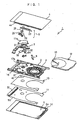
- Fig. 1 is an exploded view showing a card-type magnetic recording device in the first embodiment according to the present invention;
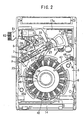
- Fig. 2 is a plan view showing the inside of the card-type magnetic recording device of Fig. 1 with an upper cover removed;
- Fig. 3 is a plan view showing a frame plate in the card-type magnetic recording device of Fig. 1 as seen from the outside, together with a frame mounted on the frame plate in one united body;
- Fig. 4A is a perspective view showing the frame plate of Fig. 3 as seen from the inside;
- Fig. 4B is a perspective view showing the frame plate of Fig. 4A as seen from the outside;
- Fig. 5 is a perspective view (partly in section) for illustrating a structure in which the frame plate of the card type magnetic recording device of Fig. 1 has an opening in a location facing a head standby position and this opening is covered with an electromagnetic shield;
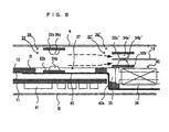
- Fig. 6 is a sectional view corresponding to the perspective view of Fig. 5;
- Fig. 7 is a plan view showing a card-type magnetic recording device in the second embodiment according to the present invention having various IC elements arranged on the element mounting surface of a circuit substrate;
- Fig. 8 is a view showing IC elements arrangement as a comparative embodiment for illustrating effects based on the arrangement of IC elements on the circuit substrate of Fig. 7; and
- Fig. 9 is a plan view showing the inside of a card-type magnetic recording device in the third embodiment according to the present invention with an upper cover removed.
-
- A description will now be given of the outline of a card-type
magnetic recording device 1 according to the present invention with reference to Figs. 1 to 4A. - An
upper cover 4 and alower cover 5 are provided as a molded product obtained by pressing a thin SUS plate and are mounted on aframe 2 in one united body by engaging the opposite sides of thecovers frame 2 from outside, providing a case body of the card-typemagnetic recording device 1. The size of the case body, that is, dimensions (width × length × thickness) of the card-typemagnetic recording device 1 are based on PCMCIA standard type II to be 54.0 mm in width, 85.60 mm in length and 5.0 mm or less in width. Further, each oflower stage parts lower covers lower stage part 4a of theupper cover 4 and thelower stage part 5a of thelower covers 5 is set to be 3.30 mm. - Further, a
frame plate 3 is provided as a molded product obtained by pressing a stainless steel plate (SUS plate) and are outsert-molded together with thesynthetic resin frame 2 in one united body, providing the structural and strength foundations of the card-typemagnetic recording device 1. - An
insulating sheet 10 and acircuit substrate 11 are housed in the case body, in addition to theframe plate 3. - Various components such as a
main ejector mechanism 6, a sub ejector mechanism 9, a magnetic recording/reproducinghead body 7 and adisk drive motor 8 are mounted on the upside of theframe plate 3. - A
cartridge 12 having amagnetic recording disk 13 housed therein is inserted into the card-typemagnetic recording device 1. Further, thecartridge 12 inserted into the card-typemagnetic recording device 1 is ejected to the outside of the device through the operation of themain ejector mechanism 6 and the sub ejector mechanism 9. - The
lower cover 5 as one of the constituents of the case body has ashutter 14. The shutter14 is urged by the action of a spring to be held in a rising state at all times. On the other hand, theshutter 14 falls down through forward pivotal motions about the lower end when pressed by the end of thecartridge 12. - A description will now be given of the
frame plate 3 with reference to Fig. 3 showing the underside of the frame plate and Fig. 4A showing the upside thereof. - A cut-out
hole 15 is formed at one side (the left side in Fig. 3) of a front part of theframe plate 3, and amounting hole 15 is formed at the other side (the right side in Fig. 3) thereof. The cut-out hole15 is used for holding a FPC 61 (see Fig. 2). An upper yoke17a, a lower yoke 17b and astator magnet 18 as constituents of the magnetic recording/reproducing head body 7 (see Fig. 1) are mounted in the mountinghole 16. - Further, a
concave part 20 for mounting a pivotal axis 21 (see Fig. 2) of the magnetic recording/reproducinghead body 7 is formed in the front part of theframe plate 3 at an approximately intermediate position between the cut-out hole 15 and the mountinghole 16. - On the other hand, a
concave part 19 having a circular cross-sectional shape for mounting thedisk drive motor 8 is formed in a rear part of theframe plate 3 by means of drawing, as shown in Fig. 4A. Ahole 39 for mounting a bearing (not shown) of thedisk drive motor 8 is formed in the center of the bottom surface of theconcave part 19. Then, a plurality of (18 pieces in Figs. 3 and 4A)coil mounting slots 38 extending from the center of thecenter hole 39 in a radial direction are formed in the bottom surface of theconcave part 19. - The
disk drive motor 8 is composed of astator 45 and a rotor 44. Thestator 45 has radially-extending magnetic cores (not shown) as many as (eighteen pieces) thecoil mounting slots 38 in locations around the axis of rotation of the rotor 44. The eighteen pieces ofcoil winding parts 45d are formed by winding each of the eighteen pieces of cores with coil wires a predetermined number of turns. Thesecoil winding parts 45d are placed in locations corresponding to the eighteen pieces ofcoil mounting slots 38 formed in the bottom surface of theconcave part 19. - Further, as shown in Fig. 4A,
open holes 36 as many as thecoil mounting slots 38 are formed in aperipheral wall 35 of theconcave part 19 in locations corresponding to the middles of theadjacent slots 38 in the bottom surface of theconcave part 19. Theseopen holes 36 are for relief of stress resulting from a process of drawing, and it is necessary to form the open holes in a material of aflat frame plate 3 before being subjected to drawing. Incidentally, eachopen hole 36 may extend from theperipheral wall 35 of the motor-mountingconcave part 19 to the bottom surface of the concave part 19 (to the middle between the adjacent slots 38). - On the other hand, the rotor 44 has a ring-shaped
permanent magnet 46, which attracts a hub of themagnetic recording disk 13 housed in thecartridge 12. - Further, various projecting parts functioning as axes and anchor parts of other components mounted on the
frame plate 3 are formed on the upside of theframe plate 3. - A description will now be given of the
main ejector mechanism 6 and the sub ejector mechanism 9 mounted on the upside of theframe plate 3 with reference to Figs. 1 and 2. - When the
cartridge 12 is inserted into the card-typemagnetic recording device 1, themain ejector mechanism 6 locks the insertedcartridge 12 in the card-typemagnetic recording device 1. On the other hand, when thecartridge 12 is again pushed forward a little, themain ejector mechanism 6 releases thecartridge 12 from its locked state to eject thecartridge 12 to the rear. - The
main ejector mechanism 6 comprises acam plate 22, aslider 23, anejector spring 24 and anengagement gear 25. Thecam plate 22 is supported on theframe plate 3 in a manner such that it can turn about an axis and is urged at all times so that it swings clockwise as shown in Fig. 2. Further, agrooved cam 26 is formed on one surface of thecam plate 22, and a gear 27 is formed at the peripheral edge of thecam plate 22. Apin 28 at the front end of theslider 23 is engaged with thegrooved cam 26. - When the
cartridge 12 is pushed in the card-typemagnetic recording device 1 through the opening at the rear, theslider 23 is pressed forward, themain ejector mechanism 6 is locked, and theshutter 14 of thecartridge 12 is then opened to thereby permit themagnetic recording disk 13 to be loaded in the card-typemagnetic recording device 1. - The gear 27 of the
cam plate 22 meshes with theengagement gear 25 supported on theframe plate 3 in a manner such that it can rotate about an axis. Theengagement gear 25 also has a projecting portion 29, in addition to a gear part. - The
slider 23 is arranged on the inside of one side (the left side in Fig. 2) of theframe 2 slidably, as shown in Fig. 2. - The sub ejector mechanism 9 has a
lever 47 mounted on theframe plate 3 so that it can swing about an axis, afirst return spring 48 for urging the lever to the rear (toward the ejecting direction of the cartridge) and a second return spring (not shown) subjected to accumulation of energy when thelever 47 is moved forward, as shown in Fig. 2. The sub ejector mechanism 9 permits thelever 47 urged by thefirst return spring 48 and the second return spring to push out thecartridge 2 to the rear in cooperation with themain ejector mechanism 6 when thecartridge 12 is released from its locked state. - A description will now be given of the magnetic recording/reproducing
head body 7 mounted on the upside of theframe plate 3 with reference to Figs. 1 and 2. - The magnetic recording/reproducing
head body 7 comprises a resinbase body part 31, ahead arm 32, adrive coil 33 and a magnetic recording/reproducing head (which will be hereinafter referred to as a head) 34 mounted on the end of thehead arm 32. - The
drive coil 33 and thehead arm 32 are respectively fixed to the opposite sides of thebase body part 31 in one united body. The magnetic recording/reproducinghead body 7 is mounted on theframe plate 3 as being freely pivoted about apivotal axis 21 arranged in the center of the base body part 31 (that is, a position of center of gravity of the whole magnetic recording/reproducing head body 7). A power lead wire (not shown) connected to thedrive coil 33 and a signal lead wire (not shown) connected to thehead 34 are connected to thebase body part 31. - The
head arm 32 swings about thepivotal axis 21 so that thehead 34 moves between a first position A (a standby position shown by a solid line in Fig. 2) where thehead 34 is isolated from the magnetic recording disk (hereinafter referred to as disk) 13 in the radial direction as well as in the direction of disk rotation axis and a second position B (a recording/reproducing position shown by a broken line in Fig. 2) where the head comes closer to the surface of thedisk 13 in consequence of movement from the first position A in the radial direction of thedisk 13 as well as in the direction of the disk rotation axis. An angle between the first position A and the second position B is about 30 degrees. Further, thehead arm 32 slides in the radial direction of themagnetic recording disk 13 to gain access to themagnetic recording disk 13 in the second position B (the recording/reproducing position). - A description will now be given of the
circuit substrate 11. - The
circuit substrate 11 has a power circuit, an information processing circuit, and electric elements such as a switching circuit, an amplifying circuit, a CPU and a memory (see Fig. 5) required for the above power circuit and the information circuit on the base formed mainly by a resin. Thecircuit substrate 11 is arranged on the underside of theframe plate 3 through the insulatingsheet 10. The insulatingsheet 10 is adapted to eliminate troubles of direct contact of various projection parts existing on the upside of thecircuit substrate 11 with theframe plate 3. - The
electronic element 41 is arranged on the (underside) surface of thecircuit substrate 11 opposite to the insulatingsheet 10. Anexternal connection connector 51 meeting PCMCIA standard is mounted on thecircuit substrate 11 along the front edge of thecircuit substrate 11. - Power is supplied to the
disk drive motor 8 fixed to the motorconcave part 19 of theframe plate 3 through a connector (not shown) provided on the underside of thecircuit substrate 11. A signal from the magnetic recording/reproducinghead body 7 of whichpivotal axis 21 is fitted to the axis mountingconcave part 20 of theframe plate 3 is given to a connector (not shown) provided on the underside of thecircuit substrate 11 through a signal line. Further, power is supplied from a connector (not shown) provided on the underside of thecircuit substrate 11 to the magnetic recording/reproducinghead body 7 through a power line. The signal line and the power line for connection between thecircuit substrate 11 and the magnetic recording/reproducinghead body 7 are put together in theFPC 61. Anotch part 50 to allow theFPC 61 to pass is formed at one side end of the circuit substrate. - A description will now be given of the first embodiment of the present invention in more detail with reference to Figs. 4B to 6.
- In the first embodiment, the
head arm 32 is composed of anupper arm 32a gaining access to the upside of themagnetic recording disk 13 and alower arm 32b gaining access to the underside of themagnetic recording disk 13. Thus, theheads 34 are mounted on theupper arm 32a at the end thereof and also on thelower arm 32b at the end thereof, respectively, as shown byreference numerals - Figs. 5 and 6 show the state where the
upper arm 32a and thelower arm 32b as constituents of thehead arm 32 together with theheads arms upper arm 32a' and thelower arm 32b') and theheads 34a' and 34b' mounted on the ends of thearms 32a', 32b' indicate that they these arms and heads are positioned in the recording/reproducing position. - As is apparent from Figs. 5 and 6, the distance between the
upper arm 32a and thelower arm 32b on standby (or between theheads upper arm 32a' and thelower arm 32b' in process of recording/reproduction (or between theheads 34a', 34b' on standby). This is because considerations are made to move thehead arm 32 on standby to the recording/reproducing position by taking the actions of lowering theupper arm 32a from a position above themagnetic recording disk 13 toward the upside of themagnetic recording disk 13, while raising thelower arm 32b from a position below themagnetic recording disk 13 toward the underside of themagnetic recording disk 13. - An opening 37 (see Fig. 4A) for housing the
lower arm 32b and thehead 34b mounted on the end of thelower arm 32b is formed in theframe plate 3 such that the upper andlower arms magnetic recording device 1 having the dimensions regulated to meet PCMCIA Type II standard. - As a result, when the
head arm 32 is in the standby position, the end of thelower arm 32b is housed in theopening 37 formed in theframe plate 3 without being placed on theframe plate 3, as shown in Fig. 6. In consequence, thehead arm 32 can hold its open state in the card-typemagnetic recording device 1 having a thickness regulated to meet the above standard. - In movement of the
head 34 placed in the standby position to the recording/reproducing position, theupper arm 32a and thelower arm 32b as constituents of thehead arm 32 moves to the positions (the recording/reproducing positions) shown byreference numerals 32a', 32b' in Figs. 5 and 6, while being guided by a guide mechanism (not shown) in a direction of coming closer to themagnetic recording disk 13 as shown by dotted lines with arrows in Figs. 5 and 6. - While the
opening 37 is formed in theframe plate 3 to eliminate the interference of thelower arm 32b of thehead arm 32 with theframe plate 3 as shown in Figs. 5 and 6, a concave part may be formed, instead of theopening 37, if a reduction in thickness of a part of the frame plate 3 (that is, formation of the concave part) makes it possible to prevent thelower arm 32b from interfering with theframe plate 3. As described above, either forming an opening in theframe plate 3 or a concave part by locally reducing the thickness of the frame plate can prevent thehead arm 32 from interfering with theframe plate 3. - When the
opening 37 is formed in theframe plate 3, the electromagnetic noise originating from theelectronic element 41 mounted on thecircuit substrate 11 arranged on the underside of theframe plate 3 through the insulatingsheet 10 reaches the head 34 (34a, 34b) placed in the standby position through theopening 37 and as a result, has an effect on the head. To avoid the above situation, it is necessary to cover theopening 37 formed in theframe plate 3 with anelectromagnetic shield material 40 adhered to the underside of theframe plate 3 with an adhesive, as shown in Fig. 4A. Since theopening 37 of theframe plate 3 is covered with theelectromagnetic shield material 40, the electromagnetic noise originating from theelectronic element 41 mounted on thecircuit substrate 11 may be restrained from reaching the head 34 (34a, 34b) through theopening 37. - Incidentally, the
electromagnetic shield material 40 may extend toward theconcave part 19 for mounting the disk drive motor, formed in theframe plate 3, to cover one or more (two in the embodiment in Fig. 4B)open holes 36 near the head 34 (34a, 34b) among the eighteen pieces ofopen holes 36 formed in the peripheral wall of theconcave part 19, as shown in Figs. 4B, 5 and 6. Also, theelectromagnetic shield material 40 may extend therefrom to cover one or more (two in the embodiment in Fig. 4B)coil mounting slots 38 near the head 34 (34a, 34b) among the eighteen pieces ofcoil mounting slots 38. - Fig. 4B shows an embodiment wherein an
electromagnetic shield material 40a for covering theopen holes 36, theelectromagnetic shield material 40 for covering theopening 37 and theelectromagnetic shield material 40 for covering thecoil mounting slots 38 are formed in one united body. Instead of this structure, the aboveelectromagnetic shield materials 40 may be formed individually. - As has been described above, the card-type
magnetic recording device 1 according to the first embodiment of the present invention makes it possible to prevent thehead arm 32 and thehead 34 placed in the standby position from interfering with theframe plate 3 within the card-type magnetic recording device having a limited thickness, by forming theopening 37 in the part of theframe plate 3 or forming the concave part instead of theopening 37. - Further, the
opening 37 formed in theframe plate 3 is covered with theelectromagnetic shield material 40 so that the influence of the electromagnetic noise, originating from thecircuit substrate 11 and passing through theopening 37, on thehead 34 can be reduced. - Further, the
coil mounting slots 38 formed in theframe plate 3 for arrangement of thestator coil 45 and theopen holes 36 formed in theframe plate 3 for relief of stress resulting from a process of drawing for formation of the motor mountingconcave part 19 may be covered with theelectromagnetic shield material 40a, so that the influence of the noise, originating from the circuit substrate and passing through theslots 38 and theopen holes 36, on thehead 34 can be reduced. - A description will now be given of the outline of a card-type
magnetic recording device 1 in the second embodiment according to the present invention with reference to Figs. 7 and 8. - As shown in Fig. 7, a
connector 70 connected to a connector terminal 62 (see Fig. 2) formed at the end of theFPC 61 is mounted on thecircuit substrate 11 in the proximity of anotch part 50. Further, essential ICs such as a readcircuit analog IC 81, amotor drive IC 82 for controlling drive of the disk drive motor and the drive motor of the magnetic recording/reproducinghead body 7, alogic IC 83 for converting a mode of a signal to and from external information equipment (not shown), alogic IC 84 for supporting the deficient functions of thelogic IC 83, a MPU and alogic IC 85 for controlling the whole motions of themagnetic recording disk 13 for recording, reproduction and driving, amemory IC 86 for storing the basic software and apower supply IC 87 are mounted on thecircuit substrate 11. - Among the above essential ICs, the read
circuit analog IC 81 and themotor drive IC 82 are analog ICs, while thelogic ICs logic IC 85, thememory IC 86 and thepower supply IC 87 are digital ICs,. - An imaginary line in Fig. 7 shows that the
head 34, which is arranged above thecircuit substrate 11, moves within an operation area between the first position A (corresponding to the position A in Fig. 2) and the second position B (corresponding to the position B in Fig. 2). - As shown in Fig. 7, it is a features of the second embodiment that considerations are made not to arrange any digital ICs in the operation area of the
head 34 on thecircuit substrate 11. This is because current supplied to the analog IC (ICs 81, 82) is several mV, whereas current supplied to the digital IC (ICs 83 to 87) is in the range of 0 to 5V, with the result that noise originates from the digital IC exclusively and has an effect on thehead 34. - Thus, if the arrangement of the essential ICs (
ICs 81 to 87) is made as shown in Fig. 8, the noise originating from thelogic IC 84 provided as the digital IC arranged in the operation area of thehead 34 has an effect on the head, resulting in occurrence of errors in recording and reproduction to and from themagnetic recording disk 13. - In Fig. 7, the read
circuit analog IC 81 is arranged in the operation area of thehead 34 on thecircuit substrate 11. This is because theIC 81 is an IC which operates in response to a feeble signal, and therefore, is affected by the noise if theIC 81 is arranged distant from theconnector 70 to make a wiring pattern longer. For that reason, theIC 81 needs to be arranged close to the connector to prevent theIC 81 from being affected by the noise as much as possible. - As has been described above, the card-type
magnetic recording device 1 in the second embodiment according to the present invention makes it possible to prevent the noise originating from the digital ICs from having an effect on thehead 34 by arranging the digital ICs on thecircuit substrate 11 outside the operation area of the head of the magnetic recording/reproducing head body. The analog ICs may be arranged in the operation area of thehead 34 of the magnetic recording/reproducing head body on thecircuit substrate 11. - A description will now be given of the outline of a card-type
magnetic recording device 1 in a third embodiment according to the present invention with reference to Fig. 9. - In the above card-type
magnetic recording device 1 shown in Fig. 2, thehead 34 may be affected by the magnetic noise originating from one windingpart 45d located close to thehead 34 placed in the position B (the recording/reproducing position) in Fig. 2 among eighteen pieces of windingparts 45d forming the stator of the disk drive motor, resulting in hindrance of normal writing and readout operations. - For avoiding the above problem, it is well-known to project a flange from a member which supports a stator of a motor for driving a magnetic recording disk so as to separate the stator from the magnetic disk (and the magnetic head) and then adhere a magnetic shield thin plate consisting of a material of high magnetic permeability to the stator-side surface of the flange, forming a closed magnetic circuit with the stator, a rotor magnet facing the stator, a rotor holder for holding the rotor magnet, the stator and the flange. (Refer to Japanese Utility Model Publication No. 2-2066) However, the well-known technique has a disadvantage in that the magnetic shield thin plate consisting of the material of high magnetic permeability is expensive, and much labor is required for adhering the magnetic thin plate to a predetermined position of the flange.
- According to the third embodiment, the problems with the above prior art are dissolved by providing a non-winding part C formed by winding no coil around one
core 45e located close to thehead 34 placed in the recording/reproducing position (the position B of Fig. 9) to expose thecore 45e to the outside. - In Fig. 9, the
head arm 32 makes swing motions about thepivotal axis 21 between the standby position (the position A shown by a solid line in Fig. 9) where thehead 34 mounted on the end of the head arm takes retreat from the disk area and the recording/reproducing position (the position B shown by a broken line in Fig. 9) where thehead 34 comes closer to the surface of themagnetic recording disk 13 for recording and reproduction, similarly to the head arm shown in Fig. 2. - Even if one of eighteen pieces of winding
parts 45d forming thestator 45 of thedisk drive motor 8 is made non-winding part C, driving of thedisk drive motor 8 is hardly influenced. - According to the third embodiment, since the head may be protected from the influence of the magnetic noise originating from the winding
parts 45d only by winding no coil around one of a plurality of cores, it is possible to provide a magnetic recording device which is available at a low cost and has a higher reliability in comparison with the prior art described above.
Claims (11)
- A card-type magnetic recording device comprising;a disk housing space for housing a disk-shaped recording medium;a head arm carrying a magnetic recording/reproducing head and causing the magnetic recording/reproducing head to move between a recording/reproducing position to obtain access to the disk-shaped recording medium loaded in said disk housing space and a standby position at a distance from the disk-shaped recording medium;a frame plate which mounts said head arm and a disk drive device for driving the disk-shaped recording medium loaded in said disk housing space, on one surface thereof; anda circuit substrate, located on the other surface of said frame plate in overlap arrangement, having a plurality of elements arranged on the surface opposite to the surface facing said frame plate;wherein said frame plate has an opening or a concave part allowing the magnetic recording/reproducing head placed in said standby position and/or a part of the head arm to be housed therein, allowing the magnetic recording/reproducing head to move between the standby position and the recording/reproducing position without interference with said frame plate.
- A card-type magnetic recording device according to claim 1, wherein said head arm is composed of an upper arm carrying the recording/reproducing head to gain access to the upside of the disk-shaped recording medium, and a lower arm carrying the recording/reproducing head to gain access to the underside of said disk-shaped recording medium, the part of the lower head arm and/or the head mounted on the arm is housed in the opening or concave part formed in the frame plate, and the distance between the magnetic recording/reproducing head mounted on the upper arm and the magnetic recording/reproducing head mounted on the lower arm in this state is made wider than the distance between said magnetic recording/reproducing heads placed in the recording/reproducing position.
- A card-type magnetic recording device according to claim 1, wherein said opening is closed with an electromagnetic shield material by adhering it to the surface of the frame plate on the side opposite to the circuit substrate.
- A card-type magnetic recording device according to claim 1, wherein an electromagnetic shield material is provided to close an open hole for relief of stress resulting from a process of drawing for formation of coil mounting slots in the frame plate for arrangement of a stator coil and/or a motor mounting concave part in the frame plate, on the side of the circuit substrate.
- A card-type magnetic recording device according to claim 1, wherein an electromagnetic shield material is adhered to the surface of the frame plate opposite to the circuit substrate to cover said opening, and another electromagnetic shield material is provided, integral with the electromagnetic shield material, to close an open hole for relief of stress resulting from a process of drawing for formation of coil mounting slots in the frame plate for arrangement of the stator coil and/or a motor mounting concave part in the frame plate, on the side of the circuit substrate.
- A card-type magnetic recording device according to claim 3 or 4, wherein said electromagnetic shield material is made of copper foil.
- A card-type magnetic recording device according to claim 1, wherein a reduced thickness portion obtained by forming said concave part in the frame plate also serves as an electromagnetic shield material.
- A card-type magnetic recording device according to claim 1, wherein digital ICs are arranged on the circuit substrate in an area other than an operation area from the recording/reproducing position to the retreat position and its neighborhood area, without arranging any digital ICs on the circuit substrate in the operation area of said magnetic recording/reproducing head and its neighborhood area.
- A card-type magnetic recording device according to claim 8, wherein analog ICs are arranged on the circuit substrate in the operation area of said magnetic recording/reproducing head and its neighborhood area.
- A card-type magnetic recording device according to claim 8, wherein said disk drive device is a motor provided with a stator having a plurality of winding parts formed by winding a plurality of cores with coils and a rotor driven by a revolving magnetic field generated in said stator, and the core or cores located in the operation area of said magnetic recording/reproducing head from the recording/reproducing position to the retreat position and its neighborhood area, among the plurality of cores, are not wound with coils.
- A card-type magnetic recording device according to claim 10, wherein said core is made of a magnetic material and is formed to arrange radially about the axis of rotation of said rotor, and the core or cores wound with no coil, among said cores, are exposed to the outside.
Applications Claiming Priority (7)
| Application Number | Priority Date | Filing Date | Title |
|---|---|---|---|
| JP16649299 | 1999-06-14 | ||
| JP16649299 | 1999-06-14 | ||
| JP16649399 | 1999-06-14 | ||
| JP16649399 | 1999-06-14 | ||
| JP16845299 | 1999-06-15 | ||
| JP16845299 | 1999-06-15 | ||
| PCT/JP2000/003837 WO2000077789A1 (en) | 1999-06-14 | 2000-06-13 | Magnetic storage card |
Publications (2)
| Publication Number | Publication Date |
|---|---|
| EP1118995A1 true EP1118995A1 (en) | 2001-07-25 |
| EP1118995A8 EP1118995A8 (en) | 2001-10-04 |
Family
ID=27322696
Family Applications (1)
| Application Number | Title | Priority Date | Filing Date |
|---|---|---|---|
| EP00935669A Withdrawn EP1118995A1 (en) | 1999-06-14 | 2000-06-13 | Magnetic storage card |
Country Status (5)
| Country | Link |
|---|---|
| US (1) | US6552869B1 (en) |
| EP (1) | EP1118995A1 (en) |
| KR (1) | KR20010072464A (en) |
| CN (1) | CN1168091C (en) |
| WO (1) | WO2000077789A1 (en) |
Families Citing this family (8)
| Publication number | Priority date | Publication date | Assignee | Title |
|---|---|---|---|---|
| US6762906B1 (en) * | 1998-10-30 | 2004-07-13 | Iomega Corporation | Disk drive for removable disk cartridges and receivable into a PCMCIA port of a computer |
| US8397998B1 (en) * | 1999-10-23 | 2013-03-19 | Ultracard, Inc. | Data storage device, apparatus and method for using same |
| US20050194453A1 (en) * | 2001-07-27 | 2005-09-08 | Storcard, Inc. | Enhanced smart card with rotating storage |
| KR20050088081A (en) * | 2002-11-18 | 2005-09-01 | 스토카드, 인코포레이션 | Secure transaction card with a large storage volume |
| US7012781B2 (en) * | 2003-06-18 | 2006-03-14 | Seagate Technology Llc | Laminated disc drive base |
| US7271513B2 (en) * | 2005-04-15 | 2007-09-18 | Seagate Technology Llc | Thermal stress relieved overmolded mounting base |
| US20090159703A1 (en) | 2007-12-24 | 2009-06-25 | Dynamics Inc. | Credit, security, debit cards and the like with buttons |
| CN103106905A (en) * | 2011-11-15 | 2013-05-15 | 建兴电子科技股份有限公司 | CD drive |
Family Cites Families (12)
| Publication number | Priority date | Publication date | Assignee | Title |
|---|---|---|---|---|
| US5956213A (en) * | 1988-01-25 | 1999-09-21 | Seagate Technology, Inc. | Latch mechanism for disk drive using magnetic field of actuator magnets |
| JPH022066A (en) | 1988-06-15 | 1990-01-08 | Ricoh Co Ltd | Optical data recording medium and recording method |
| JP3049452B2 (en) * | 1991-09-02 | 2000-06-05 | 日本電産株式会社 | Hard disk drive |
| JPH0562477A (en) | 1991-08-30 | 1993-03-12 | Fujitsu Ltd | Charge pump circuit |
| WO1994009486A1 (en) * | 1992-10-08 | 1994-04-28 | Integral Peripherals, Inc. | Mounting arrangement for disk drive |
| JP2842521B2 (en) | 1994-12-28 | 1999-01-06 | 三菱電機株式会社 | Interchangeable storage device, recording medium cartridge, and method of using slot for card type device |
| JPH09265771A (en) * | 1996-03-26 | 1997-10-07 | Fujitsu Ltd | Storage device |
| JPH09312068A (en) * | 1996-05-21 | 1997-12-02 | Mitsumi Electric Co Ltd | Magnetic recording / reproducing device |
| US5875074A (en) * | 1997-04-18 | 1999-02-23 | Quinta Corporation | Adjustable head loading apparatus |
| US5995332A (en) * | 1997-08-29 | 1999-11-30 | Iomega Corporation | Scissoring load ramp for a removable media disk drive |
| US6320723B1 (en) * | 1999-06-24 | 2001-11-20 | Seagate Technology Llc | Protective cover for a disc drive printed circuit board wherein the cover and a circuit board component are thermally connected |
| US6411463B1 (en) * | 1999-07-23 | 2002-06-25 | Seagate Technology Llc | Insert for dampening acoustic vibration and shielding magnetic flux for use in a disc drive |
-
2000
- 2000-06-13 CN CNB008011052A patent/CN1168091C/en not_active Expired - Fee Related
- 2000-06-13 EP EP00935669A patent/EP1118995A1/en not_active Withdrawn
- 2000-06-13 US US09/762,828 patent/US6552869B1/en not_active Expired - Fee Related
- 2000-06-13 KR KR1020017001879A patent/KR20010072464A/en not_active Ceased
- 2000-06-13 WO PCT/JP2000/003837 patent/WO2000077789A1/en not_active Ceased
Non-Patent Citations (1)
| Title |
|---|
| See references of WO0077789A1 * |
Also Published As
| Publication number | Publication date |
|---|---|
| EP1118995A8 (en) | 2001-10-04 |
| CN1313990A (en) | 2001-09-19 |
| US6552869B1 (en) | 2003-04-22 |
| WO2000077789A1 (en) | 2000-12-21 |
| CN1168091C (en) | 2004-09-22 |
| KR20010072464A (en) | 2001-07-31 |
Similar Documents
| Publication | Publication Date | Title |
|---|---|---|
| US6195225B1 (en) | Disk drive having anti-wobbling mechanism | |
| US5282099A (en) | Disk drive apparatus incorporating circuitry into housing | |
| JP3095017B2 (en) | RECORDING MEDIUM DRIVE AND ELECTRONIC DEVICE HAVING THE SAME | |
| US20050094312A1 (en) | Disk drive and electronic device provided with the same | |
| US6510026B2 (en) | Exchangeable storage apparatus, recording medium drive actuator, head drive actuator, and recording medium cartridge | |
| US6552869B1 (en) | Magnetic storage card | |
| EP0799482B1 (en) | Electronic circuit with local storage | |
| EP1120788A1 (en) | Card type magnetic recording device | |
| EP1109167B1 (en) | Disk cartridge and disk drive unit | |
| EP0984447B1 (en) | Magnetic recording device | |
| US6762906B1 (en) | Disk drive for removable disk cartridges and receivable into a PCMCIA port of a computer | |
| US7027262B2 (en) | Spindle motor structure mounted directly on a base plate of a thin type flexible disk drive | |
| US6738221B1 (en) | Magnetic recording unit with lid | |
| JPWO2000077789A1 (en) | Card-type magnetic recording device | |
| US6906891B2 (en) | Flexible disk drive having a frame structure comprising a main frame and a sub-frame of a lower cover | |
| JP3153932B2 (en) | Disk drive device and information equipment using this device | |
| JP3812107B2 (en) | Disk unit | |
| US20030002205A1 (en) | Flexible disk drive with a heat release structure for releasing self heat generated from an electronic component mounted thereto | |
| JPH02161664A (en) | Disk device | |
| JP2006048764A (en) | Disk unit | |
| JPH02162566A (en) | Disk device | |
| JPH02162565A (en) | Disk device | |
| JPH02246082A (en) | Disk device | |
| JPH02161653A (en) | Disk device | |
| JPWO1999049466A1 (en) | magnetic recording device |
Legal Events
| Date | Code | Title | Description |
|---|---|---|---|
| PUAI | Public reference made under article 153(3) epc to a published international application that has entered the european phase |
Free format text: ORIGINAL CODE: 0009012 |
|
| 17P | Request for examination filed |
Effective date: 20010214 |
|
| AK | Designated contracting states |
Kind code of ref document: A1 Designated state(s): DE FR GB IT |
|
| AX | Request for extension of the european patent |
Free format text: AL;LT;LV;MK;RO;SI |
|
| RIN1 | Information on inventor provided before grant (corrected) |
Inventor name: MUKAIJIMA, KATSUTOSHI, CITIZEN WATCH CO., LTD. Inventor name: WAKITA, MAKI, CITIZEN WATCH CO., LTD. Inventor name: TAKAHASHI, SHOJI, CITIZEN WATCH CO., LTD. Inventor name: IWAKO, AKINOBU, CITIZEN WATCH CO., LTD. Inventor name: FUJINUMA, KATSUHIKO, CITIZEN WATCH CO., LTD. Inventor name: INUYAMA, TOMOSHIGE, CITIZEN WATCH CO., LTD. |
|
| RAP1 | Party data changed (applicant data changed or rights of an application transferred) |
Owner name: CITIZEN WATCH CO. LTD. Owner name: IOMEGA CORPORATION |
|
| A4 | Supplementary search report drawn up and despatched |
Effective date: 20040204 |
|
| RIC1 | Information provided on ipc code assigned before grant |
Ipc: 7G 11B 25/04 A Ipc: 7G 11B 5/54 B Ipc: 7G 11B 21/12 B |
|
| GRAP | Despatch of communication of intention to grant a patent |
Free format text: ORIGINAL CODE: EPIDOSNIGR1 |
|
| STAA | Information on the status of an ep patent application or granted ep patent |
Free format text: STATUS: THE APPLICATION IS DEEMED TO BE WITHDRAWN |
|
| 18D | Application deemed to be withdrawn |
Effective date: 20060614 |