EP1118872A2 - Shielding device for a millimeter wave radar casing to reduce influence of ground clutter - Google Patents
Shielding device for a millimeter wave radar casing to reduce influence of ground clutter Download PDFInfo
- Publication number
- EP1118872A2 EP1118872A2 EP01101138A EP01101138A EP1118872A2 EP 1118872 A2 EP1118872 A2 EP 1118872A2 EP 01101138 A EP01101138 A EP 01101138A EP 01101138 A EP01101138 A EP 01101138A EP 1118872 A2 EP1118872 A2 EP 1118872A2
- Authority
- EP
- European Patent Office
- Prior art keywords
- transmission
- shielding member
- reception antenna
- millimeter wave
- wave radar
- Prior art date
- Legal status (The legal status is an assumption and is not a legal conclusion. Google has not performed a legal analysis and makes no representation as to the accuracy of the status listed.)
- Granted
Links
- 230000005540 biological transmission Effects 0.000 claims abstract description 35
- 239000006096 absorbing agent Substances 0.000 claims description 6
- 239000000463 material Substances 0.000 claims description 3
- 238000010792 warming Methods 0.000 claims 1
- 238000001514 detection method Methods 0.000 abstract description 7
- 238000010586 diagram Methods 0.000 description 10
- 239000002184 metal Substances 0.000 description 7
- 239000000428 dust Substances 0.000 description 5
- 230000005855 radiation Effects 0.000 description 5
- 238000007747 plating Methods 0.000 description 3
- 230000000694 effects Effects 0.000 description 2
- 238000002844 melting Methods 0.000 description 2
- 230000008018 melting Effects 0.000 description 2
- 230000003595 spectral effect Effects 0.000 description 2
- 238000001228 spectrum Methods 0.000 description 2
- 239000000853 adhesive Substances 0.000 description 1
- 230000001070 adhesive effect Effects 0.000 description 1
- 230000006866 deterioration Effects 0.000 description 1
- 230000002542 deteriorative effect Effects 0.000 description 1
- 238000009434 installation Methods 0.000 description 1
- 238000004519 manufacturing process Methods 0.000 description 1
- 238000000034 method Methods 0.000 description 1
Images




Classifications
-
- H—ELECTRICITY
- H01—ELECTRIC ELEMENTS
- H01Q—ANTENNAS, i.e. RADIO AERIALS
- H01Q1/00—Details of, or arrangements associated with, antennas
- H01Q1/52—Means for reducing coupling between antennas; Means for reducing coupling between an antenna and another structure
- H01Q1/526—Electromagnetic shields
-
- H—ELECTRICITY
- H01—ELECTRIC ELEMENTS
- H01Q—ANTENNAS, i.e. RADIO AERIALS
- H01Q1/00—Details of, or arrangements associated with, antennas
- H01Q1/40—Radiating elements coated with or embedded in protective material
- H01Q1/405—Radome integrated radiating elements
-
- H—ELECTRICITY
- H04—ELECTRIC COMMUNICATION TECHNIQUE
- H04L—TRANSMISSION OF DIGITAL INFORMATION, e.g. TELEGRAPHIC COMMUNICATION
- H04L27/00—Modulated-carrier systems
- H04L27/26—Systems using multi-frequency codes
- H04L27/2601—Multicarrier modulation systems
- H04L27/2626—Arrangements specific to the transmitter only
- H04L27/26265—Arrangements for sidelobes suppression specially adapted to multicarrier systems, e.g. spectral precoding
-
- G—PHYSICS
- G01—MEASURING; TESTING
- G01S—RADIO DIRECTION-FINDING; RADIO NAVIGATION; DETERMINING DISTANCE OR VELOCITY BY USE OF RADIO WAVES; LOCATING OR PRESENCE-DETECTING BY USE OF THE REFLECTION OR RERADIATION OF RADIO WAVES; ANALOGOUS ARRANGEMENTS USING OTHER WAVES
- G01S13/00—Systems using the reflection or reradiation of radio waves, e.g. radar systems; Analogous systems using reflection or reradiation of waves whose nature or wavelength is irrelevant or unspecified
- G01S13/88—Radar or analogous systems specially adapted for specific applications
- G01S13/93—Radar or analogous systems specially adapted for specific applications for anti-collision purposes
- G01S13/931—Radar or analogous systems specially adapted for specific applications for anti-collision purposes of land vehicles
- G01S2013/9327—Sensor installation details
- G01S2013/93271—Sensor installation details in the front of the vehicles
-
- G—PHYSICS
- G01—MEASURING; TESTING
- G01S—RADIO DIRECTION-FINDING; RADIO NAVIGATION; DETERMINING DISTANCE OR VELOCITY BY USE OF RADIO WAVES; LOCATING OR PRESENCE-DETECTING BY USE OF THE REFLECTION OR RERADIATION OF RADIO WAVES; ANALOGOUS ARRANGEMENTS USING OTHER WAVES
- G01S7/00—Details of systems according to groups G01S13/00, G01S15/00, G01S17/00
- G01S7/02—Details of systems according to groups G01S13/00, G01S15/00, G01S17/00 of systems according to group G01S13/00
- G01S7/28—Details of pulse systems
- G01S7/2813—Means providing a modification of the radiation pattern for cancelling noise, clutter or interfering signals, e.g. side lobe suppression, side lobe blanking, null-steering arrays
Definitions
- the present invention relates to a millimeter wave radar apparatus for transmitting and receiving millimeter electric waves to detect objects on the ground, and more particularly to a millimeter wave radar which is made less vulnerable to the influence of ground clutters due to side lobes.
- Conceivable radars for use in autonomous driving of vehicles and for the collision avoidance include a millimeter wave radar.
- a millimeter wave radar In a millimeter wave radar, however, background noise is increased by ground clutters generated by side lobes, especially downward ones, of the transmitted electric wave (millimeter wave), and required signals from the target are buried in the noise, resulting in a deterioration in the capability to detect the target object.
- An object of the present invention is to provide an inexpensive millimeter wave radar capable of easily reducing ground clutter noise and excelling in detection performance while minimizing the impacts on the shape and size of any conventional antenna unit.
- a millimeter wave radar antenna unit represents a solution to the problem by providing a shielding member (electric shielding material) in a lower fore part of the antenna unit comprising a transmission/reception antenna (transmit and receive antennas); a casing for accommodating the transmission/reception antenna; and a radome for protecting the transmission/reception antenna.
- a shielding member electrical shielding material
- Fig. 1 is a partial perspective sectional view of the overall structure of a radar antenna according to the invention.
- Fig. 2 illustrates the configuration of a millimeter wave radar.
- Fig. 3 is a perspective view of an embodiment of the invention in which a shielding member is directly fitted to a casing.
- Fig. 4 is a perspective view of an embodiment in which a shielding member is formed integrated with a casing.
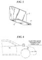
- Fig. 5 is a perspective view of an embodiment in which a shielding member is formed integrated with a radome.
- Fig. 6 is a profile of an embodiment in which a hood is used as a shielding member.
- Fig. 7 is a profile of an embodiment in which a radar antenna fitted with a shielding member is installed within a bumper.
- Fig. 8 is a profile of another embodiment in which a shielding member is fitted with a heater.
- Fig. 9 is a profile of an embodiment in which a shielding member is provided with a slit.
- Fig. 10 is a profile of an embodiment in which a reflected electric wave is utilized.
- Fig. 11 is a perspective view of a transmission/reception antenna according to the prior art.
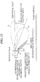
- Fig. 12 is a diagram illustrating how ground clutters arise.
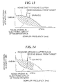
- Fig. 13 is a spectral diagram of a receive signal.
- Fig. 14 is a spectral diagram of a receive signal where a shielding member is provided.
- Fig. 2 illustrates a state in which a millimeter wave radar according to the invention is mounted on a vehicle.
- the millimeter wave radar consists of three elements including an antenna unit 11 for transmitting and receiving electric waves (millimeter wave), an indicator (a display unit) 13 for informing the driver of a target that has been detected, and a control circuit 12 for controlling the antenna 11 and the indicator 13, and the antenna unit 11 is installed on the front part of the vehicle so that it can transmit an electric wave (millimeter wave) in the running direction of the vehicle. Further, a shielding member (electric shielding material) 4 is fitted in a lower front part of the antenna unit 11.
- a shielding member (electric shielding material) 4 is fitted in a lower front part of the antenna unit 11.
- Fig. 1 is a partial perspective sectional view of the overall structure of the antenna unit 11 best illustrating a characteristic of the invention.
- a transmission/reception antenna transmit and receive antennas
- a radome 3 cover
- the antenna unit 11 is fitted to the vehicle with metal brackets 16, at the bottom of which the shielding member 4 is provided protruding from the front of the antenna unit 11.
- an antenna unit is installed in front of the vehicle for use in detection of any target existing ahead in the running direction of the vehicle.
- a Doppler radar system for instance, which is a version of millimeter wave radar, can figure out the running speed and the distance to the target by transmitting the main beam of an electric wave toward the target and observing the Doppler frequency of the electric wave reflected by the target and the phase difference between the transmitted and received electric waves.
- the transmitted wave has side lobes, and the strong reflections of the side lobes from the road surface (ground clutters) are also received by the reception antenna together with a signal from the target.
- Fig. 12 typically illustrates a side lobe 6, which generates ground clutters, and a main beam 5 in the aforementioned embodiment.
- the electric wave is supposed to be transmitted from one point on the antenna unit 11.
- the radiation angle (transmit angle) of the electric wave with reference to the horizontal plane is supposed to be ⁇ positively toward the road surface(downward direction).
- the spectrum of a receive signal in a state in which the shielding member 4 to intercept the side lobe 6 is shown in Fig. 13.
- a Doppler frequency relative to the ground surface is generated.
- the noise floor of region A attributable to a Doppler frequency at no more than 6.7 kHz mostly consists of noise attributable to ground clutters, and this noise brings down the S/N ratio, resulting in a drop in the radar's detection capability.
- X H/tan ⁇
- the relationship between the radiation angle ⁇ and the Doppler frequency fd [Hz] is represented by Equation (2).
- the spectrum of ground clutters and the receive signal in this state is shown in Fig. 14, which indicates that the level of noise due to ground clutters is reduced to that of noise generated by the electronic circuit section of the antenna unit 11, i.e. ground clutters can be almost wholly removed by the shielding member 4.
- fd 2 ⁇ V ⁇ cos ⁇ / ⁇
- V represents the moving speed (60 km/h in this case) of the antenna unit 11, and ⁇ , the wavelength of the millimeter wave (5 mm in this case).
- the shielding member 4 which can intercept or attenuate side lobes 6 is fitted to the metal brackets 16 to project from the lower front part of the transmission/reception antenna 1 as shown in Fig. 1, can reduce inexpensively and easily the impact of ground clutters due to side lobes (i.e. reduce noise) though it uses a conventional antenna unit 11 (while minimizing the increase in size of the antenna unit 11) and thereby to enhance the target detecting capability.
- the shielding member 4 may as well be fitted directly to the antenna unit 11 by adhesive 14 as illustrated in Fig. 3. Or by sticking an electric wave (millimeter wave) absorber to the electric wave (millimeter wave) reflecting surface of the shielding member 4, the intensity of the reflection of side lobes 6 by the shielding member 4 can also be reduced.
- an electric wave millimeter wave
- Fig. 4 is a schematic diagram of an example in which a shielding member is formed of the same member as and integrated with a casing.
- the shielding member 4 is formed by utilizing part of the casing 2. This embodiment can reduce the amount of labor involved in the fitting of the shielding member 4 to the antenna unit 11.
- Fig. 5 is a schematic diagram of an example in which part of the radome surface is metal-plated or an electric wave absorber is stuck to it, instead of providing a shielding members
- a protruding part 17 on the lower front part of the radome 3 and providing its surface with metal plating 15
- an electric wave absorber can be used, or both metal plating and an electric wave absorber may be used in combination.
- This embodiment can provide a similar effect to an embodiment using a shielding member 4.
- both the manufacturing cost and the weight can be reduced.
- Fig. 6 is a schematic diagram of an example in which part of the vehicle on which the antenna unit is to be installed is utilized as a shielding member instead of providing a special shielding member.
- part of the vehicle on which the antenna unit is to be installed is utilized as a shielding member instead of providing a special shielding member.
- the antenna unit 11 on the hood 20 as part of a vehicle 19 as illustrated, part of the vehicle 19, the hood 20 in this particular case, can be substituted for the shielding member 4.
- This embodiment can intercept side lobes 6 by utilizing part of the vehicle 19, such as the hood 20.
- Fig. 7 is a schematic diagram of a millimeter wave radar-mounted vehicle in which a millimeter wave radar, which is an embodiment of the present invention, is installed within the vehicle.
- the inside part of the vehicle in which the antenna unit 11 with the shielding member 4 is to be installed may be, for instance, within a bumper 23.
- the bracket 16 on which the antenna unit 11 is mounted is fixed to a vehicle frame 24 by screws 18. This embodiment can reduce the sticking of snow flakes to the antenna unit 11 or the shielding member 4, and can further diminish the risk of the damage of the antenna unit 11 due to contact with any outside object.
- Fig. 8 is a schematic diagram of an example in which a device to warm the shielding member is provided.
- reference numeral 7 denotes a heater for melting snow 22, which is stuck to warm the shielding member 4.
- the heat can also melt the snow sticking to the radome 3 and the shielding member 4, thereby to prevent the detecting capability of the radar from being deteriorated by the sticking snow.
- the heat generating within the casing 2 can be transmitted to the shielding member 4 for use in melting the snow.
- Fig. 9 is a schematic diagram of an example in which a slit is cut in the shielding member. As illustrated, a slit 9 is cut through which to let dust and snow falling on the shielding member 4 fall off. Furthermore, a configuration to generate a flow of air along the surface of the radome 3 may be adopted by fitting an appended structure 8 to gather air streams to facilitate the removal of dust and snow through the slit 9 or inclining the surface shape of the radome 3. This embodiment, by cutting the slit 9 in the shielding member 4, can remove dust and snow sticking to the shielding member 4 through the slit 9, thereby to prevent the dust and snow from deteriorating the detection performance. Further, the installation of the appended structure 8 to collect air flows causes an air stream to generate along the surface of the radome 3 and to utilize its force to remove dust and snow through the slit 9.
- Fig. 10 is a schematic diagram of an example in which a transmission/reception antenna, a casing for accommodating the transmission/reception antenna, and a radome for protecting the transmission/reception antenna are provided, and a shielding member having a shape to reflect side lobes in the same direction as the transmitting direction of the main beam is installed outside the radome toward the lower front part of the transmission/reception antenna.
- a metallic parabola-shaped shielding member 4 or an appended structure 10 to the antenna unit 11 is fitted to the antenna unit 11 is fitted a metallic parabola-shaped shielding member 4 or an appended structure 10, and an electric wave emitted sideways may as well be reflected forward.
- ground clutters can be restrained, side lobes can be reflected in the same direction as the main beam, and the directionality of the electric wave can be increased, thereby to enhance the detection performance.
- a millimeter wave radar excelling in detection performance can be provided by installing a shielding member for intercepting side lobes in the lower front part of the transmission/reception antenna, and thereby reducing background noise due to side lobes easily and inexpensively.
Landscapes
- Physics & Mathematics (AREA)
- Electromagnetism (AREA)
- Spectroscopy & Molecular Physics (AREA)
- Engineering & Computer Science (AREA)
- Computer Networks & Wireless Communication (AREA)
- Signal Processing (AREA)
- Radar Systems Or Details Thereof (AREA)
Abstract
Description
Other and further objects, features and advantages of the invention will appear more fully from the following description.
Claims (9)
- A millimeter wave radar comprising:a transmission/reception antenna (1);a casing (2) for accomodating said transmission/reception antenna; anda radome (3) for protecting said transmission/reception antenna, wherein a shielding member (4) for intercepting an electric wave from said transmission/reception antenna to the ground is provided protruding from the lower front part of said transmission/reception antenna outside said radome.
- A millimeter wave radar comprising:a transmission/reception antenna (1) ;a casing (2) for accomodating said transmission/reception antenna; anda radome (3) for protecting said transmission/reception antenna, wherein a shielding member (4) for intercepting ground clutters due to side lobes from said transmission/reception antenna is provided protruding from the lower front part of said transmission/reception antenna outside said radome.
- A millimeter wave radar, as claimed in Claim 1 or 2, wherein the shielding member (4) is formed of the same material as, and integrated with, said casing (3).
- A millimeter wave radar, as claimed in Claim 1 or 2, wherein, instead of providing a shielding member:
part of said radome surface is metal-plated (15) or an electric wave absorber is stuck to it. - A millimeter wave radar, as claimed in Claim 1 or 2, wherein:
instead or providing said shielding member, part of the vehicle on which the antenna unit is to be installed is utilized as a shielding member. - A millimeter wave radar-mounted vehicle within which a millimeter wave radar (11) claimed in Claim 1 is installed.
- A millimeter wave radar, as claimed in Claim 1 or 2, further comprising:
a device (7) for warming said shielding member. - A millimeter wave radar, as claimed in Claim 1 or 2, wherein:
a slit (9) is provided in said shielding member. - A millimeter wave radar comprising:a transmission/reception antenna (1);a casing (2) for accommodating said transmission/reception antenna; anda radome (3) for protecting said transmission/reception antenna, wherein a shielding member (4) having a shape to reflect side lobes in the same direction as a main beam is provided toward the lower front part of the transmission/reception antenna outside the radome.
Applications Claiming Priority (2)
| Application Number | Priority Date | Filing Date | Title |
|---|---|---|---|
| JP2000014023 | 2000-01-19 | ||
| JP2000014023A JP2001201557A (en) | 2000-01-19 | 2000-01-19 | Millimeter wave radar |
Publications (3)
| Publication Number | Publication Date |
|---|---|
| EP1118872A2 true EP1118872A2 (en) | 2001-07-25 |
| EP1118872A3 EP1118872A3 (en) | 2002-05-22 |
| EP1118872B1 EP1118872B1 (en) | 2005-04-27 |
Family
ID=18541540
Family Applications (1)
| Application Number | Title | Priority Date | Filing Date |
|---|---|---|---|
| EP01101138A Expired - Lifetime EP1118872B1 (en) | 2000-01-19 | 2001-01-19 | Shielding device for a millimeter wave radar casing to reduce influence of ground clutter |
Country Status (4)
| Country | Link |
|---|---|
| US (1) | US20010026237A1 (en) |
| EP (1) | EP1118872B1 (en) |
| JP (1) | JP2001201557A (en) |
| DE (1) | DE60110271T2 (en) |
Cited By (6)
| Publication number | Priority date | Publication date | Assignee | Title |
|---|---|---|---|---|
| WO2003073125A1 (en) * | 2002-02-22 | 2003-09-04 | Robert Bosch Gmbh | Radar sensor for motor vehicles |
| EP1398647A3 (en) * | 2002-08-22 | 2004-04-07 | Hitachi, Ltd. | Millimeter wave radar with side-lobe absorbing radome |
| EP1462817A1 (en) * | 2003-03-24 | 2004-09-29 | Hitachi, Ltd. | Millimeter wave-radar and method for manufacturing the same |
| US6888489B2 (en) | 2003-06-23 | 2005-05-03 | Northrop Grumman Corporation | RF shielding elimination for linear array SAR radar systems |
| CN109643838A (en) * | 2016-07-12 | 2019-04-16 | 标致雪铁龙汽车股份有限公司 | The installation of the antenna electronic box on the tailgate of the vehicle |
| EP3543737A1 (en) * | 2018-03-22 | 2019-09-25 | Audi Ag | Motor vehicle and radar sensor assembly for a motor vehicle |
Families Citing this family (41)
| Publication number | Priority date | Publication date | Assignee | Title |
|---|---|---|---|---|
| JP3995500B2 (en) * | 2002-02-27 | 2007-10-24 | 富士通テン株式会社 | Radar device antenna axis adjustment method, radar device, radar device manufacturing method, and radar device antenna axis adjustment device |
| JP2004125746A (en) | 2002-10-07 | 2004-04-22 | Mitsubishi Electric Corp | Horn antenna for radar |
| JP2004325160A (en) * | 2003-04-23 | 2004-11-18 | Hitachi Ltd | Automotive radar |
| JP4023391B2 (en) * | 2003-05-28 | 2007-12-19 | トヨタ自動車株式会社 | Millimeter wave radar mounting structure |
| JP2004361279A (en) | 2003-06-05 | 2004-12-24 | Fujitsu Ten Ltd | In-vehicle radar sensor system and in-vehicle radar sensor |
| JPWO2005055366A1 (en) * | 2003-11-14 | 2007-06-28 | 株式会社日立製作所 | Automotive radar |
| JP2006029834A (en) | 2004-07-13 | 2006-02-02 | Hitachi Ltd | Automotive radar |
| DE102004033760A1 (en) * | 2004-07-13 | 2006-02-02 | Daimlerchrysler Ag | Motor vehicle with a sensor device |
| JP2006194639A (en) * | 2005-01-11 | 2006-07-27 | Denso Corp | Radar equipment |
| DE102008038365A1 (en) | 2008-07-02 | 2010-01-07 | Adc Automotive Distance Control Systems Gmbh | Vehicle radar system and method for determining a position of at least one object relative to a vehicle |
| JP5558342B2 (en) | 2009-02-27 | 2014-07-23 | トヨタ自動車株式会社 | In-vehicle radar device and in-vehicle radar device cover |
| JP2010204032A (en) * | 2009-03-05 | 2010-09-16 | Fuji Heavy Ind Ltd | Radar device for vehicle |
| EP2629113B1 (en) | 2009-04-06 | 2017-04-26 | Conti Temic microelectronic GmbH | Radar system having arrangements and method for decoupling transmission and reception signals and for suppressing interferences |
| DE102009042285B4 (en) * | 2009-09-22 | 2023-05-17 | Volkswagen Ag | Shielding of radar sensors |
| KR101093514B1 (en) * | 2010-01-19 | 2011-12-13 | (주) 텔트론 | Microwave sensor |
| DE102010038517A1 (en) * | 2010-07-28 | 2012-02-02 | Robert Bosch Gmbh | Radome for a radar sensor in a motor vehicle and corresponding radar sensor |
| US8810448B1 (en) * | 2010-11-18 | 2014-08-19 | Raytheon Company | Modular architecture for scalable phased array radars |
| JP5729106B2 (en) * | 2011-04-19 | 2015-06-03 | マツダ株式会社 | Obstacle detection device for vehicle |
| JP5742417B2 (en) * | 2011-04-19 | 2015-07-01 | マツダ株式会社 | Obstacle detection device for vehicle |
| JP5696781B2 (en) * | 2011-04-19 | 2015-04-08 | マツダ株式会社 | Obstacle detection device for vehicle |
| JP6005338B2 (en) * | 2011-04-19 | 2016-10-12 | マツダ株式会社 | Obstacle detection device for vehicle |
| US8441394B2 (en) * | 2011-07-11 | 2013-05-14 | Delphi Technologies, Inc. | System and method for detecting obstructions and misalignment of ground vehicle radar systems |
| DE102011122346A1 (en) * | 2011-12-23 | 2013-06-27 | Valeo Schalter Und Sensoren Gmbh | Radar device for a motor vehicle, holder for a radar device and method for producing an absorption element for a radar device |
| US20140022109A1 (en) * | 2012-07-23 | 2014-01-23 | Toyota Motor Engineering & Manufacturing North America, Inc. | Radar field of view expansion with phased array transceiver |
| JP5644837B2 (en) * | 2012-11-14 | 2014-12-24 | トヨタ自動車株式会社 | In-vehicle radar device and vehicle rear bumper |
| US9995822B2 (en) * | 2013-06-13 | 2018-06-12 | Continental Automotive Systems, Inc. | Integration of a radar sensor in a vehicle |
| ITFI20130266A1 (en) * | 2013-11-05 | 2015-05-06 | Advanced Microwave Engineering S R L | ASSOCIATED DEVICE AND ASSOCIATED METHOD FOR THE DETECTION AND MEASUREMENT OF THE PHYSICO-CHEMICAL CHARACTERISTICS OF MATERIALS IN THE FORM OF SHEETS, FILMS, FABRICS, LAYERS DEPOSITED ON A SUPPORT OR SIMILAR. |
| DE102014109105A1 (en) * | 2014-06-30 | 2015-12-31 | Valeo Schalter Und Sensoren Gmbh | Radar sensor device for a motor vehicle, driver assistance system and motor vehicle |
| JP6202028B2 (en) * | 2015-03-24 | 2017-09-27 | トヨタ自動車株式会社 | Arrangement structure of surrounding information detection sensor and autonomous driving vehicle |
| US10144424B2 (en) | 2015-04-09 | 2018-12-04 | Toyota Jidosha Kabushiki Kaisha | Arrangement structure for vicinity information detection sensor |
| DE102015222884A1 (en) | 2015-11-19 | 2017-05-24 | Conti Temic Microelectronic Gmbh | Radar system with interleaved serial transmission and parallel reception |
| DE102016114420A1 (en) * | 2016-08-04 | 2018-02-08 | Amazonen-Werke H. Dreyer Gmbh & Co. Kg | Winter service spreading machine and method for spreading spreading material on a roadway |
| US10974661B2 (en) * | 2016-10-21 | 2021-04-13 | Toyoda Gosei Co., Ltd. | Decorative part for vehicle and method for manufacturing same |
| JP6808274B2 (en) * | 2016-11-22 | 2021-01-06 | 日本無線株式会社 | Flare for radar antenna and radar antenna |
| JP6808275B2 (en) * | 2016-11-22 | 2021-01-06 | 日本無線株式会社 | Radar antenna |
| DE102017212146A1 (en) * | 2017-07-14 | 2019-01-17 | Siemens Aktiengesellschaft | Group antenna for radar applications |
| US11054514B2 (en) * | 2017-11-22 | 2021-07-06 | Magna Closures Inc. | Radar beam forming shield for motor vehicle |
| KR20190085266A (en) * | 2018-01-10 | 2019-07-18 | 주식회사 만도 | Radar device for vehicle |
| JP7102947B2 (en) | 2018-05-29 | 2022-07-20 | トヨタ自動車株式会社 | Sensor protector and vehicle equipped with it |
| CN113075662A (en) * | 2021-04-21 | 2021-07-06 | 深圳市道通科技股份有限公司 | Millimeter wave reversing radar |
| DE102024103236A1 (en) * | 2024-02-06 | 2025-08-07 | Bayerische Motoren Werke Aktiengesellschaft | Radar device with integrated absorption and air guidance functions and motor vehicle |
Family Cites Families (4)
| Publication number | Priority date | Publication date | Assignee | Title |
|---|---|---|---|---|
| US3683394A (en) * | 1970-07-09 | 1972-08-08 | Bell Telephone Labor Inc | Clutter fence for suppression of electromagnetic energy |
| JPS57112261U (en) * | 1980-12-27 | 1982-07-12 | ||
| US5963176A (en) * | 1997-04-14 | 1999-10-05 | The United States As Represented By The Secretary Of Commerce | Antenna system with edge treatment means for diminishing antenna transmitting and receiving diffraction, sidelobes, and clutter |
| DE19724320B4 (en) * | 1997-06-10 | 2008-07-10 | Robert Bosch Gmbh | Method for producing a heatable antenna lens |
-
2000
- 2000-01-19 JP JP2000014023A patent/JP2001201557A/en active Pending
-
2001
- 2001-01-19 EP EP01101138A patent/EP1118872B1/en not_active Expired - Lifetime
- 2001-01-19 US US09/764,144 patent/US20010026237A1/en not_active Abandoned
- 2001-01-19 DE DE60110271T patent/DE60110271T2/en not_active Expired - Fee Related
Cited By (11)
| Publication number | Priority date | Publication date | Assignee | Title |
|---|---|---|---|---|
| WO2003073125A1 (en) * | 2002-02-22 | 2003-09-04 | Robert Bosch Gmbh | Radar sensor for motor vehicles |
| US7151479B2 (en) | 2002-02-22 | 2006-12-19 | Robert Bosch Gmbh | Radar sensor for motor vehicles |
| EP1398647A3 (en) * | 2002-08-22 | 2004-04-07 | Hitachi, Ltd. | Millimeter wave radar with side-lobe absorbing radome |
| US6937184B2 (en) | 2002-08-22 | 2005-08-30 | Hitachi, Ltd. | Millimeter wave radar |
| EP1635187A3 (en) * | 2002-08-22 | 2006-05-31 | Hitachi, Ltd. | Millimeter wave radar with side-lobe absorbing radome |
| EP1462817A1 (en) * | 2003-03-24 | 2004-09-29 | Hitachi, Ltd. | Millimeter wave-radar and method for manufacturing the same |
| US7126525B2 (en) | 2003-03-24 | 2006-10-24 | Hitachi, Ltd. | Millimeter wave-radar and method for manufacturing the same |
| US6888489B2 (en) | 2003-06-23 | 2005-05-03 | Northrop Grumman Corporation | RF shielding elimination for linear array SAR radar systems |
| CN109643838A (en) * | 2016-07-12 | 2019-04-16 | 标致雪铁龙汽车股份有限公司 | The installation of the antenna electronic box on the tailgate of the vehicle |
| CN109643838B (en) * | 2016-07-12 | 2021-06-29 | 标致雪铁龙汽车股份有限公司 | The installation of the antenna electronic box on the tailgate of the vehicle |
| EP3543737A1 (en) * | 2018-03-22 | 2019-09-25 | Audi Ag | Motor vehicle and radar sensor assembly for a motor vehicle |
Also Published As
| Publication number | Publication date |
|---|---|
| EP1118872B1 (en) | 2005-04-27 |
| JP2001201557A (en) | 2001-07-27 |
| DE60110271D1 (en) | 2005-06-02 |
| EP1118872A3 (en) | 2002-05-22 |
| DE60110271T2 (en) | 2006-02-09 |
| US20010026237A1 (en) | 2001-10-04 |
Similar Documents
| Publication | Publication Date | Title |
|---|---|---|
| EP1118872A2 (en) | Shielding device for a millimeter wave radar casing to reduce influence of ground clutter | |
| JP6007449B2 (en) | Automotive radar system and method of use thereof | |
| EP2340185B1 (en) | Integrated radar-camera sensor | |
| EP3107151B1 (en) | Low reflection radar bracket | |
| EP2546676B1 (en) | System and method for detecting obstructions and misalignment of ground vehicle radar systems. | |
| US9063230B2 (en) | Radar sensor module | |
| US9293812B2 (en) | Radar antenna assembly | |
| US20170222311A1 (en) | Vehicle sensing system with radar antenna radome | |
| US6243024B1 (en) | Device for monitoring surroundings of vehicle | |
| US7119735B2 (en) | Vehicle-installed radar sensor system and vehicle-installed radar sensor | |
| EP2871491B1 (en) | Radar sensor module | |
| JP2003240838A (en) | Perimeter monitoring device for vehicles | |
| GB2328748A (en) | Collision avoidance system with sensors mounted on flexible p.c.b. | |
| JP2004258044A (en) | Millimeter wave radar | |
| JPH11160426A (en) | In-vehicle radar device | |
| JP2007057483A (en) | Millimeter wave radar equipment | |
| EP0370965A2 (en) | A device for detecting relative movement between vehicles, mainly for preventing collisions | |
| US7084745B2 (en) | Sensor system for determination of environment for motor vehicles | |
| JP2004101450A (en) | Mounting structure of radio radar | |
| KR101734334B1 (en) | Road monitoring radar device | |
| US6690329B2 (en) | Vehicle surroundings monitoring device | |
| EP4024611A1 (en) | Radar device | |
| US6433750B1 (en) | Reception antenna for radio wave marker | |
| JPH06168400A (en) | Radar for automobile | |
| JP2024533160A (en) | Radar system for a vehicle with offset electronics - Patents.com |
Legal Events
| Date | Code | Title | Description |
|---|---|---|---|
| PUAI | Public reference made under article 153(3) epc to a published international application that has entered the european phase |
Free format text: ORIGINAL CODE: 0009012 |
|
| AK | Designated contracting states |
Kind code of ref document: A2 Designated state(s): AT BE CH CY DE DK ES FI FR GB GR IE IT LI LU MC NL PT SE TR |
|
| AX | Request for extension of the european patent |
Free format text: AL;LT;LV;MK;RO;SI |
|
| PUAL | Search report despatched |
Free format text: ORIGINAL CODE: 0009013 |
|
| AX | Request for extension of the european patent |
Free format text: AL;LT;LV;MK;RO;SI |
|
| RIC1 | Information provided on ipc code assigned before grant |
Free format text: 7G 01S 7/28 A, 7G 01S 13/93 B, 7H 01Q 1/52 B |
|
| 17P | Request for examination filed |
Effective date: 20021112 |
|
| AKX | Designation fees paid |
Designated state(s): DE FR |
|
| 17Q | First examination report despatched |
Effective date: 20030915 |
|
| GRAP | Despatch of communication of intention to grant a patent |
Free format text: ORIGINAL CODE: EPIDOSNIGR1 |
|
| GRAS | Grant fee paid |
Free format text: ORIGINAL CODE: EPIDOSNIGR3 |
|
| GRAA | (expected) grant |
Free format text: ORIGINAL CODE: 0009210 |
|
| RAP1 | Party data changed (applicant data changed or rights of an application transferred) |
Owner name: HITACHI, LTD. |
|
| AK | Designated contracting states |
Kind code of ref document: B1 Designated state(s): DE FR |
|
| REG | Reference to a national code |
Ref country code: IE Ref legal event code: FG4D |
|
| REF | Corresponds to: |
Ref document number: 60110271 Country of ref document: DE Date of ref document: 20050602 Kind code of ref document: P |
|
| ET | Fr: translation filed | ||
| PLBE | No opposition filed within time limit |
Free format text: ORIGINAL CODE: 0009261 |
|
| STAA | Information on the status of an ep patent application or granted ep patent |
Free format text: STATUS: NO OPPOSITION FILED WITHIN TIME LIMIT |
|
| 26N | No opposition filed |
Effective date: 20060130 |
|
| PGFP | Annual fee paid to national office [announced via postgrant information from national office to epo] |
Ref country code: FR Payment date: 20081217 Year of fee payment: 9 |
|
| PGFP | Annual fee paid to national office [announced via postgrant information from national office to epo] |
Ref country code: DE Payment date: 20090219 Year of fee payment: 9 |
|
| REG | Reference to a national code |
Ref country code: FR Ref legal event code: ST Effective date: 20100930 |
|
| PG25 | Lapsed in a contracting state [announced via postgrant information from national office to epo] |
Ref country code: FR Free format text: LAPSE BECAUSE OF NON-PAYMENT OF DUE FEES Effective date: 20100201 |
|
| PG25 | Lapsed in a contracting state [announced via postgrant information from national office to epo] |
Ref country code: DE Free format text: LAPSE BECAUSE OF NON-PAYMENT OF DUE FEES Effective date: 20100803 |