EP1118834A2 - Device to optically measure the wheels of railway vehicles - Google Patents
Device to optically measure the wheels of railway vehicles Download PDFInfo
- Publication number
- EP1118834A2 EP1118834A2 EP01830013A EP01830013A EP1118834A2 EP 1118834 A2 EP1118834 A2 EP 1118834A2 EP 01830013 A EP01830013 A EP 01830013A EP 01830013 A EP01830013 A EP 01830013A EP 1118834 A2 EP1118834 A2 EP 1118834A2
- Authority
- EP
- European Patent Office
- Prior art keywords
- wheel
- optical system
- optical
- mirror
- rail
- Prior art date
- Legal status (The legal status is an assumption and is not a legal conclusion. Google has not performed a legal analysis and makes no representation as to the accuracy of the status listed.)
- Granted
Links
Images

Classifications
-
- G—PHYSICS
- G01—MEASURING; TESTING
- G01B—MEASURING LENGTH, THICKNESS OR SIMILAR LINEAR DIMENSIONS; MEASURING ANGLES; MEASURING AREAS; MEASURING IRREGULARITIES OF SURFACES OR CONTOURS
- G01B11/00—Measuring arrangements characterised by the use of optical techniques
- G01B11/08—Measuring arrangements characterised by the use of optical techniques for measuring diameters
- G01B11/10—Measuring arrangements characterised by the use of optical techniques for measuring diameters of objects while moving
Definitions
- This invention relates to an optical system for automatically inspecting and controlling the geometric and dimensional feature of railway vehicle wheels which is based upon employment of artificial vision devices and enables to perform a status analysis of the wheels during the movement of the vehicles upon which they are mounted, thereby eliminating any need to detaching them as well as any need to split up the railway train into individual cars and locomotive.
- the resulting system therefore, turns out to be highly reliable and efficient and enables the inspection and control operations to be carried out in easier way and with time durations extremely shorter with respect to conventional techniques and with consequently reduced costs.
- the wheels are amenable to be subjected to geometric deformations that generate further overloads acting on the wheels themselves and on the rails.
- the local facets, that generate the most relevant dynamic overstresses, are caused by blockage of the wheels in braking which in turn causes material removal from the contact surfaces between the wheels and the rail.
- the wheel inertia tends to cause a detachment of the wheels from the rail at the local facets as well as at the flats of the polygonal deformations, thereby causing even higher stresses on the wheels and on the rails, of increasing amounts with increasing dimensions of the facets and of the flats as well as with increasing axial load.
- a fatigue breakage of wheels, drive members and rails can be avoided and a reduction of the acoustic pollution can be obtained only by periodically carrying out a geometric-dimensional check on the wheels in order to detect any abnormal wear condition thereof in comparison to specific wear limits established in such a way as to assure the efficiency and the safety both of the vehicles and of the railway lines.
- Italian Patent No. 1,264,762 discloses a method and an apparatus for automatically measuring the railway vehicle wheels even while the concerned vehicles are running, thereby eliminating also the need to split the train into individual cars and locomotives.
- Such method utilises an apparatus that detects the outline of the wheel tread in contact with the rail and includes therefor optical devices positioned aside the rail and comprising detection and measuring optical sensors, an illumination system, an image focusing device and a tracking centring device, by means of which the images of a couple of running wheels are contemporaneously acquired.
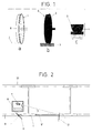
- Figures 1a, 1b and 1c are a perspective view of a wheel 1 as it appears from a lateral observation point on the inner side of rail 2
- Figure 1b shows the image 3 (graphically divided into a portion 3' corresponding to wheel 1 and a portion 3" corresponding to rail 2), as it appears from Figure 1a, acquired by an optical measurement and detection sensor positioned in the observation point
- Figure 1c shows the acquired image 4 of the outline of the tread 6 of the wheel 1 in contact with the rail 2, displayed on a display 5. It is apparent from Figure 1c that the perspective effects make the acquired image 4 substantially useless for any desired geometric-dimensional control.
- the image acquisition optical devices are amenable to change their orientation during operation, thereby varying the inclination of the optical axes by means of said tracking centring system, whose driving members should be synchronised with extremely high accuracy with the movement of the running wheel. This degrades the reliability of the measurements and entails an increase in the frequency of the instrument calibration operations, thereby making the geometric-dimensional control method particularly complex.
- an optical system for automatic geometric-dimensional inspection and control of the wheels of railway vehicles comprising a pair of rails on which a railway vehicle runs, at least one rail of said rail pair including at least one special segment with reduced cross-section, said optical system further comprising at least one optical assembly including an optical device for acquisition of two-dimensional and/or three-dimensional images, a light source emitting a light beam, a first mirror and a second mirror having corresponding optical axes, said optical device being positioned inside or outside of said wheel pair at a first fixed distance, said light source being positioned inside or outside of said wheel pair at a second fixed distance, during the control operation being effected on a wheel running on said at least one special segment, said first mirror relaying the light beam coming from said light source along a direction parallel to the corresponding rail and said second mirror relaying the light beam coming from the first mirror toward said optical device, each of said first mirror and second mirror being provided with a movement device that displaces it from the path of the wheels in synchronism with the passage of
- said optical device for acquisition of two-dimensional and/or three-dimensional images is a matrix TV camera and even more preferably a matrix TV camera implemented in charge transfer technology or Charge Coupled Device (CCD) technology.
- CCD Charge Coupled Device
- said light source can be a light plane illuminator preferably an illuminator with parallel light.
- At least one special segment of the corresponding rail can have a reduced cross-section so as to expose the inner portion and/or the outer portion of the wheel in contact therewith.
- said movement device is actuated by means of a mechanical control and/or an electronic control operated by said wheel.
- said mechanical control can be a mechanical lever and/or a cam.
- said electronic control can comprise a proximity sensor and/or a photocell that drive an electric or hydraulic or pneumatic actuator.
- the electronic system also comprises at least one electronic data processing unit that manages the images acquired by said optical device and/or manages the optical system.
- said at least one electronic data processing unit can receive the position information concerning the position of the wheel from suitable sensors, preferably proximity sensors and /or photocells, and it can correct the dimensions of the images acquired by said optical device as a function of the position of said wheel.
- said at least one electronic data processing unit receives information concerning the movement speed of said wheel from speed detection devices.
- said at least one electronic data processing unit is adapted to perform data interpolation methods in order to establish the wheel position based upon the information concerning the movement speed of said wheel.
- said optical system includes a single optical assembly.
- At least one optical assembly is translated along a direction parallel to said rail pair.
- Figure 2 shows the preferred embodiment of an optical system for automatic geometric-dimensional control according to this invention during acquisition of the image of wheel 1 to be monitored.
- the system comprises a matrix TV camera 7, preferably implemented in a charge transfer technology or CCD (Charge Coupling Device) and a light plane illuminator 8, preferably with parallel light.
- TV camera 7 and illuminator 8 are positioned between the two rails 9 and 10.
- a first mirror 11 relays the light beam coming from illuminator 8 along the path of wheel 1, namely in a direction parallel to rail 9 upon which said wheel 1 runs.
- a second mirror 12 relays the light beam coming from the first mirror 11 toward TV camera 7 that consequently is enabled to acquire by contrast the image of the wheel 1 to be monitored.
- the assembly of illuminator 8, first mirror 11, second mirror 12 and TV camera 7 forms an optical path in which the image of the outline of said wheel 1, as acquired by said TV camera 7, is always aligned with the movement direction of the wheel itself.
- the rail 9 on which wheel 1 to be controlled is runned comprises, between the first mirror 11 and the second mirror 12, a special segment 9' having a restricted section so as to leave the tread outline inner portion 13 of the wheel 1 contacting the special segment 9' of said rail 9 in exposed condition.
- the optical system according to this invention further comprises, for each of said two mirrors 11 and 12, a movement device, not shown, which automatically and rapidly displaces the corresponding mirror in synchronism with the passage of wheel 1.
- said movement device displaces the corresponding mirror in the plane of the mirror itself, without varying the orientation of the optical axis with respect to the wheel 1, to the illuminator 8 and to TV camera 7, not even in the presence of vibrations in the movement plane.
- the movement device can be actuated by means of a mechanical control, such as a mechanical lever and/or a cam operated by wheel 1 , and/or an electronic control, such as a proximity sensor and/or a photoelectric cell, which detect the passage of wheel 1 and drive an electric, pneumatic or hydraulic actuator. Should an electronic control and a mechanical control be contemporaneously present, the latter acts as a safety control to remedy the possible failure of the first one.
- the optical system according to this invention also comprises an electronic data processing unit, not shown, adapted to construe the images acquired by said TV camera 7 and to manage all components of the whole system.
- Figure 3a shows a view axially aligned with the movement direction of the wheel 1 running on said special segment 9' of rail 9.
- Figure 3b shows the image 14 that can be acquired by an optical sensor device, such as the TV camera 7; in particular, the image 14 is graphically divided into a portion 14' corresponding to wheel 1 and a portion 14" corresponding to said special segment 9' of rail 9.
- Figure 3c shows the image 15 acquired by the TV camera 7, as displayed on a display 5, corresponding to the outline of tread 6 of wheel 1 contacting the special. segment 9' of said rail 9.
- Figure 3c clearly evidences that the inner portion 13 of the tread outline of wheel 1 is completely visible and exploitable for geometric-dimensional control of the wheel 1.
- the electronic data processing unit of the optical system according to this invention is adapted to correct such dimension variation of the acquired images by keeping the variable scale coefficients between the various images into account, on the base of the corresponding positions of the wheel 1.
- the information regarding the position of wheel 1 in the special segment 9' of the rail 9 can be furnished to the electronic data processing unit by suitable sensors, not shown, which the optical system according to this invention is provided with.
- position sensors are conventional photocell and/or proximity sensors.
- the electronic data processing unit could also receive information concerning the advancement speed of the wheel 1 and perform data interpolation methods in order to ascertain the position of the wheel 1 in some portions of the special segment 9' of the rail 9.
- the electronic data processing unit is adapted to calculate the scale coefficients as a function of the position of the wheel 1, so as to permit correcting the dimensions of the images acquired by the TV camera 7 and obtaining the real dimensions of the outline of the tread 6 of the wheel 1 in contact with the special segment 9' of the rail 9.
- the matrix TV camera 7 can be substituted by a different optical device adapted to acquire two-dimensional and /or three-dimensional images.
- the TV camera 7 and the illuminator 8 can also be positioned outside of the rail pair 9 and 10 or be positioned on different sides of the rail 9.
- FIG. 10 Further embodiments of the optical system according to this invention, can be provided with a second optical component assembly comprising a second TV camera, a second illuminator and a second mirror pair, adapted to perform similar geometric-dimensional inspection and control functions on the wheels running on the other rail 10.
- a second optical component assembly comprising a second TV camera, a second illuminator and a second mirror pair, adapted to perform similar geometric-dimensional inspection and control functions on the wheels running on the other rail 10.
- provisions can be made for more than one optical assembly operating on the same rail 9 or 10, particularly in those cases in which the interaxial distance between two consecutive wheels is smaller than the circumference of the wheels, thereby inhibiting the possibility to perform the inspection and control function over the whole circumference with a single optical assembly.
- FIG. 9 An illustration of an embodiment of the system according to this invention.
- rail 9 could be provided with two reduced cross-section special segments in order to expose the inner portion and the outer portion, respectively, of the tread outline of said wheel 1.
- Still further embodiments of the optical system according to this invention can provide for the TV camera 7, the illuminator 8 and the two mirrors 11 and 12 to be integrally translated along the movement direction of wheel 1, particularly in those cases in which the interaxial distance between two consecutive wheels is smaller than the circumference of the wheels.
- the automatic geometric-dimensional inspection and control optical system according to this invention can be arranged on a conventional railway line and, therefore, the control function can be exploited in reliable, simple, rapid and inexpensive way, at a frequency much higher than the minimum frequency established by the presently adopted maintainment schedules.
- An advantage that can be obtained by exploiting the optical system according to this invention is connected with the substantial elimination of the cumbersome perspective effects that occur in the acquisition of images always in alignment with the movement direction of the wheel to be controlled.
- a further advantage offered by the optical system according to this invention with respect to the conventional apparatuses is to be observed in that the two mirrors 11 and 12 are moved along the optical path during the passage of the wheel in the plane of the mirrors themselves, with the orientation of the optical axes remaining constant even in the presence of vibrations in the movement plane, whilst said mirrors remain substantially stationary and stable during the acquisition of the images, thereby eliminating the need of a continuous alignment operation.
- the optical system performs the correction of the dimensions of the image acquired while the wheel position varies, thereby furnishing a correct measure of the real dimensions of the wheel.
Landscapes
- Physics & Mathematics (AREA)
- General Physics & Mathematics (AREA)
- Length Measuring Devices By Optical Means (AREA)
- Machines For Laying And Maintaining Railways (AREA)
- Investigating Materials By The Use Of Optical Means Adapted For Particular Applications (AREA)
- Length Measuring Devices With Unspecified Measuring Means (AREA)
Abstract
Description
Claims (17)
- An optical system for automatic geometric-dimensional inspection and control of the wheels of railway vehicles comprising a pair of rails (9, 10) on which a railway vehicle runs, at least a rail (9) of said rail pair (9, 10) including at least one special segment (9') with reduced cross-section, said optical system further comprising at least one optical assembly including an optical device (7) for acquisition of two-dimensional and/or three-dimensional images, a light source (8) emitting a light beam, a first mirror (11) and a second mirror (12) having corresponding optical axes, said optical device (7) being positioned inside or outside of said wheel pair (9, 10) at a first fixed distance, said light source being positioned inside or outside of said wheel pair (9, 10) at a second fixed distance, during the control operation being effected on a wheel running on said at least one special segment (9'), said first mirror (11) relaying the light beam coming from said light source (8) along a direction parallel to the corresponding rail (9) and said second mirror (12) relaying the light beam coming from the first mirror (11) toward said optical device (7), each of said first mirror (11) and second mirror (12) being provided with a movement device that displaces it from the path of the wheels (1) in synchronism with the passage of a wheel (1) while the orientation of the corresponding optical axis with respect to the wheel (1), to the optical device (7) and to the light source (8) is maintained constant.
- An optical system according to claim 1, characterised in that said optical device for acquisition of two-dimensional and/or three-dimensional images is a matrix TV camera (7).
- An optical system according to claim 2, characterised in that said matrix TV camera (7) is a matrix TV camera implemented in charge transfer technology or Charge Coupled Device (CCD) technology.
- An optical system according to any one of the preceding claims, characterised in that said light source is a light plane illuminator (8).
- An optical system according to claim 4, characterised in that said illuminator (8) is an illuminator with parallel light.
- An optical system according to any one of the preceding claims, characterised in that at least one special segment (9') of the corresponding rail (9) has a reduced cross-section so as to expose the inner portion (13) and/or the outer portion of the wheel (1) in contact therewith.
- An optical system according to any one of the preceding claims, characterised in that said movement device is actuated by means of a mechanical control and/or an electronic control operated by said wheel (1).
- An optical system according to claim 7, characterised in that said mechanical control is a mechanical lever and/or a cam.
- An optical system according to claim 7 or 8, characterised in that said electronic control comprises a proximity sensor and/or a photocell that drive an electric or hydraulic or pneumatic actuator.
- An optical system according to any one of the preceding claims, characterised in that it further comprises at least one electronic data processing unit that manages the images acquired by said optical device (7) and/or manages the optical system.
- An optical system according to claim 10, characterised in that said at least one electronic data processing unit receives the position information concerning the position of the wheel (1) from suitable sensors and corrects the dimensions of the images acquired by said optical device (7) as a function of the position of said wheel (1).
- An optical system according to claim 11, characterised in that said position sensors that detect the position of the wheel (1) are proximity sensors and /or photocells.
- An optical system according to claim 10 or 11, characterised in that said at least one electronic data processing unit receives information concerning the movement speed of said wheel (1) from speed detection devices.
- An optical system according to claim 13, characterised in that said at least one electronic data processing unit performs data interpolation methods in order to establish the wheel position based upon the information concerning the movement speed of said wheel (1).
- An optical system according to any one of the preceding claims, characterised in that it includes a single optical assembly.
- An optical system according to any one of the preceding claims, characterised in that at least one optical assembly is translated along a direction parallel to said rail pair (9, 10).
- An optical system for automatic geometric-dimensional inspection and control of the wheels of railway vehicles according to any one of the preceding claims, substantially as described and shown.
Applications Claiming Priority (2)
| Application Number | Priority Date | Filing Date | Title |
|---|---|---|---|
| IT2000RM000029A IT1315804B1 (en) | 2000-01-19 | 2000-01-19 | AUTOMATIC GEOMETRIC-DIMENSIONAL INSPECTION AND CONTROL SYSTEM FOR WHEELS OF RAILWAY VEHICLES. |
| ITRM000029 | 2000-01-19 |
Publications (3)
| Publication Number | Publication Date |
|---|---|
| EP1118834A2 true EP1118834A2 (en) | 2001-07-25 |
| EP1118834A3 EP1118834A3 (en) | 2003-02-05 |
| EP1118834B1 EP1118834B1 (en) | 2006-04-05 |
Family
ID=11454360
Family Applications (1)
| Application Number | Title | Priority Date | Filing Date |
|---|---|---|---|
| EP01830013A Expired - Lifetime EP1118834B1 (en) | 2000-01-19 | 2001-01-12 | Device to optically measure the wheels of railway vehicles |
Country Status (5)
| Country | Link |
|---|---|
| EP (1) | EP1118834B1 (en) |
| AT (1) | ATE322666T1 (en) |
| DE (1) | DE60118446T2 (en) |
| ES (1) | ES2260186T3 (en) |
| IT (1) | IT1315804B1 (en) |
Cited By (8)
| Publication number | Priority date | Publication date | Assignee | Title |
|---|---|---|---|---|
| EP1324005A3 (en) * | 2001-12-03 | 2005-09-14 | Patentes Talgo, S.A. | Device and process for measuring ovalization, buckling, planes and rolling parameters of railway wheels |
| RU2466046C1 (en) * | 2011-03-02 | 2012-11-10 | Владимир Семенович Потапенко | Method of diagnosing position of mounted axle in operated passenger and freight car bogie frame |
| CN102840988A (en) * | 2012-10-12 | 2012-12-26 | 株洲南车时代电气股份有限公司 | Positioning method for locomotive wheel and rolling test bed track wheel |
| CN109283187A (en) * | 2018-10-12 | 2019-01-29 | 成都精工华耀科技有限公司 | A kind of lightweight track two dimension and three-dimensional fusion imaging system |
| IT202000013051A1 (en) | 2020-06-01 | 2021-12-01 | Alessio Gellini | Device for the maintenance of railway tracks and trolleys of railway vehicles |
| IT202000013063A1 (en) | 2020-06-03 | 2021-12-03 | Alessio Gellini | Device for railway maintenance |
| IT202000013066A1 (en) | 2020-06-03 | 2021-12-03 | Alessio Gellini | Advanced railway maintenance device |
| CN114728651A (en) * | 2019-11-22 | 2022-07-08 | 法伊韦利传送器意大利有限公司 | System for determining wheel-rail adhesion values of a rail vehicle |
Families Citing this family (2)
| Publication number | Priority date | Publication date | Assignee | Title |
|---|---|---|---|---|
| SG10201911740SA (en) | 2018-12-06 | 2020-07-29 | Ensco Inc | Systems and methods for analyzing a rail |
| CN114459369B (en) * | 2022-03-11 | 2023-05-12 | 浙江师范大学 | Train wheel set conveying and wheel diameter measuring integrated equipment and detection method |
Family Cites Families (7)
| Publication number | Priority date | Publication date | Assignee | Title |
|---|---|---|---|---|
| DE3526923A1 (en) * | 1985-07-27 | 1987-02-05 | Man Technologie Gmbh | METHOD AND DEVICE FOR CONTACTLESS DETERMINATION OF SURFACES |
| EP0212052B1 (en) * | 1985-08-12 | 1992-10-21 | Wilhelm Hegenscheidt Gesellschaft mbH | Device for measurement of wheels of wheel sets integrated in the vehicle |
| DK183089D0 (en) * | 1989-04-14 | 1989-04-14 | Oedegaard & Danneskiold Samsoe | INSTALLATION FOR TRACK-BASED MEASUREMENT OF THE WHEEL PROFILE ON J ERBANE WHEELS |
| DE3912544A1 (en) * | 1989-04-17 | 1990-10-18 | Drewell Paul Drello Gmbh | Generation of light reflecting background - forming cloud of reflecting gas or vapour e.g. for investigating rail vehicle wheels |
| US5636026A (en) * | 1995-03-16 | 1997-06-03 | International Electronic Machines Corporation | Method and system for contactless measurement of railroad wheel characteristics |
| ES2122876B1 (en) * | 1995-06-29 | 1999-08-01 | Talgo Patentes | INSTALLATION AND MEASURING PROCEDURE OF ROLLING PARAMETERS BY ARTIFICIAL VISION IN WHEELS OF RAILWAY VEHICLES. |
| US5793492A (en) * | 1997-01-24 | 1998-08-11 | Loram Maintenance Of Way, Inc. | Wheel profile sensor |
-
2000
- 2000-01-19 IT IT2000RM000029A patent/IT1315804B1/en active
-
2001
- 2001-01-12 DE DE60118446T patent/DE60118446T2/en not_active Expired - Lifetime
- 2001-01-12 AT AT01830013T patent/ATE322666T1/en not_active IP Right Cessation
- 2001-01-12 ES ES01830013T patent/ES2260186T3/en not_active Expired - Lifetime
- 2001-01-12 EP EP01830013A patent/EP1118834B1/en not_active Expired - Lifetime
Cited By (8)
| Publication number | Priority date | Publication date | Assignee | Title |
|---|---|---|---|---|
| EP1324005A3 (en) * | 2001-12-03 | 2005-09-14 | Patentes Talgo, S.A. | Device and process for measuring ovalization, buckling, planes and rolling parameters of railway wheels |
| RU2466046C1 (en) * | 2011-03-02 | 2012-11-10 | Владимир Семенович Потапенко | Method of diagnosing position of mounted axle in operated passenger and freight car bogie frame |
| CN102840988A (en) * | 2012-10-12 | 2012-12-26 | 株洲南车时代电气股份有限公司 | Positioning method for locomotive wheel and rolling test bed track wheel |
| CN109283187A (en) * | 2018-10-12 | 2019-01-29 | 成都精工华耀科技有限公司 | A kind of lightweight track two dimension and three-dimensional fusion imaging system |
| CN114728651A (en) * | 2019-11-22 | 2022-07-08 | 法伊韦利传送器意大利有限公司 | System for determining wheel-rail adhesion values of a rail vehicle |
| IT202000013051A1 (en) | 2020-06-01 | 2021-12-01 | Alessio Gellini | Device for the maintenance of railway tracks and trolleys of railway vehicles |
| IT202000013063A1 (en) | 2020-06-03 | 2021-12-03 | Alessio Gellini | Device for railway maintenance |
| IT202000013066A1 (en) | 2020-06-03 | 2021-12-03 | Alessio Gellini | Advanced railway maintenance device |
Also Published As
| Publication number | Publication date |
|---|---|
| ATE322666T1 (en) | 2006-04-15 |
| DE60118446T2 (en) | 2006-11-09 |
| EP1118834A3 (en) | 2003-02-05 |
| ES2260186T3 (en) | 2006-11-01 |
| ITRM20000029A0 (en) | 2000-01-19 |
| EP1118834B1 (en) | 2006-04-05 |
| ITRM20000029A1 (en) | 2001-07-19 |
| DE60118446D1 (en) | 2006-05-18 |
| IT1315804B1 (en) | 2003-03-26 |
Similar Documents
| Publication | Publication Date | Title |
|---|---|---|
| CN100494882C (en) | Image processing-based wear measurement device for trolley wires | |
| CN1224823C (en) | Equipment for monitoring rails on a railway or tramway line | |
| JP5305603B2 (en) | Railway rail fastening bolt looseness inspection device | |
| EP1118834B1 (en) | Device to optically measure the wheels of railway vehicles | |
| EP3295158B1 (en) | System and method for the video inspection of a pantograph along an overhead contact line | |
| US7659972B2 (en) | Rail measurement system | |
| SK283974B6 (en) | Installation and process for measuring rolling parameters by means of artificial vision on wheels of railway vehicles | |
| EP2553661B1 (en) | A method and a system to detect and to determine geometrical, dimensional and positional features of products transported by a continuous conveyor, particularly of raw, roughly shaped, roughed or half-finished steel products | |
| US20120300060A1 (en) | Vision system for imaging and measuring rail deflection | |
| US20060274930A1 (en) | Vision system and a method for scanning a traveling surface to detect surface defects thereof | |
| EP1348931A2 (en) | Rolling and lathing parameter measuring device by artificial viewing for railway vehicles wheels | |
| CN107560545B (en) | Contact line abrasion automatic measuring instrument and measuring method based on machine vision | |
| EP2485010B1 (en) | Method for measuring a rail profile by optical triangulation and corresponding measuring system | |
| CN104412578B (en) | Method and apparatus for the vehicle bottom for checking motor vehicles | |
| CN102060037A (en) | Online dynamic detection device of all-periphery contour dimension of locomotive wheel pair | |
| CA2644006A1 (en) | Systems and methods for obtaining improved accuracy measurements of moving rolling stock components | |
| KR101924276B1 (en) | A System for Investing a Wheel and a Bearing of a Train | |
| RU2002117054A (en) | DEVICE AND METHOD FOR MEASURING PARAMETERS OF DEVIATION FROM THE ROUND SHAPE, BOWING, PLANE AND ROLLING OF RAILWAYS | |
| JPH09101122A (en) | Wheel shape measuring device and method | |
| CN102812326B (en) | For the method for control survey system and the measuring system for implementing described method | |
| JPH1019523A (en) | Measurement device for tread brakes | |
| JPH08178624A (en) | Trolley wire height / deviation measuring device | |
| JP2001097212A (en) | Imaging and evaluation system | |
| CA2509076C (en) | A vision system and a method for scanning a traveling surface to detect surface defects thereof | |
| CN223449169U (en) | Quick detection device of seamless line rail displacement |
Legal Events
| Date | Code | Title | Description |
|---|---|---|---|
| PUAI | Public reference made under article 153(3) epc to a published international application that has entered the european phase |
Free format text: ORIGINAL CODE: 0009012 |
|
| AK | Designated contracting states |
Kind code of ref document: A2 Designated state(s): AT BE CH CY DE DK ES FI FR GB GR IE IT LI LU MC NL PT SE TR |
|
| AX | Request for extension of the european patent |
Free format text: AL;LT;LV;MK;RO;SI |
|
| PUAL | Search report despatched |
Free format text: ORIGINAL CODE: 0009013 |
|
| AK | Designated contracting states |
Designated state(s): AT BE CH CY DE DK ES FI FR GB GR IE IT LI LU MC NL PT SE TR |
|
| AX | Request for extension of the european patent |
Extension state: AL LT LV MK RO SI |
|
| RIC1 | Information provided on ipc code assigned before grant |
Ipc: 7G 01M 17/10 B Ipc: 7G 01B 11/10 A |
|
| 17P | Request for examination filed |
Effective date: 20030619 |
|
| AKX | Designation fees paid |
Designated state(s): AT BE CH CY DE DK ES FI FR GB GR IE IT LI LU MC NL PT SE TR |
|
| GRAP | Despatch of communication of intention to grant a patent |
Free format text: ORIGINAL CODE: EPIDOSNIGR1 |
|
| GRAS | Grant fee paid |
Free format text: ORIGINAL CODE: EPIDOSNIGR3 |
|
| GRAA | (expected) grant |
Free format text: ORIGINAL CODE: 0009210 |
|
| AK | Designated contracting states |
Kind code of ref document: B1 Designated state(s): AT BE CH CY DE DK ES FI FR GB GR IE IT LI LU MC NL PT SE TR |
|
| PG25 | Lapsed in a contracting state [announced via postgrant information from national office to epo] |
Ref country code: IT Free format text: LAPSE BECAUSE OF FAILURE TO SUBMIT A TRANSLATION OF THE DESCRIPTION OR TO PAY THE FEE WITHIN THE PRESCRIBED TIME-LIMIT;WARNING: LAPSES OF ITALIAN PATENTS WITH EFFECTIVE DATE BEFORE 2007 MAY HAVE OCCURRED AT ANY TIME BEFORE 2007. THE CORRECT EFFECTIVE DATE MAY BE DIFFERENT FROM THE ONE RECORDED. Effective date: 20060405 Ref country code: NL Free format text: LAPSE BECAUSE OF FAILURE TO SUBMIT A TRANSLATION OF THE DESCRIPTION OR TO PAY THE FEE WITHIN THE PRESCRIBED TIME-LIMIT Effective date: 20060405 Ref country code: LI Free format text: LAPSE BECAUSE OF FAILURE TO SUBMIT A TRANSLATION OF THE DESCRIPTION OR TO PAY THE FEE WITHIN THE PRESCRIBED TIME-LIMIT Effective date: 20060405 Ref country code: CH Free format text: LAPSE BECAUSE OF FAILURE TO SUBMIT A TRANSLATION OF THE DESCRIPTION OR TO PAY THE FEE WITHIN THE PRESCRIBED TIME-LIMIT Effective date: 20060405 Ref country code: BE Free format text: LAPSE BECAUSE OF FAILURE TO SUBMIT A TRANSLATION OF THE DESCRIPTION OR TO PAY THE FEE WITHIN THE PRESCRIBED TIME-LIMIT Effective date: 20060405 Ref country code: AT Free format text: LAPSE BECAUSE OF FAILURE TO SUBMIT A TRANSLATION OF THE DESCRIPTION OR TO PAY THE FEE WITHIN THE PRESCRIBED TIME-LIMIT Effective date: 20060405 Ref country code: FI Free format text: LAPSE BECAUSE OF FAILURE TO SUBMIT A TRANSLATION OF THE DESCRIPTION OR TO PAY THE FEE WITHIN THE PRESCRIBED TIME-LIMIT Effective date: 20060405 |
|
| REG | Reference to a national code |
Ref country code: GB Ref legal event code: FG4D |
|
| REG | Reference to a national code |
Ref country code: CH Ref legal event code: EP |
|
| REG | Reference to a national code |
Ref country code: IE Ref legal event code: FG4D |
|
| REF | Corresponds to: |
Ref document number: 60118446 Country of ref document: DE Date of ref document: 20060518 Kind code of ref document: P |
|
| PG25 | Lapsed in a contracting state [announced via postgrant information from national office to epo] |
Ref country code: DK Free format text: LAPSE BECAUSE OF FAILURE TO SUBMIT A TRANSLATION OF THE DESCRIPTION OR TO PAY THE FEE WITHIN THE PRESCRIBED TIME-LIMIT Effective date: 20060705 Ref country code: SE Free format text: LAPSE BECAUSE OF FAILURE TO SUBMIT A TRANSLATION OF THE DESCRIPTION OR TO PAY THE FEE WITHIN THE PRESCRIBED TIME-LIMIT Effective date: 20060705 |
|
| PG25 | Lapsed in a contracting state [announced via postgrant information from national office to epo] |
Ref country code: PT Free format text: LAPSE BECAUSE OF FAILURE TO SUBMIT A TRANSLATION OF THE DESCRIPTION OR TO PAY THE FEE WITHIN THE PRESCRIBED TIME-LIMIT Effective date: 20060905 |
|
| NLV1 | Nl: lapsed or annulled due to failure to fulfill the requirements of art. 29p and 29m of the patents act | ||
| REG | Reference to a national code |
Ref country code: CH Ref legal event code: PL |
|
| REG | Reference to a national code |
Ref country code: ES Ref legal event code: FG2A Ref document number: 2260186 Country of ref document: ES Kind code of ref document: T3 |
|
| ET | Fr: translation filed | ||
| PG25 | Lapsed in a contracting state [announced via postgrant information from national office to epo] |
Ref country code: IE Free format text: LAPSE BECAUSE OF NON-PAYMENT OF DUE FEES Effective date: 20070112 |
|
| PG25 | Lapsed in a contracting state [announced via postgrant information from national office to epo] |
Ref country code: MC Free format text: LAPSE BECAUSE OF NON-PAYMENT OF DUE FEES Effective date: 20070131 |
|
| PLBE | No opposition filed within time limit |
Free format text: ORIGINAL CODE: 0009261 |
|
| STAA | Information on the status of an ep patent application or granted ep patent |
Free format text: STATUS: NO OPPOSITION FILED WITHIN TIME LIMIT |
|
| 26N | No opposition filed |
Effective date: 20070108 |
|
| PG25 | Lapsed in a contracting state [announced via postgrant information from national office to epo] |
Ref country code: GR Free format text: LAPSE BECAUSE OF FAILURE TO SUBMIT A TRANSLATION OF THE DESCRIPTION OR TO PAY THE FEE WITHIN THE PRESCRIBED TIME-LIMIT Effective date: 20060706 |
|
| PG25 | Lapsed in a contracting state [announced via postgrant information from national office to epo] |
Ref country code: CY Free format text: LAPSE BECAUSE OF FAILURE TO SUBMIT A TRANSLATION OF THE DESCRIPTION OR TO PAY THE FEE WITHIN THE PRESCRIBED TIME-LIMIT Effective date: 20060405 Ref country code: LU Free format text: LAPSE BECAUSE OF NON-PAYMENT OF DUE FEES Effective date: 20070112 |
|
| PG25 | Lapsed in a contracting state [announced via postgrant information from national office to epo] |
Ref country code: TR Free format text: LAPSE BECAUSE OF FAILURE TO SUBMIT A TRANSLATION OF THE DESCRIPTION OR TO PAY THE FEE WITHIN THE PRESCRIBED TIME-LIMIT Effective date: 20060405 |
|
| PGFP | Annual fee paid to national office [announced via postgrant information from national office to epo] |
Ref country code: FR Payment date: 20110128 Year of fee payment: 11 |
|
| PGFP | Annual fee paid to national office [announced via postgrant information from national office to epo] |
Ref country code: DE Payment date: 20110325 Year of fee payment: 11 Ref country code: GB Payment date: 20110112 Year of fee payment: 11 Ref country code: ES Payment date: 20110216 Year of fee payment: 11 |
|
| GBPC | Gb: european patent ceased through non-payment of renewal fee |
Effective date: 20120112 |
|
| REG | Reference to a national code |
Ref country code: FR Ref legal event code: ST Effective date: 20120928 |
|
| PG25 | Lapsed in a contracting state [announced via postgrant information from national office to epo] |
Ref country code: DE Free format text: LAPSE BECAUSE OF NON-PAYMENT OF DUE FEES Effective date: 20120801 Ref country code: GB Free format text: LAPSE BECAUSE OF NON-PAYMENT OF DUE FEES Effective date: 20120112 |
|
| REG | Reference to a national code |
Ref country code: DE Ref legal event code: R119 Ref document number: 60118446 Country of ref document: DE Effective date: 20120801 |
|
| PG25 | Lapsed in a contracting state [announced via postgrant information from national office to epo] |
Ref country code: FR Free format text: LAPSE BECAUSE OF NON-PAYMENT OF DUE FEES Effective date: 20120131 |
|
| PGFP | Annual fee paid to national office [announced via postgrant information from national office to epo] |
Ref country code: IT Payment date: 20120731 Year of fee payment: 12 |
|
| REG | Reference to a national code |
Ref country code: ES Ref legal event code: FD2A Effective date: 20130705 |
|
| PG25 | Lapsed in a contracting state [announced via postgrant information from national office to epo] |
Ref country code: ES Free format text: LAPSE BECAUSE OF NON-PAYMENT OF DUE FEES Effective date: 20120113 |
|
| PG25 | Lapsed in a contracting state [announced via postgrant information from national office to epo] |
Ref country code: IT Free format text: LAPSE BECAUSE OF NON-PAYMENT OF DUE FEES Effective date: 20140112 |