EP1118814A1 - Epicycloidal light guide and illuminating facility - Google Patents
Epicycloidal light guide and illuminating facility Download PDFInfo
- Publication number
- EP1118814A1 EP1118814A1 EP00116130A EP00116130A EP1118814A1 EP 1118814 A1 EP1118814 A1 EP 1118814A1 EP 00116130 A EP00116130 A EP 00116130A EP 00116130 A EP00116130 A EP 00116130A EP 1118814 A1 EP1118814 A1 EP 1118814A1
- Authority
- EP
- European Patent Office
- Prior art keywords
- epicycloid
- light
- light guide
- guide
- cross
- Prior art date
- Legal status (The legal status is an assumption and is not a legal conclusion. Google has not performed a legal analysis and makes no representation as to the accuracy of the status listed.)
- Granted
Links
- 239000000463 material Substances 0.000 claims abstract description 10
- 230000003247 decreasing effect Effects 0.000 abstract description 9
- 230000003287 optical effect Effects 0.000 abstract description 6
- 238000004519 manufacturing process Methods 0.000 abstract description 5
- 230000002708 enhancing effect Effects 0.000 abstract 1
- 239000003518 caustics Substances 0.000 description 3
- 230000004907 flux Effects 0.000 description 3
- 230000000694 effects Effects 0.000 description 2
- 238000000034 method Methods 0.000 description 2
- 238000012986 modification Methods 0.000 description 2
- 230000004048 modification Effects 0.000 description 2
- 238000000149 argon plasma sintering Methods 0.000 description 1
- 239000012141 concentrate Substances 0.000 description 1
- 238000010276 construction Methods 0.000 description 1
- 238000005516 engineering process Methods 0.000 description 1
- 230000001902 propagating effect Effects 0.000 description 1
- 230000005855 radiation Effects 0.000 description 1
- 238000009751 slip forming Methods 0.000 description 1
- 239000010409 thin film Substances 0.000 description 1
Images



Classifications
-
- F—MECHANICAL ENGINEERING; LIGHTING; HEATING; WEAPONS; BLASTING
- F21—LIGHTING
- F21V—FUNCTIONAL FEATURES OR DETAILS OF LIGHTING DEVICES OR SYSTEMS THEREOF; STRUCTURAL COMBINATIONS OF LIGHTING DEVICES WITH OTHER ARTICLES, NOT OTHERWISE PROVIDED FOR
- F21V7/00—Reflectors for light sources
- F21V7/04—Optical design
-
- G—PHYSICS
- G02—OPTICS
- G02B—OPTICAL ELEMENTS, SYSTEMS OR APPARATUS
- G02B6/00—Light guides; Structural details of arrangements comprising light guides and other optical elements, e.g. couplings
- G02B6/0001—Light guides; Structural details of arrangements comprising light guides and other optical elements, e.g. couplings specially adapted for lighting devices or systems
- G02B6/0005—Light guides; Structural details of arrangements comprising light guides and other optical elements, e.g. couplings specially adapted for lighting devices or systems the light guides being of the fibre type
-
- G—PHYSICS
- G02—OPTICS
- G02B—OPTICAL ELEMENTS, SYSTEMS OR APPARATUS
- G02B6/00—Light guides; Structural details of arrangements comprising light guides and other optical elements, e.g. couplings
- G02B6/0001—Light guides; Structural details of arrangements comprising light guides and other optical elements, e.g. couplings specially adapted for lighting devices or systems
- G02B6/0096—Light guides; Structural details of arrangements comprising light guides and other optical elements, e.g. couplings specially adapted for lighting devices or systems the lights guides being of the hollow type
-
- F—MECHANICAL ENGINEERING; LIGHTING; HEATING; WEAPONS; BLASTING
- F21—LIGHTING
- F21V—FUNCTIONAL FEATURES OR DETAILS OF LIGHTING DEVICES OR SYSTEMS THEREOF; STRUCTURAL COMBINATIONS OF LIGHTING DEVICES WITH OTHER ARTICLES, NOT OTHERWISE PROVIDED FOR
- F21V2200/00—Use of light guides, e.g. fibre optic devices, in lighting devices or systems
- F21V2200/10—Use of light guides, e.g. fibre optic devices, in lighting devices or systems of light guides of the optical fibres type
-
- Y—GENERAL TAGGING OF NEW TECHNOLOGICAL DEVELOPMENTS; GENERAL TAGGING OF CROSS-SECTIONAL TECHNOLOGIES SPANNING OVER SEVERAL SECTIONS OF THE IPC; TECHNICAL SUBJECTS COVERED BY FORMER USPC CROSS-REFERENCE ART COLLECTIONS [XRACs] AND DIGESTS
- Y10—TECHNICAL SUBJECTS COVERED BY FORMER USPC
- Y10S—TECHNICAL SUBJECTS COVERED BY FORMER USPC CROSS-REFERENCE ART COLLECTIONS [XRACs] AND DIGESTS
- Y10S385/00—Optical waveguides
- Y10S385/901—Illuminating or display apparatus
Definitions
- the present invention relates to a light guide capable of transferring light from an illuminating apparatus to a certain destination, and in particular to a light guide having an epicycloid cross section of a guide.
- an illuminating apparatus having a channel shape light guide capable of redistributing light from an illuminating apparatus through a lateral surface is directing to illuminating light to a wall surface of a guide based on a light flux which is smaller than an illuminating apparatus which does not have a light guide.
- the channel shape light guide must satisfy the following condition for being effectively used for various illuminating purposes.
- a front portion of a light guide is formed in circle(having a certain convex portion) or polygonal shape for a light-related structure of a channel light guide.
- a light reflection unit having a lamp is formed in circle and is coincided with a hole of a channel type light guide.
- a circular and polygonal light guide channel is capable of effectively preventing a radiation of light through a light guide wall surface irrespective of a material used for a light guide having a mirror reflection or transparently prismatic or light scattering effect.
- a light distribution characteristic which must be changed in accordance with various applications is not changed.
- a plurality of patent technologies concerning a geometrical variation of a light split based on a length of a light guide, a modification of a light guide, and a light emission parameter are not capable of optimizing an illuminating apparatus under a required condition.
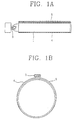
- Figures 1A and 1B illustrate the occasions that a prism is installed at a wall surface of a light guide having a circular cross section.
- a reflection cover is installed around a bulb 3 for concentrating light from the bulb 3 at a certain front portion, and a guide 1 is connected to transfer the light to a certain destination at the front surface of the reflection cover.
- a cap 2 is engaged at an end of the guide.
- Figure 1B which illustrates the cross section of the light guide, the shape of the cross section is circular, and an engaging portion 5 is formed at the upper portion of the same.
- the guide is formed of an external guide 4 and an internal guide 9.
- the inner material is formed of a structured prism.
- Figures 2A and 2B illustrate the shape of the prism. As shown in Figure 2A, an isosceles triangle is continuously formed on the prism thin film, and Figure 2 illustrates the size of the same.
- the guide using the prism is capable of full-reflecting the light inputted at a certain angle.
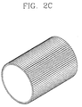
- Figure 2C is a perspective view illustrating a part of the guide having the prism.
- the epicycloid type light guide is characterized in that a cross section of the guide is formed in a pipe shape having an epicycloid curve.
- the present invention relates to an illuminating apparatus formed of a light source, an empty guide unit extended from the light source and having a transparent part.
- the present invention includes a pipe shaped light guide having a cross section having an epicycloid curve for improving a power and light emitting characteristic. A light is passed through using a certain material or prism at a certain portion of the curve epicycloid cross section, and a reflection plate of a high reflection ratio is formed at the remaining portions.
- a conical reflection plate may be installed at a certain distance from a lamp in the light guide.
- the reflection plate is formed in a conical shape and has the same number of the branches as the number of the branches of the epicycloid curve of the guide cross section.
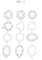
- Figure 3 illustrates various epicycloid curves. Most epicycloid curves are formed in a shape of flower leaf. Assuming that a semi-circular arc is as a branch, the number of branches is 3 through 6, and there may be more than 3 to 6 branches. Figure 3 illustrates a circular shape and ellipse epicycloid(Refer to i through I). In the present invention, the circular epicycloid having 5 branches is basically used. In a preferred embodiment of the present invention, the number of the branches and the basic type of the same may be variously changed in accordance with the purpose of use of the light guide and fabrication condition.
- the light guide having various cross sections in an epicycloid curve shape has the following conditions.
- the optical design formed of a cylindrical light guide of the epicycloid may be variously implemented.
- the hollow cylindrical channel of the light guide has a radius which forms the epicycloid, the number "m" of the epicycloid branches, various shapes based on the length L of the channel which is optically near the light entry apparatus, and a geometric parameter.
- the shape of the epicycloid may be extended or short, so that it is possible to implement a lot change in the light guide based on various variations of the material type and the parameter.
- each parameter ⁇ has a range of 0-2 ⁇ .
- each branch of the epicycloid is a cycliod
- the light which is mirror-reflected from the wall of the light guide or has an internal full reflection satisfies the above-described relationship between an incident angle and a reflection angle.
- the envelope of all normal lines with respect to a tangent line at each point of the incident beam becomes a hypocycloid and may be expressed as follows.
- Equation (2) is valid with respect to the hollow light guide which is formed based on an epicycloid combination of the branches formed at a closed curve like a Cassini's oval.
- Oval light guide is shown in Figure 3(j).
- the above-described light guide is called as a combined epicycloid light guide.
- An edge effect which causes multiple reflections of light is decreased at a usual light guide as well as a combined light guide, and an expansion of an ineffective light is decreased.
- the concentration of the reflection beam(convergence) increases a path between the reflection ways which alternately decrease the energy loss during the reflection operation. As the radius of the light guide envelope is decreased, the concentration of the reflection beam is increased.
- the propagation characteristic of the light at the epicycloid type light guide is that a concentration of the light is obtained at the caustic region of the center of the light guide.
- the envelope of the caustic region is a hypocycloid.
- all center portion beam is reflected and is inputted into a slit at the epicycloid type light guide(in particular, the number of branches is odd number) compared to the circular light guide in which most part of the center beam collide with the reflection light before it reaches the slit, so that the efficiency is increased.
- Figures 5A and 5B illustrate an embodiment of the light guide having an epicycloid curve in a cross section shape.
- a reflection cover is installed to surround a bulb for concentrating light from the bulb 3 at a front portion of the illuminating apparatus.
- a guide 1 is connected at the front surface of the reflection cover for transferring the generated light to a certain far destination.
- the cross section of the guide 1 has an epicycloid curve shape, not a circle shape.
- a jig 6 is installed at an end of the guide.
- Figure 5B illustrates a detailed cross section. In this case, an epicycloid surface 21 having five branches is formed for thereby fabricating a guide.
- a high temperature-resistant reflection plate 22 is installed at a front portion of the reflection cover compared to the conventional art.
- the reflection plate 22 is conically formed in an epicycloid type differently from the guide 1 and has five branches.
- the cross sections of the guide 1 and the reflection plate 22 are formed in an epicycloid type, so that light outputted from the illuminating apparatus is effectively transferred to a certain destination.
- an expensive lens and prism are not used for thereby decreasing the fabrication cost, so that it is possible to fabricate a high efficiency light guide.
Landscapes
- Physics & Mathematics (AREA)
- General Physics & Mathematics (AREA)
- Optics & Photonics (AREA)
- Engineering & Computer Science (AREA)
- General Engineering & Computer Science (AREA)
- Light Guides In General And Applications Therefor (AREA)
- Planar Illumination Modules (AREA)
- Non-Portable Lighting Devices Or Systems Thereof (AREA)
Abstract
Description
- The present invention relates to a light guide capable of transferring light from an illuminating apparatus to a certain destination, and in particular to a light guide having an epicycloid cross section of a guide.
- Generally, an illuminating apparatus having a channel shape light guide capable of redistributing light from an illuminating apparatus through a lateral surface is directing to illuminating light to a wall surface of a guide based on a light flux which is smaller than an illuminating apparatus which does not have a light guide. The channel shape light guide must satisfy the following condition for being effectively used for various illuminating purposes.
- 1.The distribution of a light flux emitted to a guide must provide a necessary distribution of an illuminating parameter which requires a constant property and amount for an illuminated object in a direction and angle.
- 2.The power consumption must be prevented compared to other illuminating unit.
- 3. A certain gain must be obtained compared to other technical unit in view of cost.
-
- As an illuminating apparatus having a channel type light guide, in a plurality of patents which are not actually used in all types of illuminating apparatuses, a front portion of a light guide is formed in circle(having a certain convex portion) or polygonal shape for a light-related structure of a channel light guide. A light reflection unit having a lamp is formed in circle and is coincided with a hole of a channel type light guide.
- A circular and polygonal light guide channel is capable of effectively preventing a radiation of light through a light guide wall surface irrespective of a material used for a light guide having a mirror reflection or transparently prismatic or light scattering effect. In addition, a light distribution characteristic which must be changed in accordance with various applications is not changed. A plurality of patent technologies concerning a geometrical variation of a light split based on a length of a light guide, a modification of a light guide, and a light emission parameter are not capable of optimizing an illuminating apparatus under a required condition.
- It is necessary to concentrate(compress) scattered light from a light guide at a certain portion. In order to overcome the above-described problem, a method is suggested to alternately arranging a plurality of lenses in the longitudinal direction of the light guide and changing the optical characteristic of a light guide wall.
- Figures 1A and 1B illustrate the occasions that a prism is installed at a wall surface of a light guide having a circular cross section. As shown in the structure of a light guide of Figure 1A, a reflection cover is installed around a
bulb 3 for concentrating light from thebulb 3 at a certain front portion, and aguide 1 is connected to transfer the light to a certain destination at the front surface of the reflection cover. Acap 2 is engaged at an end of the guide. As shown in Figure 1B which illustrates the cross section of the light guide, the shape of the cross section is circular, and anengaging portion 5 is formed at the upper portion of the same. The guide is formed of anexternal guide 4 and an internal guide 9. The inner material is formed of a structured prism. Figures 2A and 2B illustrate the shape of the prism. As shown in Figure 2A, an isosceles triangle is continuously formed on the prism thin film, and Figure 2 illustrates the size of the same. The guide using the prism is capable of full-reflecting the light inputted at a certain angle. Figure 2C is a perspective view illustrating a part of the guide having the prism. - However, it is impossible to basically overcome the problems of a channel type light guide by changing the optical characteristic of a light guide wall alternately arranging the lenses or using the prism. The above-described problem overcoming method may increase the cost of the channel type light guide. Therefore, the structure of the light guide channel and the optical connection with the light radiating unit must be improved.
- Accordingly, it is an object of the present invention to provide a light guide capable of increasing an efficiency and fabrication cost without using a lens or prism like the conventional light guide.
In order to achieve the above object, in the present invention, the epicycloid type light guide is characterized in that a cross section of the guide is formed in a pipe shape having an epicycloid curve. - The present invention will become better understood with reference to the accompanying drawings which are given only by way of illustration and thus are not limitative of the present invention, wherein:
- Figure 1A is a vertical cross-sectional view illustrating the construction that a prism is formed on a light guide wall surface having a circular cross section in the conventional art;
- Figure 1B is a horizontal cross-sectional view illustrating the shape of a light guide cross section of Figure 1A;
- Figure 2A is a perspective view illustrating a structure of a prism of a light guide cross section of Figure 1A;
- Figure 2B is a cross-sectional view illustrating the size of a prism of Figure 2A;
- Figure 2C is a perspective view illustrating a light guide having a prism of Figure 2A;
- Figure 3 is an illustrative view of various shapes of an epicycloidal curve;
- Figure 4 is an illustrative view of a parameter equation of an epicycloidal circular cylinder according to the present invention;
- Figure 5A is a cross-sectional view illustrating an embodiment of a light guide according to the present invention; and
- Figure 5B is a horizontal cross-sectional view illustrating a cross section of a light guide of Figure 5A.
-
- The present invention relates to an illuminating apparatus formed of a light source, an empty guide unit extended from the light source and having a transparent part. The present invention includes a pipe shaped light guide having a cross section having an epicycloid curve for improving a power and light emitting characteristic. A light is passed through using a certain material or prism at a certain portion of the curve epicycloid cross section, and a reflection plate of a high reflection ratio is formed at the remaining portions.
- In addition, A conical reflection plate may be installed at a certain distance from a lamp in the light guide. The reflection plate is formed in a conical shape and has the same number of the branches as the number of the branches of the epicycloid curve of the guide cross section.
- The epicycloid is defined as a path in which a point of a circle passes through when a certain circle is drawn around the fixed circle. Therefore, various curves are formed based on the radius of the fixed circle, and it is possible to form various curves in accordance with the size of the radius of the fixed circle and the size of the radius of the rotating circle. Assuming that the radius of the fixed circle is "a", and the radius of the rotating circle is 'b", and the angle is "t", the parameter equation of the epicycloid is as follows.
- Figure 3 illustrates various epicycloid curves. Most epicycloid curves are formed in a shape of flower leaf. Assuming that a semi-circular arc is as a branch, the number of branches is 3 through 6, and there may be more than 3 to 6 branches. Figure 3 illustrates a circular shape and ellipse epicycloid(Refer to i through I). In the present invention, the circular epicycloid having 5 branches is basically used. In a preferred embodiment of the present invention, the number of the branches and the basic type of the same may be variously changed in accordance with the purpose of use of the light guide and fabrication condition.
- The light guide having various cross sections in an epicycloid curve shape has the following conditions.
- 1) The reflection amount of the wall of the light guide channel is decreased, and the moving path of the sequential reflections is decreased.
- 2) A caustic domain is formed in a propagating direction of the light flux at the light guide, and the light is compressed in the axial direction of the channel.
- 3) The above-described
conditions - 4) The fabrication cost is decreased, and the illuminating technical characteristic and energy characteristic are improved.
-
- The above-described conditions are a major condition required for overcoming the problems of an illuminating apparatus having a conventional hollow light guide.
- The optical design formed of a cylindrical light guide of the epicycloid may be variously implemented. The hollow cylindrical channel of the light guide has a radius which forms the epicycloid, the number "m" of the epicycloid branches, various shapes based on the length L of the channel which is optically near the light entry apparatus, and a geometric parameter. The shape of the epicycloid may be extended or short, so that it is possible to implement a lot change in the light guide based on various variations of the material type and the parameter.
- In view of the technical points, it is preferred to select the decreased epicycloid which is illustrated as a point M distanced by a distance of □·r(□<1) from the center on the radius "r", not on the circle which forms the epicycloid as shown in Figure 4. The cylindrical parameter equation of the epicycloid with respect to the axis z is as follows.where each parameter □ has a range of 0-2□.

- If each branch of the epicycloid is a cycliod, the light which is mirror-reflected from the wall of the light guide or has an internal full reflection satisfies the above-described relationship between an incident angle and a reflection angle. In major features of the epicycloid type light guide, the envelope of all normal lines with respect to a tangent line at each point of the incident beam becomes a hypocycloid and may be expressed as follows.
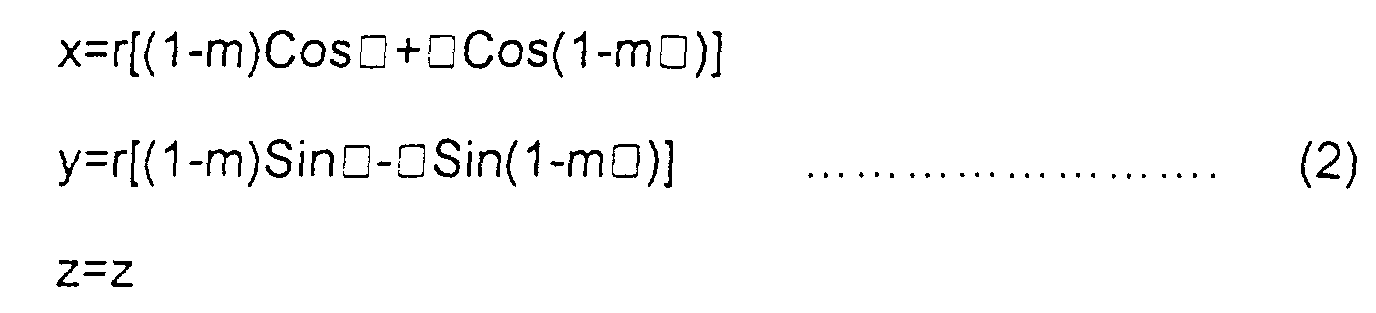
- The above-expressed Equation (2) is valid with respect to the hollow light guide which is formed based on an epicycloid combination of the branches formed at a closed curve like a Cassini's oval. Oval light guide is shown in Figure 3(j). The branches are a combination of the epicycloid wherein m=3,4,5,6,(Figure 3(l)). The above-described light guide is called as a combined epicycloid light guide. An edge effect which causes multiple reflections of light is decreased at a usual light guide as well as a combined light guide, and an expansion of an ineffective light is decreased. The concentration of the reflection beam(convergence) increases a path between the reflection ways which alternately decrease the energy loss during the reflection operation. As the radius of the light guide envelope is decreased, the concentration of the reflection beam is increased.
- The propagation characteristic of the light at the epicycloid type light guide is that a concentration of the light is obtained at the caustic region of the center of the light guide. The envelope of the caustic region is a hypocycloid. The type of the same has a similarity constant K=R/(R-2r) and is similar to the epicycloid rotated at the same center by □/K. In this case, all center portion beam is reflected and is inputted into a slit at the epicycloid type light guide(in particular, the number of branches is odd number) compared to the circular light guide in which most part of the center beam collide with the reflection light before it reaches the slit, so that the efficiency is increased.
- Figures 5A and 5B illustrate an embodiment of the light guide having an epicycloid curve in a cross section shape. As shown in Figure 5A, a reflection cover is installed to surround a bulb for concentrating light from the
bulb 3 at a front portion of the illuminating apparatus. Aguide 1 is connected at the front surface of the reflection cover for transferring the generated light to a certain far destination. The cross section of theguide 1 has an epicycloid curve shape, not a circle shape. Ajig 6 is installed at an end of the guide. Figure 5B illustrates a detailed cross section. In this case, anepicycloid surface 21 having five branches is formed for thereby fabricating a guide. At this time, the parameter equation is as follows. - Another feature of the present invention is that a high temperature-
resistant reflection plate 22 is installed at a front portion of the reflection cover compared to the conventional art. Thereflection plate 22 is conically formed in an epicycloid type differently from theguide 1 and has five branches. The parameter equation of thereflection plate 22 is as follows. - Therefore, in the present invention, since the cross sections of the
guide 1 and thereflection plate 22 are formed in an epicycloid type, so that light outputted from the illuminating apparatus is effectively transferred to a certain destination. - As described above, in the present invention, an expensive lens and prism are not used for thereby decreasing the fabrication cost, so that it is possible to fabricate a high efficiency light guide. In particular, it is possible to improve an illuminating and energy efficiency characteristic by changing the type of the epicycloid or changing an optical parameter of a material which forms the wall surface of the light guide.
- As the present invention may be embodied in several forms without departing from the spirit or essential characteristics thereof, it should also be understood that the above-described embodiment is not limited by any of the details of the foregoing description, unless otherwise specified, but rather should be construed broadly within its spirit and scope as defined in the appended claims, and therefore all changes and modifications that fall within the meets and bounds of the claims, or equivalences of such meets and bounds are therefore intended to be embraced by the appended claims.
Claims (20)
- An epicycloid type light guide which is characterized in that a cross section of the guide is formed in a pipe shape having an epicycloid curve.
- The guide of claim 1, wherein in said epicycloid, the number of branches is more than 2.
- The guide of claim 2, wherein in said epicycloid, the number of branches is 3.
- The guide of claim 2, wherein in said epicycloid, the number of branches is 4.
- The guide of claim 2, wherein in said epicycloid, the number of branches is 5.
- The guide of claim 2, wherein in said epicycloid, the number of branches is 6.
- The guide of claim 1, wherein said epicycloid curve is circular.
- The guide of claim 1, wherein said epicycloid curve is elliptical.
- The guide of claim 1, wherein light is transmitted using a light transmitting material or a prism at a portion of a cross section of the epicycloid curve, and a reflection plate formed of a high reflection ratio is installed at the remaining portions of the cross section of the same.
- An illuminating apparatus, comprising:a light source; anda pipe-shaped epicycloid guide having a transparent lateral surface and a cross section having an epicycloid curve.
- The apparatus of claim 10, wherein said a conical reflection plate is installed at a portion distanced from the light source in the light guide.
- The apparatus of claim 11, wherein said reflection plate has branches in the same number as that of the branches of the epicycloid of the guide cross section.
- The apparatus of claim 10, wherein in said epicycloid, the number of branches is more than 2.
- The apparatus of claim 13, wherein in said epicycloid, the number of branches is 3.
- The apparatus of claim 13, wherein in said epicycloid, the number of branches is 4.
- The apparatus of claim 13, wherein in said epicycloid, the number of branches is 5.
- The apparatus of claim 13, wherein in said epicycloid, the number of branches is 6.
- The apparatus of claim 10, wherein said epicycloid curve is circular.
- The apparatus of claim 10, wherein said epicycloid curve is elliptical.
- The apparatus of claim 10, wherein light is transmitted using a light transmitting material or a prism at a portion of a cross section of the epicycloid curve, and a reflection plate formed of a high reflection ratio is installed at the remaining portions of the cross section of the same.
Applications Claiming Priority (3)
| Application Number | Priority Date | Filing Date | Title |
|---|---|---|---|
| KR1020000003091A KR100356505B1 (en) | 2000-01-22 | 2000-01-22 | Epicycloidal light guide and illuminating facility |
| KR2000003091 | 2000-01-22 | ||
| KR0003091 | 2000-01-22 |
Publications (2)
| Publication Number | Publication Date |
|---|---|
| EP1118814A1 true EP1118814A1 (en) | 2001-07-25 |
| EP1118814B1 EP1118814B1 (en) | 2005-12-14 |
Family
ID=36580451
Family Applications (1)
| Application Number | Title | Priority Date | Filing Date |
|---|---|---|---|
| EP00116130A Expired - Lifetime EP1118814B1 (en) | 2000-01-22 | 2000-07-31 | Epicycloidal light guide and illuminating facility |
Country Status (7)
| Country | Link |
|---|---|
| US (1) | US6621978B1 (en) |
| EP (1) | EP1118814B1 (en) |
| JP (1) | JP3497802B2 (en) |
| KR (1) | KR100356505B1 (en) |
| DE (1) | DE60024770T2 (en) |
| RU (1) | RU2193221C2 (en) |
| UA (1) | UA65604C2 (en) |
Cited By (2)
| Publication number | Priority date | Publication date | Assignee | Title |
|---|---|---|---|---|
| WO2008029347A3 (en) * | 2006-09-08 | 2008-06-26 | Beko Elektronik Anonim Sirketi | Light guide |
| WO2013114259A1 (en) * | 2012-02-01 | 2013-08-08 | Koninklijke Philips N.V. | Method, optical system and lighting arrangement for homogenizing light |
Families Citing this family (5)
| Publication number | Priority date | Publication date | Assignee | Title |
|---|---|---|---|---|
| KR100393771B1 (en) * | 2001-03-10 | 2003-08-02 | 엘지전자 주식회사 | Lens for optical recording and reproducing system |
| US7658514B2 (en) * | 2006-04-13 | 2010-02-09 | Lg Electronics Inc. | Light guide, method and apparatus for manufacturing the same, and illuminating system having the same |
| FR2995401B1 (en) * | 2012-09-12 | 2014-09-12 | Snecma | MEASURING ROD OF EPICYCLOID SECTION |
| TWI593910B (en) * | 2014-04-24 | 2017-08-01 | Chia Lin Chen | Strip-type extended light guide lighting device |
| KR20190120844A (en) * | 2018-04-16 | 2019-10-25 | 삼성디스플레이 주식회사 | Liquid crystal display device |
Citations (1)
| Publication number | Priority date | Publication date | Assignee | Title |
|---|---|---|---|---|
| DE19640324A1 (en) * | 1996-09-19 | 1998-03-26 | Semperlux Gmbh | Prismatic light conductor channel |
Family Cites Families (8)
| Publication number | Priority date | Publication date | Assignee | Title |
|---|---|---|---|---|
| US4420740A (en) * | 1981-08-31 | 1983-12-13 | Brown Herbert L | Obstruction warning system |
| US4589729A (en) * | 1982-01-12 | 1986-05-20 | At&T Bell Laboratories | Apparatus comprising an articulated arm radiation guide |
| US4652083A (en) * | 1985-03-18 | 1987-03-24 | Laakmann Electro-Optics, Inc. | Hollow waveguide |
| IL86296A (en) * | 1988-05-06 | 1991-12-15 | Univ Ramot | Hollow fiber waveguide and method of making it |
| SU1720043A1 (en) * | 1989-06-05 | 1992-03-15 | Предприятие П/Я Р-6681 | Light flux scatterer |
| US5233679A (en) * | 1990-04-10 | 1993-08-03 | Nobuo Oyama | Striated light diffuser and method of forming the same |
| US5333090A (en) * | 1992-10-13 | 1994-07-26 | Coherent, Inc. | Optical coating for reflecting visible and longer wavelength radiation having grazing incidence angle |
| US5715347A (en) * | 1995-10-12 | 1998-02-03 | The University Of British Columbia | High efficiency prism light guide with confocal parabolic cross section |
-
2000
- 2000-01-22 KR KR1020000003091A patent/KR100356505B1/en not_active Expired - Fee Related
- 2000-07-24 RU RU2000119859/28A patent/RU2193221C2/en not_active IP Right Cessation
- 2000-07-31 DE DE60024770T patent/DE60024770T2/en not_active Expired - Fee Related
- 2000-07-31 EP EP00116130A patent/EP1118814B1/en not_active Expired - Lifetime
- 2000-07-31 JP JP2000231710A patent/JP3497802B2/en not_active Expired - Fee Related
- 2000-08-08 UA UA2000084744A patent/UA65604C2/en unknown
- 2000-10-16 US US09/688,239 patent/US6621978B1/en not_active Expired - Fee Related
Patent Citations (1)
| Publication number | Priority date | Publication date | Assignee | Title |
|---|---|---|---|---|
| DE19640324A1 (en) * | 1996-09-19 | 1998-03-26 | Semperlux Gmbh | Prismatic light conductor channel |
Cited By (4)
| Publication number | Priority date | Publication date | Assignee | Title |
|---|---|---|---|---|
| WO2008029347A3 (en) * | 2006-09-08 | 2008-06-26 | Beko Elektronik Anonim Sirketi | Light guide |
| WO2013114259A1 (en) * | 2012-02-01 | 2013-08-08 | Koninklijke Philips N.V. | Method, optical system and lighting arrangement for homogenizing light |
| CN104115046A (en) * | 2012-02-01 | 2014-10-22 | 皇家飞利浦有限公司 | Method, optical system and lighting arrangement for homogenizing light |
| CN104115046B (en) * | 2012-02-01 | 2016-05-04 | 皇家飞利浦有限公司 | For method, optical system and lighting device that light is homogenized |
Also Published As
| Publication number | Publication date |
|---|---|
| KR20010073904A (en) | 2001-08-03 |
| JP3497802B2 (en) | 2004-02-16 |
| EP1118814B1 (en) | 2005-12-14 |
| DE60024770D1 (en) | 2006-01-19 |
| RU2193221C2 (en) | 2002-11-20 |
| DE60024770T2 (en) | 2006-06-29 |
| UA65604C2 (en) | 2004-04-15 |
| JP2001215335A (en) | 2001-08-10 |
| KR100356505B1 (en) | 2002-10-31 |
| US6621978B1 (en) | 2003-09-16 |
Similar Documents
| Publication | Publication Date | Title |
|---|---|---|
| US6123436A (en) | Optical device for modifying the angular and spatial distribution of illuminating energy | |
| US6522807B2 (en) | High efficiency reflector for directing collimated light into light guides | |
| US4897771A (en) | Reflector and light system | |
| US6128431A (en) | High efficiency source coupler for optical waveguide illumination system | |
| US5481637A (en) | Hollow light guide for diffuse light | |
| EP2376830B1 (en) | Lighting device | |
| US5117312A (en) | Apparatus including concave reflectors and a line of optical fibers | |
| US20110044059A1 (en) | Light source apparatus | |
| US20060076568A1 (en) | Side-emitting optical coupling device | |
| CN211929890U (en) | Shaping laser device with encapsulation | |
| US5117478A (en) | Device for redirecting light through a hollow tubular light conduit | |
| US5217299A (en) | Reflection type lighting apparatus | |
| JP5216431B2 (en) | Strobe reflector for camera | |
| EP1118814B1 (en) | Epicycloidal light guide and illuminating facility | |
| CN105823008A (en) | Lighting device with light source and reflector of ellipsoidal reflective surface | |
| US3398274A (en) | Optically round, mechanically ovate reflector with radially stepped sections | |
| US20250297724A1 (en) | Luminaire with hollow optical systems | |
| US10737292B2 (en) | Light irradiation device and light irradiation method | |
| EP1288999A2 (en) | Double ellipsoid light bulb using total internal reflection | |
| CN110207070A (en) | Light guide member, car light and motor vehicles | |
| KR100246226B1 (en) | LCD Projector Lighting Optical System | |
| KR100417397B1 (en) | Illumination device for lcd | |
| KR20020016414A (en) | Reflector of lamp for projection display |
Legal Events
| Date | Code | Title | Description |
|---|---|---|---|
| PUAI | Public reference made under article 153(3) epc to a published international application that has entered the european phase |
Free format text: ORIGINAL CODE: 0009012 |
|
| AK | Designated contracting states |
Kind code of ref document: A1 Designated state(s): DE GB IT SE |
|
| AX | Request for extension of the european patent |
Free format text: AL;LT;LV;MK;RO;SI |
|
| 17P | Request for examination filed |
Effective date: 20010927 |
|
| AKX | Designation fees paid |
Free format text: DE GB IT SE |
|
| 17Q | First examination report despatched |
Effective date: 20040928 |
|
| GRAP | Despatch of communication of intention to grant a patent |
Free format text: ORIGINAL CODE: EPIDOSNIGR1 |
|
| GRAS | Grant fee paid |
Free format text: ORIGINAL CODE: EPIDOSNIGR3 |
|
| GRAA | (expected) grant |
Free format text: ORIGINAL CODE: 0009210 |
|
| AK | Designated contracting states |
Kind code of ref document: B1 Designated state(s): DE GB IT SE |
|
| REG | Reference to a national code |
Ref country code: GB Ref legal event code: FG4D |
|
| REF | Corresponds to: |
Ref document number: 60024770 Country of ref document: DE Date of ref document: 20060119 Kind code of ref document: P |
|
| REG | Reference to a national code |
Ref country code: SE Ref legal event code: TRGR |
|
| PLBE | No opposition filed within time limit |
Free format text: ORIGINAL CODE: 0009261 |
|
| STAA | Information on the status of an ep patent application or granted ep patent |
Free format text: STATUS: NO OPPOSITION FILED WITHIN TIME LIMIT |
|
| 26N | No opposition filed |
Effective date: 20060915 |
|
| PGFP | Annual fee paid to national office [announced via postgrant information from national office to epo] |
Ref country code: GB Payment date: 20090729 Year of fee payment: 10 Ref country code: DE Payment date: 20090723 Year of fee payment: 10 Ref country code: SE Payment date: 20090708 Year of fee payment: 10 |
|
| PGFP | Annual fee paid to national office [announced via postgrant information from national office to epo] |
Ref country code: IT Payment date: 20090725 Year of fee payment: 10 |
|
| GBPC | Gb: european patent ceased through non-payment of renewal fee |
Effective date: 20100731 |
|
| EUG | Se: european patent has lapsed | ||
| PG25 | Lapsed in a contracting state [announced via postgrant information from national office to epo] |
Ref country code: DE Free format text: LAPSE BECAUSE OF NON-PAYMENT OF DUE FEES Effective date: 20110201 |
|
| REG | Reference to a national code |
Ref country code: DE Ref legal event code: R119 Ref document number: 60024770 Country of ref document: DE Effective date: 20110201 |
|
| PG25 | Lapsed in a contracting state [announced via postgrant information from national office to epo] |
Ref country code: IT Free format text: LAPSE BECAUSE OF NON-PAYMENT OF DUE FEES Effective date: 20100731 |
|
| PG25 | Lapsed in a contracting state [announced via postgrant information from national office to epo] |
Ref country code: GB Free format text: LAPSE BECAUSE OF NON-PAYMENT OF DUE FEES Effective date: 20100731 |
|
| PG25 | Lapsed in a contracting state [announced via postgrant information from national office to epo] |
Ref country code: SE Free format text: LAPSE BECAUSE OF NON-PAYMENT OF DUE FEES Effective date: 20100801 |