EP1118478A2 - Fahrzeugeinzelradaufhängung - Google Patents
Fahrzeugeinzelradaufhängung Download PDFInfo
- Publication number
- EP1118478A2 EP1118478A2 EP00126563A EP00126563A EP1118478A2 EP 1118478 A2 EP1118478 A2 EP 1118478A2 EP 00126563 A EP00126563 A EP 00126563A EP 00126563 A EP00126563 A EP 00126563A EP 1118478 A2 EP1118478 A2 EP 1118478A2
- Authority
- EP
- European Patent Office
- Prior art keywords
- trailing arm
- vehicle
- wheel suspension
- arm section
- suspension according
- Prior art date
- Legal status (The legal status is an assumption and is not a legal conclusion. Google has not performed a legal analysis and makes no representation as to the accuracy of the status listed.)
- Withdrawn
Links
- 239000000725 suspension Substances 0.000 title claims abstract description 36
- 238000005452 bending Methods 0.000 abstract description 4
- 230000008878 coupling Effects 0.000 description 7
- 238000010168 coupling process Methods 0.000 description 7
- 238000005859 coupling reaction Methods 0.000 description 7
- 239000002184 metal Substances 0.000 description 3
- 229910052751 metal Inorganic materials 0.000 description 3
- 230000000694 effects Effects 0.000 description 2
- 238000004519 manufacturing process Methods 0.000 description 2
- 241001247986 Calotropis procera Species 0.000 description 1
- 230000001154 acute effect Effects 0.000 description 1
- 230000005540 biological transmission Effects 0.000 description 1
- 238000005266 casting Methods 0.000 description 1
- 238000010276 construction Methods 0.000 description 1
- 238000009434 installation Methods 0.000 description 1
- 230000000717 retained effect Effects 0.000 description 1
- 230000006641 stabilisation Effects 0.000 description 1
- 238000011105 stabilization Methods 0.000 description 1
Images


Classifications
-
- B—PERFORMING OPERATIONS; TRANSPORTING
- B60—VEHICLES IN GENERAL
- B60G—VEHICLE SUSPENSION ARRANGEMENTS
- B60G7/00—Pivoted suspension arms; Accessories thereof
- B60G7/001—Suspension arms, e.g. constructional features
-
- B—PERFORMING OPERATIONS; TRANSPORTING
- B60—VEHICLES IN GENERAL
- B60G—VEHICLE SUSPENSION ARRANGEMENTS
- B60G3/00—Resilient suspensions for a single wheel
- B60G3/18—Resilient suspensions for a single wheel with two or more pivoted arms, e.g. parallelogram
- B60G3/20—Resilient suspensions for a single wheel with two or more pivoted arms, e.g. parallelogram all arms being rigid
- B60G3/202—Resilient suspensions for a single wheel with two or more pivoted arms, e.g. parallelogram all arms being rigid having one longitudinal arm and two parallel transversal arms, e.g. dual-link type strut suspension
Definitions
- the invention relates to a vehicle independent wheel suspension, comprising a trailing arm a wheel bearing, which has a first, front end via an elastic bearing is pivotally supported on a vehicle body, and a wishbone that in predominantly vertical alignment to support a fall torque on at least two spaced apart points along an axis connected to the trailing arm is.
- Such wheel suspensions are particularly suitable for the suspension of the rear wheels of Passenger cars.
- EP 0 691 225 A1 discloses a wheel-guiding trailing arm, which is firmly connected to a wheel carrier, the trailing arm with its front End is pivotally coupled to a vehicle body via an elastic bearing.
- the Trailing arm is designed to be rigid and torsionally rigid.
- a wishbone is over two spaced rubber-metal bearings coupled to the wheel carrier.
- the wishbone is coupled to the wheel carrier Use of a hinge joint with a substantially vertical direction extending pivot axis.
- This independent suspension already enables one compact design and allows targeted adjustment of the self-steering behavior when Braking or when cornering due to a desired toe-in, for example, by interpreting the compliance of the handlebars.
- the desired toe-in can be influenced, for example, by a uneven suspension of the trailing arms of an axle undesirable track influences and thus undesirable self-steering effects occur.
- DE 1 430 793 A describes a further independent wheel suspension for a driven one Known rear axle, in which the support of a wheel via a wheel bearing directly on a trailing arm, which with the interposition of an elastic Rubber element is mounted on a vehicle body.
- the trailing arm torsionally elastic and flexible in the transverse direction. Coupling one Wishbone is made via a joint that is located below the wheel bearing and whose axis of rotation is arranged essentially horizontally. A fall moment support is not possible, so that additional handlebars are necessary.
- the Connection of the wishbone to the trailing arm relatively much space.
- a motor vehicle rear axle is known in which turn and torsionally rigid trailing arms are used. These trailing arms are coupled at their rear end via a common wishbone and supported by this in relation to a vehicle body, in order to produce longitudinal springs the rear wheels to reduce unwanted self-steering movements.
- the coupling of the Wishbones among each other means a complicated support against that Vehicle body that takes up a relatively large amount of space and the vehicle weight elevated.
- the trailing link is connected to the wishbone via a joint with a substantially vertical pivot axis.
- the invention is based on the object of an independent suspension create with a compact design a high driving comfort while maintaining a toe-in setting adjusted according to the situation.
- This task is performed by a vehicle single wheel suspension of the type mentioned solved, in which the trailing arm is flexible in the transverse direction, but in the vertical direction is rigid, and is further articulated to a tie rod that is in turn supported with another end on the vehicle body.
- the tie rod for compliance with a desired toe-in change, for example when braking, ensures suppresses unwanted track changes due to suspension effects.
- the solution according to the invention characterized by a high spatial compactness, since both the Trailing arms, the wishbones as well as the tie rod are kept comparatively short can.
- control arm is hinge-like on the Trailing arm attached.
- the hinge-like design allows a Reduction of the squeeze of the vehicle-side bearings of the handlebars.
- the wishbone is preferably firmly connected to the trailing arm, the elasticity the connection from the constructive geometric design of the connection point results.
- the wishbone and the trailing arm can be together be welded so that both can be prefabricated as a unit and the Installation effort remains low.
- this has one substantially vertically extending hinge column, of which a first Trailing arm section forward in the direction of travel and a second trailing arm section too the tie rod extends, the first trailing arm portion being flexible in the transverse direction and is designed to be rigid in the vertical direction.
- This can be used in the area of the tie rod Tracking a rigid configuration can be maintained without this a spring of the trailing arm leads to an undesirable toe-in change.
- the Flexibility is essentially due to the fact that causes first trailing arm section.
- the second trailing arm section can also in a hinge-near region of the first trailing arm section can be integrated.
- both trailing arm sections are as triangular wings formed with a long side in a substantially vertical Alignment connected to the hinge pillar, with the first, front Trailing arm section with its pointed end is supported on the vehicle side and the second Trailing arm section is mounted at one end of the tie rod. So that remains Space required for the trailing arm in the transverse direction of the wheel axle in question extremely low.
- the production can take place, for example, as a welded part the triangular wings are each designed as easily stampable sheet metal parts.
- the wishbone is preferred as a triangular wing with im substantially constant wall thickness formed on one long side with the Hinge column is connected and is supported at its tip end on the vehicle side.
- the Wall thickness of the wishbone which is rigid in both the transverse and vertical directions a multiple, at least twice, the wall thickness of the first Trailing arm section.
- the second Trailing arm section shorter in the direction of travel than the first trailing arm section.
- tie rod connection lying more rigid than the first trailing arm section, which consequently has a large deformation potential to compensate for an undesirable Has toe change.
- the wheel bearing is preferably behind the hinge pillar with respect to the direction of travel arranged.
- the transverse deformation potential of the side member at Longitudinal springs of the same can be optimally used.
- the pivot axis of the tie rod bearing of the trailing arm is in a further preferred Design essentially horizontal and oriented in the direction of travel. At a Longitudinal suspension with a large amplitude can thus the toe-in of the concerned Vehicle wheel are held in the desired position, while a vertical Springs of the wheel is possible and remains essentially without influence on the toe-in.
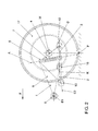
- the first embodiment shows a vehicle wheel suspension using the example of a Independent suspension of a rear wheel 17 for a passenger car.
- a trailing arm 1 is provided, on which a Wheel bearing 4 for the rear wheel 17 directly and without the interposition of another Wheel carrier is coupled.
- the rear wheel is 17th not powered.
- the rear wheel 17 can also be driven by for example, an additional gimbal coupled to a drive train Drive shaft is mounted in the wheel bearing 4.
- the trailing arm 1 is at one end with its front end in the direction of travel F. Section of a vehicle body via an elastic intermediate member, for example a Rubber bearing in the form of a rubber bush, pivoted about an axis E1.
- the Axis E1 runs horizontally slightly below the height of the wheel center axis M and transverse to Direction of travel F.
- a wishbone 2 acts on the trailing arm 1, which also has a elastic intermediate member, which in turn can be a rubber bearing around an axis E2 is pivotally mounted on a further section of the vehicle body.
- the axis E2 runs essentially in the direction of travel F. It is somewhat downward in the direction of travel F and inclined to the wheel side.
- the trailing arm 1 is with a essentially horizontally extending tie rod 3 coupled, which in turn against the vehicle body is supported.
- an elastic intermediate member for example in the form of a Rubber bushing provided that a pivotable articulation around the in Figures 1 to 3 shown axes D and K allowed.
- the trailing arm 1 has a substantially vertically extending hinge column 5 on, which is formed in the first embodiment as a hollow shaft.
- the rear, second trailing arm section 7 is in the direction of travel F shorter than the first trailing arm section 6. In the illustrated embodiment the length of the second trailing arm section 7 is less than half the length of the first trailing arm section 6.
- both trailing arm sections 6 and 7 each as a triangular wing, each with the same, but here with each other different wall thickness.
- the second trailing arm section 7 is thicker than that first trailing arm section 6. Close the upright, triangular wings each with a long side in a substantially vertical orientation to the hinge pillar 5 to ensure not only power but also moment support.
- the front trailing arm section 6 is on the vehicle side with its pointed end supported, whereas the second trailing arm section 7 at one end of the tie rod 3 is stored.
- a bushing 8 is provided on the front, first trailing arm section 6 a through opening 9 is provided concentrically with the axis E1, which already corresponds to the interacts mentioned elastic intermediate member.
- the rear, second Trailing arm section 7, however, is in a bushing 12 provided on the tie rod 3 or stored in their through opening 13.
- the rear, second trailing arm section 7 is both in the transverse direction and in Vertical direction rigid.
- the first trailing arm section 6 is in Transversely flexible and only rigid in the vertical direction, for example in that it has a significantly smaller wall thickness than the second Trailing arm section 7. This results in a rigid structure in the area of the wheel bearing 4 Guide the rear wheel 17 created with a predetermined toe-in, which Direction of travel F is flexible on a vehicle body by an essentially horizontal axis E1 is pivotally mounted, the first trailing arm section 6 in Transverse direction in the manner of a diaphragm spring or leaf spring acts.
- the mentioned wishbone 2 which in a predominantly vertical orientation to support a Falling moment along a straight line or hinge axis A with the trailing arm 1 connected is.
- the coupling takes place on the hinge column 5 between the first Trailing arm section 6 and the second trailing arm section 7, being in a view from above the wishbone 2 with the first trailing arm section 6 an angle of less than 90 degrees, preferably includes an angle in a range of 60 to 80 degrees.
- the second trailing arm section 6 lies essentially in a common plane with the first trailing arm section 7.
- the hinge axis A when viewed from the top down, slightly on the wheel side and against the Direction F inclined.
- the hinge axis A intersects the surface of a roadway in Driving direction F in front of or at the level of the wheel contact point P. Consequently, this is here Wheel bearing 4 with respect to the direction of travel F behind the hinge pillar 5 and in particular arranged behind the hinge axis A.
- the wishbone 2 is also as triangular wing with constant wall thickness, one with a long side is connected to the hinge pillar 5 and at its tip end on the vehicle side is pivotally supported.
- the wishbone 2 has one at its pointed end Bushing 10 with a through opening 11, which with the already mentioned elastic Intermediate element cooperates for vehicle-side support.
- the pivot axis E2 as already mentioned, the socket 10 runs essentially horizontally and in the direction of travel F, which also includes that this is slightly behind the direction of travel F can be inclined outside and below.
- second trailing arm section 7 is also the wishbone 2 is designed to be rigid both in the vertical direction and in the transverse direction.
- the wall thickness is a multiple, at least twice and preferably approximately two to five times the wall thickness of the front, first trailing arm section 6.
- the coupling of the wishbone 2 to the hinge pillar 5 of the trailing arm 1 is Hinge-like design, i.e. the wishbone 2 is upright with the trailing arm 1 connected, the connecting line or hinge axis A in the first illustrated Embodiment runs essentially in the vertical direction. This is done by the Wishbone 2 not only a power support, but also a torque support compared to the vehicle body.
- the coupling can be in the form of a pivotable, two-part hinge. In the illustrated embodiment However, the control arm 2 is firmly connected to the trailing arm 1, the connection due to its elasticity, there is a certain degree of pivoting mobility.
- control arm 2 along the connecting line A with the hinge pillar 5 be welded at points or continuously, so that the trailing arm 1 with represents the wishbone 2 as a one-piece component, which as a whole Welded construction can be carried out.
- they are triangular Sections formed as stamped sheet metal parts to which the hinge pillar 5 and the Bushings 8 and 10 are welded.
- the unit from the Trailing arm 1 and the wishbone 2 can also be produced as a casting.
- the tie rod 3 engages at the rear end of the trailing arm 1 and runs in the substantially parallel to the wishbone 2.
- the two axial ends of the tie rod 3 are each formed as a socket 12 or 15 with a through opening 13 or 16 in order each corresponding to include an elastic intermediate element, via which the one Axis D or K pivotable coupling to the vehicle body or the trailing arm 1 he follows.
- the pivot axis D of the tie rod bearing of the trailing arm 1 in essentially horizontal and oriented in the direction of travel F.
- the sockets 12 and 15 are over a rod-like connecting element 14 coupled to each other, the said Elements 12, 14, 15 are preferably formed in one piece with one another.
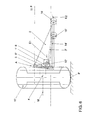
- FIGS. 4 to 6 A second exemplary embodiment will now be explained with reference to FIGS. 4 to 6. This differs from the first exemplary embodiment according to FIGS. 1 to 3 in particular by the arrangement of the tie rod 3 'to the trailing arm 1' and the arrangement of the Hinge axis A 'to the wheel bearing 4, while the basic structure is retained. So for example, the position of the bushings 8 and 10 and the axes E1 and E2 remains in relation on the wheel center axis M unchanged. In the following, therefore, only the Differences described in more detail.
- the trailing arm 1 'of the second embodiment essentially comprises one forwardly extending first section 6 'of a bushing 8 at its front end with an axis E1 for pivotable mounting on a vehicle body, wherein the connection can be made via a rubber bushing.
- the first Trailing arm section 6 ' is flexible in the transverse direction.
- In an area close to the hinge is in the first trailing arm section 6 'a rigid second trailing arm section 7' integrated, which is designed as a receptacle for the tie rod 3 '.
- the bushing 12 ' is partially in a recess in the longitudinal beam 1' added.
- the connection is made in the direction of travel F in front of the wheel center axis M.
- the hinge pillar 5 'lies behind the Wheel bearing 4, the hinge axis A also behind the wheel contact point P the Road surface intersects, as can be seen in particular from Figure 5.
- the wishbone 2 is in turn coupled to the hinge pillar 5, while maintaining it the vehicle-side articulation points is a little longer and under a more pointed one Angle to the trailing arm 1 'on the hinge pillar 5'.
- the control arm 2 extends essentially parallel to the tie rod 3 ', which saves space at the acute angle lies between the control arm 2 and the trailing arm 1 '.
- the vehicle-side sockets 10 and 15 'of the control arm 2 and the tie rod 3' are at the same height above the ground and across the direction of travel F on a common line.
- the Vehicle-side support of the front end of the trailing arm 1 is particularly soft be trained, that is softer than, for example, in the Vehicle independent wheel suspension, which is known from EP 0 691 225 A1. So that can a large longitudinal suspension can be allowed without negatively influencing the toe-in.
- the one through the front elastic bearing of the trailing arm 1, for example Longitudinal amplitude caused by braking is determined by the transverse elasticity of the first Trailing arm section 6 or 6 'compensated, which bends accordingly.
- the Tie rod 3 in cooperation with the rigid rear end of the trailing arm 1 ensures thereby for maintaining a predetermined, desired toe-in on the rear wheel 17. Overall, an improvement in the comfort of the wheel suspension can be achieved since the vibrations transmitted to the vehicle body can be more strongly absorbed, without this at the expense of driving stability.
- the vehicle independent wheel suspension In addition to a flat design, the vehicle independent wheel suspension also stands out due to its light weight and ease of manufacture.
Landscapes
- Engineering & Computer Science (AREA)
- Mechanical Engineering (AREA)
- Vehicle Body Suspensions (AREA)
Abstract
Description
- Figur 1
- eine räumliche Ansicht einer Fahrzeugeinzelradaufhängung eines ersten Ausführungsbeispiels nach der Erfindung,
- Figur 2
- eine Seitenansicht des ersten Ausführungsbeispiels in Richtung der Radinnenseite,
- Figur 3
- eine Ansicht von hinten auf die Fahrzeugeinzelradaufhängung nach Figur 1,
- Figur 4
- eine Ansicht von oben auf eine Fahrzeugeinzelradaufhängung eines zweiten Ausführungsbeispiels nach der Erfindung,
- Figur 5
- eine Seitenansicht des zweiten Ausführungsbeispiels in Richtung der Radinnenseite, und in
- Figur 6
- eine Ansicht von hinten auf die Fahrzeugeinzelradaufhängung nach Figur 4.
- 1,1'
- Längslenker
- 2
- Querlenker
- 3, 3'
- Spurstange
- 4
- Radlager
- 5, 5'
- Scharniersäule
- 6, 6'
- erster Längslenkerabschnitt
- 7, 7'
- zweiter Längslenkerabschnitt
- 8
- Buchse des ersten Längslenkerabschnittes
- 9
- Durchgangsöffnung
- 10, 10'
- fahrzeugseitige Buchse des Querlenkers
- 11
- Durchgangsöffnung
- 12, 12'
- längslenkerseitige Buchse der Spurstange
- 13, 13'
- Durchgangsöffnung
- 14. 14'
- Verbindungsabschnitt
- 15, 15'
- fahrzeugseitige Buchse der Spurstange
- 16
- Durchgangsöffnung
- 17
- Hinterrad
- A, A'
- Scharnierachse, Verbindungslinie zwischen Querlenker und Scharniersäule
- E1
- Schwenkachse der Längslenker-Buchse 8
- E2
- Schwenkachse der Querlenker-Buchse 10
- K, K'
- Schwenkachse der fahrzeugseitigen Buchse der Spurstange
- D, D'
- Schwenkachse der längslenkerseitigen Buchse der Spurstange
- M
- Radmittelachse
- P
- Radaufstandspunkt
Claims (10)
- Fahrzeugeinzelradaufhängung, umfassend einen Längslenker (1, 1') mit einem Radlager (4), der mit einem ersten, vorderen Ende über ein elastisches Lager schwenkbar an einem Fahrzeugaufbau abgestützt ist, und einen Querlenker (2), der in überwiegend vertikaler Ausrichtung zur Abstützung eines Sturzmomentes an zumindest zwei voneinander beabstandeten Punkten entlang einer Achse (A, A') mit dem Längslenker (1, 1') verbunden ist, dadurch gekennzeichnet, daß der Längslenker (1, 1') in Querrichtung biegeweich, in Vertikalrichtung hingegen biegesteif ausgebildet ist, und weiterhin mit einer Spurstange (3, 3') gelenkig gekoppelt ist, die ihrerseits mit einem anderen Ende an dem Fahrzeugaufbau abgestützt ist.
- Fahrzeugeinzelradaufhängung nach Anspruch 1, dadurch gekennzeichnet, daß der Querlenker (2) scharnierartig an dem Längslenker (1, 1') befestigt ist.
- Fahrzeugeinzelradaufhängung nach Anspruch 1 oder 2, dadurch gekennzeichnet, daß der Querlenker (2) fest mit dem Längslenker (1, 1') verbunden ist.
- Fahrzeugeinzelradaufhängung nach einem der Ansprüche 1 bis 3, dadurch gekennzeichnet, daß der Längslenker (1) eine sich im wesentlichen vertikal erstreckende Scharniersäule (5, 5') aufweist, von der sich ein erster Längslenkerabschnitt (6, 6') in Fahrtrichtung (F) nach vorne und ein zweiter Längslenkerabschnitt (7, 7') zu der Spurstange (3, 3') erstreckt, wobei der erste Längslenkerabschnitt (6, 6') in Querrichtung biegeweich und in Vertikalrichtung biegesteif ausgebildet ist.
- Fahrzeugeinzelradaufhängung nach Anspruch 4, dadurch gekennzeichnet, daß beide Längslenkerabschnitte (6, 6', 7, 7') als dreieckförmige Flügel ausgebildet sind, die mit einer Längsseite in im wesentlichen vertikaler Ausrichtung mit der Scharniersäule (5, 5') verbunden sind, wobei der erste Längslenkerabschnitt (6, 6') mit seinem spitzen Ende fahrzeugseitig abgestützt ist und der zweite Längslenkerabschnitt (7, 7') an einem Ende der Spurstange (3, 3') schwenkbar gelagert ist.
- Fahrzeugeinzelradaufhängung nach Anspruch 4 oder 5, dadurch gekennzeichnet, daß der Querlenker (2) als dreieckförmiger Flügel mit gleichbleibender Wanddicke ausgebildet ist, der an einer Längsseite mit der Scharniersäule (5, 5') verbunden ist und an seinem spitzen Ende fahrzeugseitig abgestützt ist.
- Fahrzeugeinzelradaufhängung nach einem der Ansprüche 4 bis 6, dadurch gekennzeichnet, daß die Wanddicke des sowohl in Querrichtung als auch in Vertikalrichtung biegesteifen Querlenkers (2) ein Mehrfaches der Wanddicke des ersten Längslenkerabschnittes (6, 6') beträgt.
- Fahrzeugeinzelradaufhängung nach einem der Ansprüche 4 bis 7, dadurch gekennzeichnet, daß der zweite Längslenkerabschnitt (7, 7') in Fahrtrichtung kürzer ist, als der erste Längslenkerabschnitt (6, 6').
- Fahrzeugeinzelradaufhängung nach einem der Ansprüche 4 bis 8, dadurch gekennzeichnet, daß das Radlager (4) in bezug auf die Fahrtrichtung (F) zwischen der Scharniersäule (5, 5') und der radseitigen Spurstangenanbindung angeordnet ist.
- Fahrzeugeinzelradaufhängung nach einem der Ansprüche 1 bis 9, dadurch gekennzeichnet, daß die Schwenkachse (D, D') des Spurstangenlagers des Längslenkers (1, 1') im wesentlichen horizontal und in Fahrtrichtung (F) orientiert ist.
Applications Claiming Priority (2)
| Application Number | Priority Date | Filing Date | Title |
|---|---|---|---|
| DE10001985 | 2000-01-19 | ||
| DE10001985A DE10001985B4 (de) | 2000-01-19 | 2000-01-19 | Fahrzeugeinzelradaufhängung |
Publications (2)
| Publication Number | Publication Date |
|---|---|
| EP1118478A2 true EP1118478A2 (de) | 2001-07-25 |
| EP1118478A3 EP1118478A3 (de) | 2004-02-04 |
Family
ID=7627923
Family Applications (1)
| Application Number | Title | Priority Date | Filing Date |
|---|---|---|---|
| EP00126563A Withdrawn EP1118478A3 (de) | 2000-01-19 | 2000-12-12 | Fahrzeugeinzelradaufhängung |
Country Status (2)
| Country | Link |
|---|---|
| EP (1) | EP1118478A3 (de) |
| DE (1) | DE10001985B4 (de) |
Cited By (1)
| Publication number | Priority date | Publication date | Assignee | Title |
|---|---|---|---|---|
| WO2017129427A1 (de) * | 2016-01-28 | 2017-08-03 | Volkswagen Aktiengesellschaft | Radaufhängungsvorrichtung |
Families Citing this family (4)
| Publication number | Priority date | Publication date | Assignee | Title |
|---|---|---|---|---|
| DE102005011829A1 (de) * | 2005-03-15 | 2006-09-21 | Volkswagen Ag | Querlenker in Blechkonstruktion |
| DE102008043330A1 (de) * | 2008-10-30 | 2010-05-12 | Zf Friedrichshafen Ag | Radaufhängung für ein Fahrzeug |
| DE102010029032A1 (de) * | 2010-05-17 | 2011-11-17 | Bayerische Motoren Werke Aktiengesellschaft | Hinterradaufhängung eines zweispurigen Fahrzeugs |
| DE102011110981B4 (de) * | 2011-08-18 | 2022-10-06 | Audi Ag | Radaufhängung für die hinteren Räder von Kraftfahrzeugen |
Citations (3)
| Publication number | Priority date | Publication date | Assignee | Title |
|---|---|---|---|---|
| DE1430793A1 (de) | 1962-12-01 | 1969-09-04 | Daimler Benz Ag | Fuehrungslenker fuer Raeder,insbesondere von Kraftfahrzeugen |
| DE3634090A1 (de) | 1986-10-07 | 1988-04-14 | Bayerische Motoren Werke Ag | Hinterachse fuer kraftfahrzeuge |
| EP0691225A1 (de) | 1994-07-07 | 1996-01-10 | Volkswagen Aktiengesellschaft | Einzelradaufhängung für eine Kfz-Rad, insbesondere für ein Hinterrad |
Family Cites Families (5)
| Publication number | Priority date | Publication date | Assignee | Title |
|---|---|---|---|---|
| DE3068376D1 (en) * | 1980-11-14 | 1984-08-02 | Bayerische Motoren Werke Ag | Independent suspension for non-steered wheels of motor vehicles exhibiting a camber variation during suspension movement, especially for passenger vehicles |
| DE3703198C1 (de) * | 1987-02-03 | 1988-05-11 | Bayerische Motoren Werke Ag | Radaufhaengung fuer lenkbare Hinterraeder von mit Vorderradlenkung ausgestatteten Kraftfahrzeugen,insbesondere Personenkraftwagen |
| JPH0238107A (ja) * | 1988-07-29 | 1990-02-07 | Mazda Motor Corp | 車両のサスペンシヨン装置 |
| JPH0274408A (ja) * | 1988-09-09 | 1990-03-14 | Mazda Motor Corp | 車両のサスペンション装置 |
| JPH0285003A (ja) * | 1988-09-21 | 1990-03-26 | Toyota Motor Corp | 車両の独立懸架装置 |
-
2000
- 2000-01-19 DE DE10001985A patent/DE10001985B4/de not_active Expired - Fee Related
- 2000-12-12 EP EP00126563A patent/EP1118478A3/de not_active Withdrawn
Patent Citations (3)
| Publication number | Priority date | Publication date | Assignee | Title |
|---|---|---|---|---|
| DE1430793A1 (de) | 1962-12-01 | 1969-09-04 | Daimler Benz Ag | Fuehrungslenker fuer Raeder,insbesondere von Kraftfahrzeugen |
| DE3634090A1 (de) | 1986-10-07 | 1988-04-14 | Bayerische Motoren Werke Ag | Hinterachse fuer kraftfahrzeuge |
| EP0691225A1 (de) | 1994-07-07 | 1996-01-10 | Volkswagen Aktiengesellschaft | Einzelradaufhängung für eine Kfz-Rad, insbesondere für ein Hinterrad |
Cited By (1)
| Publication number | Priority date | Publication date | Assignee | Title |
|---|---|---|---|---|
| WO2017129427A1 (de) * | 2016-01-28 | 2017-08-03 | Volkswagen Aktiengesellschaft | Radaufhängungsvorrichtung |
Also Published As
| Publication number | Publication date |
|---|---|
| DE10001985B4 (de) | 2009-04-09 |
| DE10001985A1 (de) | 2001-07-26 |
| EP1118478A3 (de) | 2004-02-04 |
Similar Documents
| Publication | Publication Date | Title |
|---|---|---|
| EP0193090B1 (de) | Hinterradaufhängung für Kraftfahrzeuge | |
| DE3331247C2 (de) | Unabhängige Radaufhängung für Kraftfahrzeuge | |
| DE3486249T2 (de) | Hinterradaufhängungssystem für Fahrzeuge. | |
| EP2365912B1 (de) | Schräglenker-achse für ein kraftfahrzeug | |
| DE10133424A1 (de) | Hinterachse eines Personenkraftwagens mit fünf einzelnen Lenkern | |
| EP0656270A1 (de) | Radaufhängung | |
| DE2918605A1 (de) | Einzelradaufhaengung mittels uebereinander angeordneter fuehrungslenker | |
| DE19722650A1 (de) | Hinteres Federungssystem eines Kraftfahrzeugs, welches Fahrbahnunregelmäßigkeiten und Radbremsung unterscheiden kann | |
| EP3452310B1 (de) | Einzelradaufhängung eines fahrzeugs mit einem radführenden blattfederelement aus einem faserverbund-werkstoff | |
| DE4207315A1 (de) | Einzelradaufhaengungsvorrichtung fuer ein fahrzeug | |
| EP2435263B1 (de) | Fahrzeug-einzelradaufhängung | |
| DE68903870T2 (de) | Fahrzeugradaufhaengung mit einer kombination eines umgekehrten a-lenkers und eines i-lenkers. | |
| DE102010029032A1 (de) | Hinterradaufhängung eines zweispurigen Fahrzeugs | |
| DE60306730T2 (de) | Lenkeinrichtung für die Trage-Einrichtung der Hinterradnabe in Motorfahrzeugen | |
| EP1419909A2 (de) | Vierlenker-Hinterradachse für ein Kraftfahrzeug | |
| DE102007007439A1 (de) | Achse eines zweispurigen Fahrzeugs mit einem torsionsweichen Verbundlenker | |
| EP1995087A2 (de) | Radaufhängung für Kraftfahrzeuge | |
| DE4136276B4 (de) | Vorderradaufhängung | |
| DE10001985B4 (de) | Fahrzeugeinzelradaufhängung | |
| DE2439365A1 (de) | Radaufhaengung fuer kraftfahrzeuge, insbesondere personenkraftwagen | |
| EP1277603B1 (de) | Mehrlenker-Einzelradaufhängung, insbesondere Aufhängung eines lenkbaren Vorderrads eines Kraftfahrzeugs | |
| DE102020003902A1 (de) | Radaufhängung für ein Fahrzeug, insbesondere für einen Kraftwagen | |
| DE19535923B4 (de) | Unabhängige Radaufhängung für angetriebene Hinterräder von Kraftfahrzeugen | |
| DE3913238A1 (de) | Radaufhaengung fuer kraftfahrzeuge | |
| DE19746931C1 (de) | Fahrzeugachsaufhängung mit Lenkern |
Legal Events
| Date | Code | Title | Description |
|---|---|---|---|
| PUAI | Public reference made under article 153(3) epc to a published international application that has entered the european phase |
Free format text: ORIGINAL CODE: 0009012 |
|
| AK | Designated contracting states |
Kind code of ref document: A2 Designated state(s): AT BE CH CY DE DK ES FI FR GB GR IE IT LI LU MC NL PT SE TR |
|
| AX | Request for extension of the european patent |
Free format text: AL;LT;LV;MK;RO;SI |
|
| PUAL | Search report despatched |
Free format text: ORIGINAL CODE: 0009013 |
|
| AK | Designated contracting states |
Kind code of ref document: A3 Designated state(s): AT BE CH CY DE DK ES FI FR GB GR IE IT LI LU MC NL PT SE TR |
|
| AX | Request for extension of the european patent |
Extension state: AL LT LV MK RO SI |
|
| RIC1 | Information provided on ipc code assigned before grant |
Ipc: 7B 60G 3/22 B Ipc: 7B 60G 3/26 B Ipc: 7B 60G 3/18 B Ipc: 7B 60G 3/20 A |
|
| 17P | Request for examination filed |
Effective date: 20040804 |
|
| AKX | Designation fees paid |
Designated state(s): AT BE CH CY DE DK ES FI FR GB GR IE IT LI LU MC NL PT SE TR |
|
| GRAP | Despatch of communication of intention to grant a patent |
Free format text: ORIGINAL CODE: EPIDOSNIGR1 |
|
| STAA | Information on the status of an ep patent application or granted ep patent |
Free format text: STATUS: THE APPLICATION IS DEEMED TO BE WITHDRAWN |
|
| 18D | Application deemed to be withdrawn |
Effective date: 20051201 |