EP1118442A2 - Mold for producing fuel cell separator - Google Patents
Mold for producing fuel cell separator Download PDFInfo
- Publication number
- EP1118442A2 EP1118442A2 EP00127295A EP00127295A EP1118442A2 EP 1118442 A2 EP1118442 A2 EP 1118442A2 EP 00127295 A EP00127295 A EP 00127295A EP 00127295 A EP00127295 A EP 00127295A EP 1118442 A2 EP1118442 A2 EP 1118442A2
- Authority
- EP
- European Patent Office
- Prior art keywords
- mold
- fuel cell
- cavity
- separator
- cell separator
- Prior art date
- Legal status (The legal status is an assumption and is not a legal conclusion. Google has not performed a legal analysis and makes no representation as to the accuracy of the status listed.)
- Withdrawn
Links
Images



Classifications
-
- B—PERFORMING OPERATIONS; TRANSPORTING
- B29—WORKING OF PLASTICS; WORKING OF SUBSTANCES IN A PLASTIC STATE IN GENERAL
- B29C—SHAPING OR JOINING OF PLASTICS; SHAPING OF MATERIAL IN A PLASTIC STATE, NOT OTHERWISE PROVIDED FOR; AFTER-TREATMENT OF THE SHAPED PRODUCTS, e.g. REPAIRING
- B29C33/00—Moulds or cores; Details thereof or accessories therefor
- B29C33/0055—Moulds or cores; Details thereof or accessories therefor with incorporated overflow cavities
-
- B—PERFORMING OPERATIONS; TRANSPORTING
- B29—WORKING OF PLASTICS; WORKING OF SUBSTANCES IN A PLASTIC STATE IN GENERAL
- B29C—SHAPING OR JOINING OF PLASTICS; SHAPING OF MATERIAL IN A PLASTIC STATE, NOT OTHERWISE PROVIDED FOR; AFTER-TREATMENT OF THE SHAPED PRODUCTS, e.g. REPAIRING
- B29C43/00—Compression moulding, i.e. applying external pressure to flow the moulding material; Apparatus therefor
- B29C43/003—Compression moulding, i.e. applying external pressure to flow the moulding material; Apparatus therefor characterised by the choice of material
-
- B—PERFORMING OPERATIONS; TRANSPORTING
- B29—WORKING OF PLASTICS; WORKING OF SUBSTANCES IN A PLASTIC STATE IN GENERAL
- B29C—SHAPING OR JOINING OF PLASTICS; SHAPING OF MATERIAL IN A PLASTIC STATE, NOT OTHERWISE PROVIDED FOR; AFTER-TREATMENT OF THE SHAPED PRODUCTS, e.g. REPAIRING
- B29C43/00—Compression moulding, i.e. applying external pressure to flow the moulding material; Apparatus therefor
- B29C43/006—Pressing and sintering powders, granules or fibres
-
- B—PERFORMING OPERATIONS; TRANSPORTING
- B29—WORKING OF PLASTICS; WORKING OF SUBSTANCES IN A PLASTIC STATE IN GENERAL
- B29K—INDEXING SCHEME ASSOCIATED WITH SUBCLASSES B29B, B29C OR B29D, RELATING TO MOULDING MATERIALS OR TO MATERIALS FOR MOULDS, REINFORCEMENTS, FILLERS OR PREFORMED PARTS, e.g. INSERTS
- B29K2503/00—Use of resin-bonded materials as filler
- B29K2503/04—Inorganic materials
-
- Y—GENERAL TAGGING OF NEW TECHNOLOGICAL DEVELOPMENTS; GENERAL TAGGING OF CROSS-SECTIONAL TECHNOLOGIES SPANNING OVER SEVERAL SECTIONS OF THE IPC; TECHNICAL SUBJECTS COVERED BY FORMER USPC CROSS-REFERENCE ART COLLECTIONS [XRACs] AND DIGESTS
- Y10—TECHNICAL SUBJECTS COVERED BY FORMER USPC
- Y10S—TECHNICAL SUBJECTS COVERED BY FORMER USPC CROSS-REFERENCE ART COLLECTIONS [XRACs] AND DIGESTS
- Y10S425/00—Plastic article or earthenware shaping or treating: apparatus
- Y10S425/047—Seal ring
Definitions
- the present invention relates to a production of a fuel cell separator, and more particularly to a mold capable of achieving a high dimensional accuracy in the molding process.
- Fuel cells of the type where a fuel gas and an oxidant gas are used paticularly, solid polymer type fuel cells have a structure in which an ion coductive solid electrolyte membrane is sandwiched between an anode and a cathode which are gas diffusion electrodes carrying a catalyst thereon, the sandwich being further sandwiched between separators.
- the separator on the anode side supplies hydrogen gas as the fuel gas to the anode
- the separtor on the cathode side supplies oxygen gas as the oxidant gas to the cathode.
- FIG 4 is a diagram illustrating such a fuel cell separator.
- a separator 1 has a planar surface with a narrow channel la prvided thereon.
- the channel la is meandering with a small pitch on the whole surface of the separator substantially across the entire surface of the separator.
- the channel 1a may be provided either on both sides of the separator, as illustrated in Figure 4b, or on only one side thereof.
- Such a separator 1 requires a high accuracy in it's thickness. This is because the separator contacts with the anode or cathode and electricity is conducted therebetween, so that if the surface accuracy is poor, the contact area therebetween decreases, thereby lowering the conductivity. Moreover, if the surface accuracy is rough, a gap may occur between the separator and the anode or cathode so that a force is imparted in such a direction as to squash the gap, thereby cracking the separator. In other words, as the surface accuracy increases, the contact resistance decreases and the separator is less likely to crack, thus improving the performance of the fuel cell.
- a conventional way of producing a fuel cell separator is as follows. First, as the starting material, a material compound is produced by, for example, mixing 25 parts by weight of a phenol resin to 100 parts by weight of a flake graphite (average particle diameter: 30 ⁇ m), and the material compound is processed into a powder form. It is sometimes processed into a granular form or a pellet form, as well as a powder form.
- the mold consists of a lower mold 2, a middle mold 3 and an upper mold 4.
- a cavity 5 for forming the fuel cell separator 1 therein is defined among the three molds. Specifically, the channel la for the reverse surface of the fuel cell separator 1 is provided on the lower mold 4; the middle mold 3 has an aperture which corresponds to the outer shape of the fuel cell separator 1; the channel la for the front surface of the fuel cell separator 1 is provided on the upper mold 2; and the distance between the upper and lower molds corresponds to the thickness of the separator.
- the lower mold 4 and the middle mold 3 are attached to the fixed bed side of a press machine, and the upper mold is attached to the upper side of the press machine which can be raised and lowered.
- the upper mold 2 is retracted by being raised up, and then the above-described powder form material is charged into the middle mold 3.
- the charging amount is adjusted to a weight which is slightly in excess of the weight of the produced fuel cell separator. This is to ensure that the material is sufficiently charged into every corner of the cavity 5.
- the upper mold 2 is lowered to compress the powder form material, and the mold is heated by a heater (not shown) to about 432 K.
- the separator material is melted by the heat application, and is advanced into every corner of the cavity 5 by the applied pressure (about 2 KPa).
- Some gas vent holes 7 for communicating the cavity 5 to the outside is provided at appropriate locations of the mold to externally discharge the air which is originally contained in the cavity 5 and a gas which is generated from the material, thereby ensuring that no void is produced in the fuel cell separator.
- a vacuum pump may be used for the gas ventilation.
- a mold as described above has the following problem. Since an amount of material that is slightly in excess of the amount sufficient to fill up the cavity is charged into the mold, there is some material which cannot be accommodated within the cavity 5 when the material is melted by the pressure and heat application. This excess of material moves up along the gap between the middle mold 3 and the lower mold 4 and then into the gap between the upper surface of the middle mold and the lower surface of the upper mold, where it is cooled and cured. This run-out portion is commonly called “flash" 6.
- the flash 6 is formed with a uniform thickness between the middle mold 3 and the upper mold 2.
- the flash 6 has an uneven distribution, e.g., it occurs in a single location as illustrated in the figure.
- the upper mold 2 is slanted as illustrated in Figure 5b, thereby causing a 0.2 mm or greater difference or unevenness in the thickness of the produced fuel cell separator 1.
- the present invention has been made in view of the above-described circumstances, and has an object of providing a mold for a fuel cell separator with which a flash, even if it occurs, does not cause a thickness unevenness.
- the present invention provides a mold for producing a fuel cell separator, comprising a plurality of molds, a fuel cell molding cavity for separator being defined among the molds, wherein at least one of the molds is provided with a flash reservoir cavity which is communicated with the cavity.
- the flash reservoir cavity may be provided by digging on a surface of one mold along which the mold contacts with another mold, so that the flash reservoir cavity extends to surround the fuel cell molding cavity for separator; the surface on which the flash cavity is provided by digging may closely contact the other mold, thereby defining the fuel cell molding cavity for separator; a sealing member may be provided external to the flash reservoir cavity for providing sealing; and the mold may be for use with a press machine.
- Figure 1 is a diagram illustrating a mold for producing a fuel cell separator according to the present invention, wherein Figure la is a cross-sectional view, and Figure 1b is a top view illustrating a middle mold.
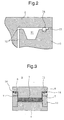
- Figure 2 is an enlarged view illustrating a portion where the middle mold and the upper mold shown in Figure 1 contact with each other.
- the mold of the present invention has a flash reservoir cavity 11 provided on a surface of a middle mold 10 along which the middle mold contacts with the upper mold 2, and has a passage 12 defined between the middle mold 10 and the upper mold 2 for communicating the cavity 5, which is defined among the plurality of molds, and the cavity 11 with each other. While the passage 12 may be provided only in one location, it may be provided in a plurality of locations, in which case the melted material moves smoothly. Alternatively, a gap between molds can be utilized as the communication passage 12.
- the flash reservoir cavity 11 may be provided only on one side of the cavity 5, it may be provided around the entire periphery of the cavity 5 as in the illustrated example, in which case it is possible to effectively increase the volume of the flash reservoir cavity 11 without increasing the size of the mold.
- a sealing groove 13 is further provided external to the flash reservoir cavity 11 into which a sealing member 14 such as a rubber-made O-ring, or the like, is inserted so as to prevent the melted material from running out to the outside.
- a sealing member 14 such as a rubber-made O-ring, or the like
- Figure 3 illustrates a fuel cell separator having been formed in the mold of Figure 1.
- a powder form material as that of the conventional example, is charged after the upper mold 2 has been raised.
- the charging amount is adjusted to an amount which is in excess of the volume of the fuel cell separator but no greater than the sum of the volume of the fuel cell separator and the volume of the flash reservoir cavity 11.
- the upper mold 2 is lowered, and the material is melted by compression and heating under conditions similar to those of the conventional example, so that the material is charged into every corner of the cavity 5.
- a portion of the charged material in excess of the volume of the fuel cell separator 1 passes through the passage 12 into the flash reservoir cavity 11, where it is cured into a flash 8.
- the excess of material is not so much as to fill up the entire flash reservoir cavity 11, there may be a case where the material flow is localized to one location along the flash reservoir cavity 11. In such a case, the material in that location may overflow to the outside of the cavity 11 and become cured between the upper mold 2 and the middle mold 10, thereby pushing up the upper mold 2.
- the sealing groove 13 is provided by digging external to the flash reservoir cavity 11 with the sealing member 14 being placed therein so as to prevent the material from running out to the outside. In this way, it is possible to ensure the close contact of the upper mold 2 with the middle mold 10, and to maintain the thickness dimension of the fuel cell separator 1 with a good accuracy.
- the mold of the present invention is designed so that the surface of a mold on which the flash reservoir cavity is provided and the surface of another mold facing the mold directly and closely contact with each other.
- the mold is divided into three pieces, i.e., the upper mold, the middle mold and the lower mold. Alternatively, it may be divided into two pieces, i.e., an upper mold and a lower mold, or more than three molds may be used. Furthermore, while the example described above is of the type for use with a press machine, the structure of the present invention is also applicable to a mold for use with injection molding.
- the present invention provides a mold for producing a fuel cell separator, comprising a plurality of molds and a fuel cell molding cavity for separator being defined among the molds, wherein at least one of the molds is provided with a flash reservoir cavity which is communicated with the cavity.
- a mold for producing a fuel cell separator comprising a plurality of molds and a fuel cell molding cavity for separator being defined among the molds, wherein at least one of the molds is provided with a flash reservoir cavity which is communicated with the cavity.
- the flash reservoir cavity is provided by digging on a surface of one mold along which the mold contacts with another mold, so that the flash reservoir cavity extends to surround the fuel cell molding cavity for separator, it is possible to provide a flash reservoir cavity which is large in volume without increasing the size of the mold.
Landscapes
- Engineering & Computer Science (AREA)
- Mechanical Engineering (AREA)
- Fuel Cell (AREA)
- Moulds For Moulding Plastics Or The Like (AREA)
- Casting Or Compression Moulding Of Plastics Or The Like (AREA)
Abstract
Description
Fuel cells of the type where a fuel gas and an oxidant gas are used, paticularly, solid polymer type fuel cells have a structure in which an ion coductive solid electrolyte membrane is sandwiched between an anode and a cathode which are gas diffusion electrodes carrying a catalyst thereon, the sandwich being further sandwiched between separators. The separator on the anode side supplies hydrogen gas as the fuel gas to the anode, and the separtor on the cathode side supplies oxygen gas as the oxidant gas to the cathode.
Claims (5)
- A mold for producing a fuel cell separator, comprising a plurality of molds and a fuel cell molding cavity for separator being defined among the molds, wherein at least one of the molds is provided with a flash reservoir cavity which is communicated with the cavity.
- A mold for producing a fuel cell separator according to claim 1, wherein the flash reservoir cavity is provided by digging on a surface of one mold along which the mold contacts with another mold, so that the flash reservoir cavity extends to surround the fuel cell molding cavity for separator.
- A mold for producing a fuel cell separator according to claim 2, wherein the surface on which the flash cavity is provided by digging closely contacts the other mold, thereby defining the fuel cell molding cavity for separator.
- A mold for producing a fuel cell separator according to claim 2, wherein a sealing member is provided external to the flash reservoir cavity for providing sealing.
- A mold for producing a fuel cell separator according to claim 1, wherein the mold is for use with a press machine.
Applications Claiming Priority (2)
| Application Number | Priority Date | Filing Date | Title |
|---|---|---|---|
| JP2000011095 | 2000-01-20 | ||
| JP2000011095A JP2001198921A (en) | 2000-01-20 | 2000-01-20 | Mold for fuel cell separator production |
Publications (2)
| Publication Number | Publication Date |
|---|---|
| EP1118442A2 true EP1118442A2 (en) | 2001-07-25 |
| EP1118442A3 EP1118442A3 (en) | 2003-01-02 |
Family
ID=18539007
Family Applications (1)
| Application Number | Title | Priority Date | Filing Date |
|---|---|---|---|
| EP00127295A Withdrawn EP1118442A3 (en) | 2000-01-20 | 2000-12-19 | Mold for producing fuel cell separator |
Country Status (4)
| Country | Link |
|---|---|
| US (1) | US6579083B2 (en) |
| EP (1) | EP1118442A3 (en) |
| JP (1) | JP2001198921A (en) |
| CA (1) | CA2331026A1 (en) |
Cited By (5)
| Publication number | Priority date | Publication date | Assignee | Title |
|---|---|---|---|---|
| EP1317009A3 (en) * | 2001-12-01 | 2003-10-15 | Krauss-Maffei Kunststofftechnik GmbH | Method for manufacturing electrode plates by injection moulding of graphite or the like loaded with plastic |
| CZ302658B6 (en) * | 2010-09-17 | 2011-08-17 | Vysoké ucení technické v Brne | Process for producing insulation boards for insulation block of composite material and press mold for making the same |
| EP2415580A4 (en) * | 2009-03-30 | 2016-07-27 | Showa Denko Kk | A STRAP PRECISION METHOD AND A METHOD FOR PRODUCING A FUEL CELL PARAMETER |
| CN107068946A (en) * | 2017-04-22 | 2017-08-18 | 福建师范大学 | One kind manufacture UHMWPE lithium battery diaphragm die devices |
| CN111070535A (en) * | 2019-12-11 | 2020-04-28 | 青岛海信模具有限公司 | Compression molding die |
Families Citing this family (14)
| Publication number | Priority date | Publication date | Assignee | Title |
|---|---|---|---|---|
| CA2464204C (en) * | 2003-04-14 | 2009-08-11 | Matsushita Electric Industrial Co., Ltd. | Polymer electrolyte fuel cell and conductive separator for the same |
| DE10325097A1 (en) * | 2003-06-03 | 2004-12-23 | Arvinmeritor Gmbh | foaming |
| TWI232156B (en) * | 2003-06-25 | 2005-05-11 | Coretronic Corp | Method for forming microstructure optical elements |
| JP4721649B2 (en) * | 2004-03-23 | 2011-07-13 | 本田技研工業株式会社 | Metal separator for fuel cell and method for manufacturing fuel cell |
| JP2006289774A (en) * | 2005-04-11 | 2006-10-26 | Dainippon Ink & Chem Inc | Multi-cavity compression mold for manufacturing fuel cell separator and method for manufacturing fuel cell separator using the same |
| JP4587177B2 (en) * | 2005-06-28 | 2010-11-24 | 東海カーボン株式会社 | Manufacturing method of fuel cell separator |
| EP2071654B1 (en) | 2006-10-05 | 2013-05-08 | DIC Corporation | Separator for fuel batteries and fuel batteries |
| US8721315B2 (en) * | 2010-09-13 | 2014-05-13 | Amcor Limited | Method of handling liquid to prevent machine contamination during filling |
| JP5877652B2 (en) * | 2011-05-11 | 2016-03-08 | 住友ゴム工業株式会社 | Tire vulcanization mold |
| US9096028B2 (en) * | 2011-08-10 | 2015-08-04 | Nike, Inc. | Article of footwear formed from two preforms and method and mold for manufacturing same |
| US9731464B2 (en) | 2011-08-10 | 2017-08-15 | Nike, Inc. | Article of footwear formed from two preforms and method and mold for manufacturing same |
| TWI817060B (en) * | 2020-05-08 | 2023-10-01 | 鉅鋼機械股份有限公司 | Improved structure of gas counter-pressure molding mold |
| TWI772153B (en) * | 2021-08-18 | 2022-07-21 | 臺灣塑膠工業股份有限公司 | Mold for carbon fiber composite material |
| EP4463299A1 (en) * | 2022-01-14 | 2024-11-20 | Invibio Device Component Manufacturing Limited | A mould tool |
Family Cites Families (13)
| Publication number | Priority date | Publication date | Assignee | Title |
|---|---|---|---|---|
| US2733494A (en) * | 1956-02-07 | there | ||
| US2731669A (en) * | 1950-03-02 | 1956-01-24 | Dayton Rubber Company | Sponge rubber mold |
| US2633603A (en) * | 1950-06-28 | 1953-04-07 | Hiram N Huse | Mold |
| GB791552A (en) * | 1954-11-10 | 1958-03-05 | Norman Whitaker Wright | Improvements in or relating to the moulding of fibrous material |
| US3287486A (en) * | 1963-04-15 | 1966-11-22 | Us Rubber Co | Molding apparatus and method employing thermal expansion and contraction |
| CH567927A5 (en) * | 1974-08-21 | 1975-10-15 | Schiesser Ag | |
| DE3405032C1 (en) * | 1984-02-13 | 1985-04-04 | Licentia Patent-Verwaltungs-Gmbh, 6000 Frankfurt | Device for producing pressed parts from thermosets |
| US5023041A (en) * | 1987-12-10 | 1991-06-11 | General Electric Company | Method for making a fiber reinforced composite article |
| JP2593772B2 (en) * | 1992-09-01 | 1997-03-26 | 川崎重工業株式会社 | Manufacturing method for composite products |
| JPH08180892A (en) * | 1994-12-26 | 1996-07-12 | Toyota Motor Corp | Method for manufacturing current collector for fuel cell |
| JPH1040937A (en) * | 1996-07-18 | 1998-02-13 | Toyota Motor Corp | Method and apparatus for manufacturing current collector for fuel cell |
| JP4000651B2 (en) * | 1998-01-19 | 2007-10-31 | トヨタ自動車株式会社 | Manufacturing method of fuel cell separator |
| US6180275B1 (en) * | 1998-11-18 | 2001-01-30 | Energy Partners, L.C. | Fuel cell collector plate and method of fabrication |
-
2000
- 2000-01-20 JP JP2000011095A patent/JP2001198921A/en active Pending
- 2000-12-19 EP EP00127295A patent/EP1118442A3/en not_active Withdrawn
-
2001
- 2001-01-10 CA CA002331026A patent/CA2331026A1/en not_active Abandoned
- 2001-01-12 US US09/760,164 patent/US6579083B2/en not_active Expired - Fee Related
Cited By (8)
| Publication number | Priority date | Publication date | Assignee | Title |
|---|---|---|---|---|
| EP1317009A3 (en) * | 2001-12-01 | 2003-10-15 | Krauss-Maffei Kunststofftechnik GmbH | Method for manufacturing electrode plates by injection moulding of graphite or the like loaded with plastic |
| EP2415580A4 (en) * | 2009-03-30 | 2016-07-27 | Showa Denko Kk | A STRAP PRECISION METHOD AND A METHOD FOR PRODUCING A FUEL CELL PARAMETER |
| US9789634B2 (en) | 2009-03-30 | 2017-10-17 | Showa Denko K.K. | Sheet press molding method and method of manufacturing fuel cell separator |
| CZ302658B6 (en) * | 2010-09-17 | 2011-08-17 | Vysoké ucení technické v Brne | Process for producing insulation boards for insulation block of composite material and press mold for making the same |
| CN107068946A (en) * | 2017-04-22 | 2017-08-18 | 福建师范大学 | One kind manufacture UHMWPE lithium battery diaphragm die devices |
| CN107068946B (en) * | 2017-04-22 | 2019-12-13 | 福建师范大学 | A device for manufacturing UHMWPE lithium battery diaphragm mold |
| CN111070535A (en) * | 2019-12-11 | 2020-04-28 | 青岛海信模具有限公司 | Compression molding die |
| CN111070535B (en) * | 2019-12-11 | 2021-11-05 | 青岛海信模具有限公司 | Compression molding die |
Also Published As
| Publication number | Publication date |
|---|---|
| CA2331026A1 (en) | 2001-07-20 |
| EP1118442A3 (en) | 2003-01-02 |
| US20020004082A1 (en) | 2002-01-10 |
| US6579083B2 (en) | 2003-06-17 |
| JP2001198921A (en) | 2001-07-24 |
Similar Documents
| Publication | Publication Date | Title |
|---|---|---|
| US6579083B2 (en) | Mold for producing fuel cell separator | |
| EP2058883B1 (en) | Polymer electrolyte fuel cell and electrode/film/frame assembly manufacturing method | |
| US6827747B2 (en) | PEM fuel cell separator plate | |
| EP2445046B1 (en) | Fuel cell sealing structure | |
| KR100443106B1 (en) | Polymer electrolyte type fuel cell and production method therefor | |
| CA2323167C (en) | Separator for a fuel cell | |
| US20020182473A1 (en) | Fuel cell separator plate having controlled fiber orientation and method of manufacture | |
| US6617068B2 (en) | Bi-zone water transport plate for a fuel cell | |
| EP1378953B1 (en) | Polymer electrolyte fuel cell and production method of separator plate thereof | |
| EP2475036A1 (en) | Membrane electrode assembly, production method for same, and fuel cell | |
| US4165349A (en) | Method for fabricating a ribbed electrode substrate | |
| US20030027030A1 (en) | Fuel-cell separator, production of the same, and fuel cell | |
| EP1168473B1 (en) | Separator for a fuel cell battery and method of producing the same | |
| US6517338B1 (en) | Set of molding dies for fuel-cell separator | |
| US20190393529A1 (en) | Unit cell of fuel cell and method of manufacturing the same | |
| US20070134541A1 (en) | Fuel cell | |
| US7220512B2 (en) | Separator plate for polymer electrolyte fuel cell and polymer electrolyte fuel cell using the same | |
| KR20020094908A (en) | Method for producing fuel cell, and fuel cell | |
| US6815111B1 (en) | Separator for a fuel cell and a method of producing the same | |
| US7033692B1 (en) | Fuel cell separator | |
| KR101762375B1 (en) | Gasket for fuel cell | |
| JP2002373670A (en) | Manufacturing method of fuel cell separator | |
| KR101193131B1 (en) | Mold structure for manufacturing fuelcell separator | |
| JP2006173077A (en) | Separator manufacturing method | |
| JP2005243415A (en) | Method for manufacturing fuel cell separator and fuel cell separator |
Legal Events
| Date | Code | Title | Description |
|---|---|---|---|
| PUAI | Public reference made under article 153(3) epc to a published international application that has entered the european phase |
Free format text: ORIGINAL CODE: 0009012 |
|
| AK | Designated contracting states |
Kind code of ref document: A2 Designated state(s): AT BE CH CY DE DK ES FI FR GB GR IE IT LI LU MC NL PT SE TR |
|
| AX | Request for extension of the european patent |
Free format text: AL;LT;LV;MK;RO;SI |
|
| PUAL | Search report despatched |
Free format text: ORIGINAL CODE: 0009013 |
|
| AK | Designated contracting states |
Kind code of ref document: A3 Designated state(s): AT BE CH CY DE DK ES FI FR GB GR IE IT LI LU MC NL PT SE TR |
|
| AX | Request for extension of the european patent |
Free format text: AL;LT;LV;MK;RO;SI |
|
| RIC1 | Information provided on ipc code assigned before grant |
Free format text: 7B 29C 33/00 A, 7B 29C 45/26 B, 7B 29C 43/36 B |
|
| 17P | Request for examination filed |
Effective date: 20030506 |
|
| 17Q | First examination report despatched |
Effective date: 20030528 |
|
| AKX | Designation fees paid |
Designated state(s): DE FR GB |
|
| STAA | Information on the status of an ep patent application or granted ep patent |
Free format text: STATUS: THE APPLICATION IS DEEMED TO BE WITHDRAWN |
|
| 18D | Application deemed to be withdrawn |
Effective date: 20040701 |