EP1118399A1 - Apparatus for measuring the bending angle of a workpiece - Google Patents
Apparatus for measuring the bending angle of a workpiece Download PDFInfo
- Publication number
- EP1118399A1 EP1118399A1 EP01200091A EP01200091A EP1118399A1 EP 1118399 A1 EP1118399 A1 EP 1118399A1 EP 01200091 A EP01200091 A EP 01200091A EP 01200091 A EP01200091 A EP 01200091A EP 1118399 A1 EP1118399 A1 EP 1118399A1
- Authority
- EP
- European Patent Office
- Prior art keywords
- bending line
- measuring
- bending
- workpiece
- feeler
- Prior art date
- Legal status (The legal status is an assumption and is not a legal conclusion. Google has not performed a legal analysis and makes no representation as to the accuracy of the status listed.)
- Withdrawn
Links
- 238000005452 bending Methods 0.000 title claims abstract description 103
- 230000001419 dependent effect Effects 0.000 claims abstract description 10
- 230000008878 coupling Effects 0.000 claims description 7
- 238000010168 coupling process Methods 0.000 claims description 7
- 238000005859 coupling reaction Methods 0.000 claims description 7
- 238000010276 construction Methods 0.000 description 2
- 238000005259 measurement Methods 0.000 description 2
- 230000003287 optical effect Effects 0.000 description 2
- 238000004519 manufacturing process Methods 0.000 description 1
- 230000013011 mating Effects 0.000 description 1
Images



Classifications
-
- B—PERFORMING OPERATIONS; TRANSPORTING
- B21—MECHANICAL METAL-WORKING WITHOUT ESSENTIALLY REMOVING MATERIAL; PUNCHING METAL
- B21D—WORKING OR PROCESSING OF SHEET METAL OR METAL TUBES, RODS OR PROFILES WITHOUT ESSENTIALLY REMOVING MATERIAL; PUNCHING METAL
- B21D5/00—Bending sheet metal along straight lines, e.g. to form simple curves
- B21D5/02—Bending sheet metal along straight lines, e.g. to form simple curves on press brakes without making use of clamping means
- B21D5/0209—Tools therefor
Definitions
- the invention relates to apparatus for measuring the bending angle of a workpiece, comprising a housing provided with measuring devices which are disposed on either side of a bending line, which measuring devices are capable of delivering signals dependent on the movement of the workpiece with respect to a datum plane, and a processing unit which is capable of deriving the overall bending angle of the workpiece from said signals, wherein a first and a second measuring device are disposed on a first side of the bending line, the signals from which measuring devices are dependent on two points of the workpiece located at different distances from the bending line, from which the processing unit can derive the sub-angle of bend on the first side of the bending line.
- Such an apparatus is known from GB-A-2 072 551.
- the measuring devices of this prior art apparatus include two feelers, which are arranged one beside another in a direction transversely to the bending line, as a result of which the dimensions of each feeler are only small, on account of the small amount of space that is available.
- the feelers of the prior art apparatus are comparatively vulnerable.
- the angle that is derived from the difference in movement amounts to half the bending angle. This in only correct, however, when the folding line of the workpiece and the bending line of the punch are in line with the direction of the bending operation, which is not the case under all circumstances. With the prior art apparatus this may lead to measuring errors.
- GB-A-2 072 551 also discloses an embodiment wherein a feeler is disposed on either side of the bending line, so that the angle can be measured on both sides of the bending line. The angle is thereby derived from the movement of one feeler, which also leads to a less accurate measurement of the bending angle.
- WO-A-9641690 discloses a measuring apparatus that includes two feelers, which are in contact with the workpiece on either side of the bending line, wherein the possible shifting of the folding line of the workpiece with respect to the bending line of the punch can be derived from a movement of said feelers in a direction transversely to the bending line.
- slots are formed in the housing for the feelers, which slots intersect the bending line, so that said slots need to be narrow. As a result, the feelers are relatively vulnerable.
- the object of the invention is to provide an apparatus of the above kind which has been simplified in comparison with the apparatus disclosed in the aforesaid international patent application, and by means of which it is nevertheless possible to determine the bending angle with great accuracy.
- the apparatus according to the invention is characterized in that a third measuring device is disposed on the second side of the bending line, which measuring device is capable of delivering a signal dependent on the shifting of a point of the workpiece that is located at a specified distance from the bending line, wherein the processing unit is arranged for determining the sub-angle of bend and the overall bending angle on the basis of the signal from said third measuring device and said specified distance.
- the ratio between the sub-angles of bend on either side of the bending line is measured by means of the signal from the third measuring device, by comparing said signal to a signal from a measuring device on the first side of the bending line, as a result of which an apparatus is obtained which is of simpler design and which is capable of determining the overall bending angle with a higher degree of accuracy.
- the apparatus according to the invention has the advantage that only one measuring device is required on one side of the bending line, which measuring device is disposed relatively close to the bending line, as a result of which the dimensions of the freely projecting end of the housing of the apparatus can be reduced.
- the free end of the punch can be designed to have relatively small dimensions. This makes it possible to produce workpieces having edges that have been flanged to a U-shape, whose legs may be spaced a small distance apart.
- Fig. 1 is a perspective, schematic view of part of an apparatus for bending workpieces, which is fitted with an embodiment of the apparatus for measuring the bending angle according to the invention.
- Fig. 2 is a sectional view along plane II-II in Fig. 1.
- Fig. 3 is a sectional view along plane III-III in Fig. 1.
- Fig. 4 is a sectional view along plane IV-IV in Fig. 1.
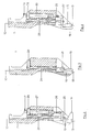
- Fig. 5 is a sectional view corresponding to Fig. 4 of a second embodiment of the apparatus according to the invention, intended for use with a so-called 90° punch.
- Fig. 6 is a sectional view corresponding to Fig. 2 of the apparatus of Fig. 5.
- Fig. 7 shows a part of the apparatus of Fig. 5, wherein a part of a workpiece is schematically indicated.
- Fig. 1 shows in perspective view a part of an apparatus for bending workpieces, in particular for bending plate-shaped workpieces.
- the bending apparatus comprises a die block 2 including a groove 3 of V-shaped section, which die block 2 is supported on a table 4 of the bending apparatus.
- the bending apparatus furthermore comprises a punch 5, which is schematically indicated by dashed lines.
- a measuring apparatus 6 for measuring the bending angle of workpiece 1 is aligned with punch 5.
- the measuring apparatus comprises a housing 7, the shape of at least the end of which corresponds to the shape of the end of punch 5. It is noted that it is not necessary for the shape of housing 7 to correspond to the shape of punch 5.
- Housing 7 may have any desired shape, as long as said shape does not conflict with the shape of the workpiece to be bent. Housing 7 is mounted in an upper beam 8 of the bending apparatus in the same manner as punch 5 by means of a clamp 9. Although the measuring apparatus 6 is mounted on one end of the upper beam in Fig. 1, it is also possible to mount the measuring apparatus 6 in the upper beam at another location, if desired. Furthermore it is possible to mount more than one measuring device in the upper beam.
- the bending apparatus furthermore comprises a driving unit (not shown) for moving die block 2 and punch 3 with respect to each other in a bending direction for carrying out a bending operation on workpiece 1.
- the direction of the bending operation is indicated in a broken line 10 in the drawing.
- the construction of the bending apparatus does not form part of the present invention and consequently it is not described in more detail herein.
- the construction may be of a type which is known per se.
- Housing 7, like punch 5 includes an end having sloping flanks 11, 12, which define a bending line 13 that extends in the longitudinal direction of punch 5 and housing 7. Sloping flanks 11, 12 furthermore define a V-shaped cross-section.
- the shapes of the ends of housing 7 and punch 5 are similar to the extent that the flanks 11, 12 and the bending line 13 of the housing and of the punch are in line. It is noted that the bending angle of workpiece 1 is composed of sub-angles of bend on either side of bending line 13. Although the shape of the entire housing 7 corresponds to that of punch 5 in the illustrated embodiment, this is not a necessary feature. Important is only the fact that the bending line 13 of housing 7 is in line with that of stamp 5.
- Measuring apparatus 6 includes three measuring devices, each comprising a respective mechanical feeler 14, 15, 16 in the illustrated embodiment, as well as two measuring units 17 and 18.
- Feelers 14-16 and measuring units 17, 18 are shown in more detail in the sectional views according to Figs. 2 - 4. It appears therefrom that according to the view of Fig. 1 feelers 14 and 15 are disposed on the right-hand side of the bending line 13 and feeler 16 is disposed on the left-hand side of the bending line 13.
- Each of the feelers 14-16 is movable in housing 7, preferably in the direction of the bending operation, and projects from the sloping flank 11 or 12 of housing 7, as is shown in the sectional views of Figs. 2 - 4.
- feelers 14-16 are guided is not shown in detail; for a more detailed description reference may be made to PCT/NL99/00640, whose contents are considered to be incorporated herein by reference. It is noted that the housing 7 is shown fully in cut-away view in Fig. 1 for the purpose of showing the various parts of measuring apparatus 6.
- the projecting ends of the feelers 14-16 are in contact with the workpiece during a bending operation. Said projecting ends exhibit a rounding with a small predetermined radius at the location of the point of contact with the workpiece 1. This rounding can be taken into account upon calculation of the bending angle.
- a central guide dam 19 Disposed in housing 7 is a central guide dam 19, which guides feelers 14-16 during movement thereof.
- Feelers 14-16 each comprise a respective cross arm 20, 21, 22, which cross arms determine the lowermost position of feelers 14-16 by mating with the upper side of guide dam 19.
- the two measuring units 17, 18 are disposed on the same side of the vertical plane in which the bending line lies, and each cross arm 20-22 is connected to a respective guide rod 23, 24, 25, which likewise lies on this side of the vertical plane.
- the guide rod 23 of feeler 14 provides accurate guidance of feeler 14 in housing 7.
- One end of cross arm 20 mates with a measuring pin 26 of measuring unit 17, a housing 27 of which is fixed in a coupling plate 28.
- Said coupling plate 28 is connected to guide rod 24, which is also connected to the cross arm 21 of feeler 15.
- the measuring unit 17 delivers a measuring signal which corresponds to the difference in movement between feelers 14 and 15.
- the cross arm 22 of feeler 16 is connected to the guide rod 25, which likewise provides accurate guidance of feeler 16 in housing 7.
- Guide rods 23 and 25 are not connected to coupling plate 28.
- Measuring unit 18 has a measuring pin 29, which mates with the end of cross arm 22 remote from feeler 16.
- a housing 30 of measuring unit 18 is fixed to coupling plate 28, so that measuring unit 18 delivers a signal in dependence on the difference in movement between feelers 15 and 16.
- the ends of feelers 15 and 16 that are in contact with the workpiece 1 are spaced from the bending line 13 by exactly the same distance during bending, so that feelers 15 and 16 would be moved exactly the same distance if the sub-angles of bend to the left and the right of the bending line 13 were identical.
- the ends of feelers 15, 16 each mate with a point on the workpiece located to the right and to the left, respectively, of the bending line 13, which points are spaced from the bending line by the same distance.
- Measuring units 17 and 18 are connected to a processing unit 31 that is schematically indicated in Fig. 1, which processing unit is capable of determining the overall bending angle of the workpiece from the signals received from measuring units 17, 18.
- the ratio between the sub-angles of bend on either side of bending line 13 is in fact determined by comparing the movements of feelers 15 and 16 with each other. Since one sub-angle of bend is measured directly from the difference in movement between feelers 14 and 15, the other sub-angle of bend and thus the overall bending angle follows from said ratio. It would also be possible to dispose another feeler on the side of feelers 14, 15 for measuring the ratio between the two sub-angles of bend.
- the same measuring principle with two measuring devices on one side of the bending line 13 and one measuring device on the other side, can be used with other types of measuring devices and/or with different distances between the measuring devices and the bending line.
- the sub-angles of bend to the left and to the right of the bending line 13 can be determined, by means of simple goniometric calculations, from the difference in movement between feelers 15, 16, also when different distances between feelers 15 and 16 and bending line 13 are used.
- measuring means instead of using mechanical feelers 14-16 and measuring units 17, 18, it is also possible to use other types of measuring devices as the measuring means, by means of which the extent to which a point of the workpiece located at a specified distance from the bending line 13 has shifted can be measured, for example by using light beams or acoustic signals.
- Suitable measuring devices are for example telemeters that operate with laser diodes, as for example disclosed in the present applicant's Dutch patent no. 1007290.
- the term measuring device as used within the framework of the description and the claims relates to any device whereof a parameter undergoes a change dependent on the bending angle of the workpiece, which change is called a signal in the claims.
- a signal In the case of mechanical feelers this signal is the movement.
- optical or acoustic measuring devices the optical or acoustic measuring signal will undergo a change, which change is usually presented for processing in the form of an electrical output signal.
- the apparatus described herein has the advantage that the manufacturing costs of the measuring apparatus can be reduced by using only three measuring devices, whilst in addition it is possible to use smaller dimensions for the housing 7 than in the situation wherein two measuring devices are used on either side of the bending line. This makes it possible to use relatively small dimensions for the free end 32 of housing 7 with the central guide dam 19.
- FIG. 5 is a cross-sectional view corresponding to Fig. 4, wherein the feeler 16 is shown.
- Fig. 6 shows feeler 14.
- Fig. 7 shows the free end 32 of housing 7, wherein workpiece 1 is shown to have an edge 33 that is bent to a U-shape, as illustrated by means of a relatively thick line, which edge engages round the free edge 32.
- the free end 32 can extend into the U-shaped edge 33, since only one feeler 16 needs to be present on one side of bending line 13. If two feelers were used, the dimension d in Fig. 7 would be significantly larger.
- Feelers 14 and 15 are schematically indicated in broken lines in Fig. 7.
- a recess 34 for cross arm 22 is formed in guide dam 19.
- the provision of said recess 34 is possible because the vertical distance over which feeler 16 must be movable is smaller than the vertical distance over which feeler 14 must be movable.
- Fig. 1 shows a pressure sensor 35, a feeler 36 of which is in contact with the workpiece 1 during bending. Said pressure sensor is used in the measurement and compensation of the spring back of workpiece 1, as is described in more detail in a Dutch patent application no. 1013517 of the present applicant, to which the reference may be made for a more detailed explanation.
Landscapes
- Engineering & Computer Science (AREA)
- Mechanical Engineering (AREA)
- Bending Of Plates, Rods, And Pipes (AREA)
- A Measuring Device Byusing Mechanical Method (AREA)
Abstract
Description
- The invention relates to apparatus for measuring the bending angle of a workpiece, comprising a housing provided with measuring devices which are disposed on either side of a bending line, which measuring devices are capable of delivering signals dependent on the movement of the workpiece with respect to a datum plane, and a processing unit which is capable of deriving the overall bending angle of the workpiece from said signals, wherein a first and a second measuring device are disposed on a first side of the bending line, the signals from which measuring devices are dependent on two points of the workpiece located at different distances from the bending line, from which the processing unit can derive the sub-angle of bend on the first side of the bending line.
- Such an apparatus is known from GB-A-2 072 551. The measuring devices of this prior art apparatus include two feelers, which are arranged one beside another in a direction transversely to the bending line, as a result of which the dimensions of each feeler are only small, on account of the small amount of space that is available. The feelers of the prior art apparatus are comparatively vulnerable. Furthermore it is assumed with this prior art apparatus that the angle that is derived from the difference in movement amounts to half the bending angle. This in only correct, however, when the folding line of the workpiece and the bending line of the punch are in line with the direction of the bending operation, which is not the case under all circumstances. With the prior art apparatus this may lead to measuring errors. GB-A-2 072 551 also discloses an embodiment wherein a feeler is disposed on either side of the bending line, so that the angle can be measured on both sides of the bending line. The angle is thereby derived from the movement of one feeler, which also leads to a less accurate measurement of the bending angle.
- WO-A-9641690 discloses a measuring apparatus that includes two feelers, which are in contact with the workpiece on either side of the bending line, wherein the possible shifting of the folding line of the workpiece with respect to the bending line of the punch can be derived from a movement of said feelers in a direction transversely to the bending line. In this prior art apparatus slots are formed in the housing for the feelers, which slots intersect the bending line, so that said slots need to be narrow. As a result, the feelers are relatively vulnerable.
- International patent application PCT/NL99/00640 of the same applicant discloses an apparatus of the aforesaid kind wherein two measuring devices are disposed on either side of the bending line. The use of four measuring devices makes it possible to determine the bending angle with great accuracy by means of this apparatus.
- The object of the invention is to provide an apparatus of the above kind which has been simplified in comparison with the apparatus disclosed in the aforesaid international patent application, and by means of which it is nevertheless possible to determine the bending angle with great accuracy.
- In order to accomplish that objective, the apparatus according to the invention is characterized in that a third measuring device is disposed on the second side of the bending line, which measuring device is capable of delivering a signal dependent on the shifting of a point of the workpiece that is located at a specified distance from the bending line, wherein the processing unit is arranged for determining the sub-angle of bend and the overall bending angle on the basis of the signal from said third measuring device and said specified distance.
- In fact the ratio between the sub-angles of bend on either side of the bending line is measured by means of the signal from the third measuring device, by comparing said signal to a signal from a measuring device on the first side of the bending line, as a result of which an apparatus is obtained which is of simpler design and which is capable of determining the overall bending angle with a higher degree of accuracy. Moreover, the apparatus according to the invention has the advantage that only one measuring device is required on one side of the bending line, which measuring device is disposed relatively close to the bending line, as a result of which the dimensions of the freely projecting end of the housing of the apparatus can be reduced. Since said dimensions are usually selected to be identical to the dimensions of the freely projecting part of the punch of the bending apparatus in which the apparatus according to the invention is used, also the free end of the punch can be designed to have relatively small dimensions. This makes it possible to produce workpieces having edges that have been flanged to a U-shape, whose legs may be spaced a small distance apart.
- The invention will now be explained in more detail with reference to the drawings, which very schematically show an apparatus for bending workpieces, wherein an exemplary embodiment of the apparatus according to the invention is used.
- Fig. 1 is a perspective, schematic view of part of an apparatus for bending workpieces, which is fitted with an embodiment of the apparatus for measuring the bending angle according to the invention.
- Fig. 2 is a sectional view along plane II-II in Fig. 1.
- Fig. 3 is a sectional view along plane III-III in Fig. 1.
- Fig. 4 is a sectional view along plane IV-IV in Fig. 1.
- Fig. 5 is a sectional view corresponding to Fig. 4 of a second embodiment of the apparatus according to the invention, intended for use with a so-called 90° punch.
- Fig. 6 is a sectional view corresponding to Fig. 2 of the apparatus of Fig. 5.
- Fig. 7 shows a part of the apparatus of Fig. 5, wherein a part of a workpiece is schematically indicated.
- Fig. 1 shows in perspective view a part of an apparatus for bending workpieces, in particular for bending plate-shaped workpieces. In the drawing a relatively small plate-
shaped workpiece 1 is shown by way of illustration. The bending apparatus comprises adie block 2 including a groove 3 of V-shaped section, which dieblock 2 is supported on a table 4 of the bending apparatus. The bending apparatus furthermore comprises apunch 5, which is schematically indicated by dashed lines. Ameasuring apparatus 6 for measuring the bending angle ofworkpiece 1 is aligned withpunch 5. The measuring apparatus comprises ahousing 7, the shape of at least the end of which corresponds to the shape of the end ofpunch 5. It is noted that it is not necessary for the shape ofhousing 7 to correspond to the shape ofpunch 5.Housing 7 may have any desired shape, as long as said shape does not conflict with the shape of the workpiece to be bent.Housing 7 is mounted in anupper beam 8 of the bending apparatus in the same manner aspunch 5 by means of aclamp 9. Although themeasuring apparatus 6 is mounted on one end of the upper beam in Fig. 1, it is also possible to mount themeasuring apparatus 6 in the upper beam at another location, if desired. Furthermore it is possible to mount more than one measuring device in the upper beam. - The bending apparatus furthermore comprises a driving unit (not shown) for moving
die block 2 and punch 3 with respect to each other in a bending direction for carrying out a bending operation onworkpiece 1. The direction of the bending operation is indicated in abroken line 10 in the drawing. The construction of the bending apparatus does not form part of the present invention and consequently it is not described in more detail herein. The construction may be of a type which is known per se. -
Housing 7, likepunch 5, includes an end having slopingflanks 11, 12, which define abending line 13 that extends in the longitudinal direction ofpunch 5 andhousing 7. Slopingflanks 11, 12 furthermore define a V-shaped cross-section. The shapes of the ends ofhousing 7 andpunch 5 are similar to the extent that theflanks 11, 12 and thebending line 13 of the housing and of the punch are in line. It is noted that the bending angle ofworkpiece 1 is composed of sub-angles of bend on either side ofbending line 13. Although the shape of theentire housing 7 corresponds to that ofpunch 5 in the illustrated embodiment, this is not a necessary feature. Important is only the fact that thebending line 13 ofhousing 7 is in line with that ofstamp 5. -
Measuring apparatus 6 includes three measuring devices, each comprising a respectivemechanical feeler measuring units units feelers bending line 13 andfeeler 16 is disposed on the left-hand side of thebending line 13. Each of the feelers 14-16 is movable inhousing 7, preferably in the direction of the bending operation, and projects from the slopingflank 11 or 12 ofhousing 7, as is shown in the sectional views of Figs. 2 - 4. The manner in which feelers 14-16 are guided is not shown in detail; for a more detailed description reference may be made to PCT/NL99/00640, whose contents are considered to be incorporated herein by reference. It is noted that thehousing 7 is shown fully in cut-away view in Fig. 1 for the purpose of showing the various parts of measuringapparatus 6. The projecting ends of the feelers 14-16 are in contact with the workpiece during a bending operation. Said projecting ends exhibit a rounding with a small predetermined radius at the location of the point of contact with theworkpiece 1. This rounding can be taken into account upon calculation of the bending angle. - Disposed in
housing 7 is acentral guide dam 19, which guides feelers 14-16 during movement thereof. Feelers 14-16 each comprise arespective cross arm guide dam 19. - As appears from Fig. 1, the two
measuring units respective guide rod guide rod 23 offeeler 14 provides accurate guidance offeeler 14 inhousing 7. One end ofcross arm 20 mates with ameasuring pin 26 of measuringunit 17, ahousing 27 of which is fixed in acoupling plate 28. Saidcoupling plate 28 is connected toguide rod 24, which is also connected to thecross arm 21 offeeler 15. It will be understood that the distances over which feelers 14 and 15 are moved whenworkpiece 1 is subjected to a bending operation differ from each other, since thefeelers workpiece 1, which points are spaced frombending line 13 by different distances. The measuringunit 17 delivers a measuring signal which corresponds to the difference in movement betweenfeelers - The
cross arm 22 offeeler 16 is connected to theguide rod 25, which likewise provides accurate guidance offeeler 16 inhousing 7.Guide rods coupling plate 28. Measuringunit 18 has a measuringpin 29, which mates with the end ofcross arm 22 remote fromfeeler 16. Ahousing 30 of measuringunit 18 is fixed tocoupling plate 28, so that measuringunit 18 delivers a signal in dependence on the difference in movement betweenfeelers - In the embodiment of the measuring
apparatus 6 as described herein the ends offeelers workpiece 1 are spaced from the bendingline 13 by exactly the same distance during bending, so thatfeelers bending line 13 were identical. In other words, the ends offeelers bending line 13, which points are spaced from the bending line by the same distance. Since the sub-angle of bend on the right-hand side of bendingline 13 is measured accurately from the difference in movement betweenfeelers line 13 can be determined with similar accuracy from the difference in movement betweenfeelers units processing unit 31 that is schematically indicated in Fig. 1, which processing unit is capable of determining the overall bending angle of the workpiece from the signals received from measuringunits - In the measuring
apparatus 6 as described herein, the ratio between the sub-angles of bend on either side of bendingline 13 is in fact determined by comparing the movements offeelers feelers feelers - It is noted that the same measuring principle, with two measuring devices on one side of the
bending line 13 and one measuring device on the other side, can be used with other types of measuring devices and/or with different distances between the measuring devices and the bending line. To those skilled in the art it will be apparent that the sub-angles of bend to the left and to the right of thebending line 13 can be determined, by means of simple goniometric calculations, from the difference in movement betweenfeelers feelers line 13 are used. Instead of using mechanical feelers 14-16 and measuringunits line 13 has shifted can be measured, for example by using light beams or acoustic signals. Suitable measuring devices are for example telemeters that operate with laser diodes, as for example disclosed in the present applicant's Dutch patent no. 1007290. - Furthermore it is noted that the term measuring device as used within the framework of the description and the claims relates to any device whereof a parameter undergoes a change dependent on the bending angle of the workpiece, which change is called a signal in the claims. In the case of mechanical feelers this signal is the movement. In the case of optical or acoustic measuring devices the optical or acoustic measuring signal will undergo a change, which change is usually presented for processing in the form of an electrical output signal.
- The apparatus described herein has the advantage that the manufacturing costs of the measuring apparatus can be reduced by using only three measuring devices, whilst in addition it is possible to use smaller dimensions for the
housing 7 than in the situation wherein two measuring devices are used on either side of the bending line. This makes it possible to use relatively small dimensions for thefree end 32 ofhousing 7 with thecentral guide dam 19. - A punch that has an end of small dimensions makes it possible to bend workpieces having complicated shapes, in particular when a so-called 90° punch is used, an exemplary embodiment of which is shown in Figs. 5 and 6. Parts that correspond to parts used in the embodiment according to Figs. 1 - 4 are indicated by the same numerals. Fig. 5 is a cross-sectional view corresponding to Fig. 4, wherein the
feeler 16 is shown. Fig. 6 showsfeeler 14. - Fig. 7 shows the
free end 32 ofhousing 7, whereinworkpiece 1 is shown to have an edge 33 that is bent to a U-shape, as illustrated by means of a relatively thick line, which edge engages round thefree edge 32. As appears from Fig. 7, thefree end 32 can extend into the U-shaped edge 33, since only onefeeler 16 needs to be present on one side of bendingline 13. If two feelers were used, the dimension d in Fig. 7 would be significantly larger.Feelers - The dimension d in Fig. 7 is further reduced in that a
recess 34 forcross arm 22 is formed inguide dam 19. The provision of saidrecess 34 is possible because the vertical distance over which feeler 16 must be movable is smaller than the vertical distance over which feeler 14 must be movable. - Fig. 1 shows a
pressure sensor 35, afeeler 36 of which is in contact with theworkpiece 1 during bending. Said pressure sensor is used in the measurement and compensation of the spring back ofworkpiece 1, as is described in more detail in a Dutch patent application no. 1013517 of the present applicant, to which the reference may be made for a more detailed explanation. - The invention is not restricted to the above-described embodiments, which can be varied in several ways without departing from the scope of the claims.
Claims (6)
- Apparatus for measuring the bending angle of a workpiece, comprising a housing provided with measuring devices which are disposed on either side of a bending line, which measuring devices are capable of delivering signals dependent on the movement of the workpiece with respect to a datum plane, and a processing unit which is capable of deriving the overall bending angle of the workpiece from said signals, wherein a first and a second measuring device are disposed on a first side of the bending line, the signals from which measuring devices are dependent on two points of the workpiece located at different distances from the bending line, from which the processing unit can derive the sub-angle of bend on the first side of the bending line, characterized in that a third measuring device is disposed on the second side of the bending line, which measuring device is capable of delivering a signal dependent on the shifting of a point of the workpiece that is located at a specified distance from the bending line, wherein the processing unit is arranged for determining the sub-angle of bend and the overall bending angle on the basis of the signal from said third measuring device and said specified distance.
- Apparatus according to claim 1, wherein the third measuring device measures the shifting of a point that is spaced from the bending line by the same distance as the point closest to the bending line that is measured on the first side of the bending line.
- Apparatus according to claim 1 or 2, wherein said measuring devices comprise mechanical feelers and two measuring units, wherein the first measuring unit measures the difference in movement between a first and a second mechanical feeler on the first side of the bending line, and wherein the second measuring unit measures the difference in movement between the third mechanical feeler on the second side of the bending line and one of the mechanical feelers, preferably the second mechanical on the first side of the bending line that is disposed closest to the bending line.
- Apparatus according to claim 3, wherein the two measuring units lie on the same side of the vertical plane as the bending line, wherein each feeler includes a cross arm, which mates with a guide rod, which is guided in the housing on the same side of said vertical plane, wherein the guide rod of the second feeler is connected to a coupling plate, which also functions as carrier of the measuring units, which measuring units each comprise a measuring pin, which is movable with respect to the part that is connected to the coupling place and which mates with the cross arms of said first and said second feeler.
- Apparatus according to claim 4, wherein said feeler is positioned between said first and said third feeler, and wherein said feeler is connected to said coupling plate via its guide rod.
- Apparatus according to claim 4 or 5, wherein the feelers are guided in the housing by a cental dam, wherein a recess is formed in the dam for the cross arm of said third feeler.
Applications Claiming Priority (2)
| Application Number | Priority Date | Filing Date | Title |
|---|---|---|---|
| NL1014117 | 2000-01-19 | ||
| NL1014117A NL1014117C2 (en) | 2000-01-19 | 2000-01-19 | Device for measuring the bending angle of a workpiece. |
Publications (1)
| Publication Number | Publication Date |
|---|---|
| EP1118399A1 true EP1118399A1 (en) | 2001-07-25 |
Family
ID=19770623
Family Applications (1)
| Application Number | Title | Priority Date | Filing Date |
|---|---|---|---|
| EP01200091A Withdrawn EP1118399A1 (en) | 2000-01-19 | 2001-01-11 | Apparatus for measuring the bending angle of a workpiece |
Country Status (2)
| Country | Link |
|---|---|
| EP (1) | EP1118399A1 (en) |
| NL (1) | NL1014117C2 (en) |
Cited By (2)
| Publication number | Priority date | Publication date | Assignee | Title |
|---|---|---|---|---|
| EP2085162A1 (en) | 2008-02-01 | 2009-08-05 | Trumpf Werkzeugmaschinen GmbH + Co. KG | Processing machine and process for bending workpieces |
| AT515672B1 (en) * | 2014-09-11 | 2015-11-15 | Trumpf Maschinen Austria Gmbh | bending press |
Citations (3)
| Publication number | Priority date | Publication date | Assignee | Title |
|---|---|---|---|---|
| DE2044199A1 (en) * | 1970-09-07 | 1972-03-23 | Karl Mengele & Söhne Maschinenfabrik und Eisengießerei, 8870 Günzburg | Programme controlled sheet metal bending - using open tooling |
| US4489586A (en) * | 1980-03-07 | 1984-12-25 | Johann Hess | Device for measuring the fold angle in a sheet metal bending press |
| US5842366A (en) * | 1995-06-12 | 1998-12-01 | Trumpf Gmbh & Company | Method and a tooling machine for bending workpieces |
-
2000
- 2000-01-19 NL NL1014117A patent/NL1014117C2/en not_active IP Right Cessation
-
2001
- 2001-01-11 EP EP01200091A patent/EP1118399A1/en not_active Withdrawn
Patent Citations (3)
| Publication number | Priority date | Publication date | Assignee | Title |
|---|---|---|---|---|
| DE2044199A1 (en) * | 1970-09-07 | 1972-03-23 | Karl Mengele & Söhne Maschinenfabrik und Eisengießerei, 8870 Günzburg | Programme controlled sheet metal bending - using open tooling |
| US4489586A (en) * | 1980-03-07 | 1984-12-25 | Johann Hess | Device for measuring the fold angle in a sheet metal bending press |
| US5842366A (en) * | 1995-06-12 | 1998-12-01 | Trumpf Gmbh & Company | Method and a tooling machine for bending workpieces |
Cited By (4)
| Publication number | Priority date | Publication date | Assignee | Title |
|---|---|---|---|---|
| EP2085162A1 (en) | 2008-02-01 | 2009-08-05 | Trumpf Werkzeugmaschinen GmbH + Co. KG | Processing machine and process for bending workpieces |
| AT515672B1 (en) * | 2014-09-11 | 2015-11-15 | Trumpf Maschinen Austria Gmbh | bending press |
| AT515672A4 (en) * | 2014-09-11 | 2015-11-15 | Trumpf Maschinen Austria Gmbh | bending press |
| WO2016037208A1 (en) * | 2014-09-11 | 2016-03-17 | Trumpf Maschinen Austria Gmbh & Co. Kg. | Brake press |
Also Published As
| Publication number | Publication date |
|---|---|
| NL1014117C2 (en) | 2001-07-20 |
Similar Documents
| Publication | Publication Date | Title |
|---|---|---|
| US4489586A (en) | Device for measuring the fold angle in a sheet metal bending press | |
| US4195412A (en) | Installation for controlling the position of a movable part | |
| US5369488A (en) | High precision location measuring device wherein a position detector and an interferometer are fixed to a movable holder | |
| US4925308A (en) | Calibration of three-dimensional space | |
| US5351410A (en) | Inspection device for inspecting the dimensions of an object | |
| US5671541A (en) | Accuracy verification devices for coordinate measuring machines | |
| KR100189674B1 (en) | Bending angle detector of sheet material and operating method of press machine using the detector | |
| US5584199A (en) | Device for measuring an angle in a workpiece | |
| JP4051040B2 (en) | 3D position detection device for slides that can move on coordinate axes | |
| US5649368A (en) | Method for calibrating a coordinate measuring apparatus having two pivot axes | |
| US4238885A (en) | Instrument for measurement and verification of linear dimensions | |
| US5456020A (en) | Method and sensor for the determination of the position of a position-control element relative to a reference body | |
| EP1118399A1 (en) | Apparatus for measuring the bending angle of a workpiece | |
| US6907372B1 (en) | Device for position indication and detection of guidance errors | |
| US4684257A (en) | Measuring instrument | |
| US5646732A (en) | Coordinate measuring system | |
| US5017013A (en) | Method of determining the position of a reference point of a scanner relative to an incremental scale as well as a reference point communicator | |
| US3698817A (en) | Method and apparatus for manufacturing reference scales | |
| US4843237A (en) | Photoelectric length and angle measuring device | |
| JPH02179409A (en) | Linear displacement detector | |
| NL1010801C1 (en) | Device for bending workpieces, as well as measuring device for such a device. | |
| US5924214A (en) | Length measuring apparatus for measuring the relative position of two objects | |
| US3694089A (en) | Device for determining guidance errors | |
| CN107525470B (en) | Grating displacement sensor | |
| GB2153995A (en) | Coordinate measuring instrument |
Legal Events
| Date | Code | Title | Description |
|---|---|---|---|
| PUAI | Public reference made under article 153(3) epc to a published international application that has entered the european phase |
Free format text: ORIGINAL CODE: 0009012 |
|
| AK | Designated contracting states |
Kind code of ref document: A1 Designated state(s): AT BE CH CY DE DK ES FI FR GB GR IE IT LI LU MC NL PT SE TR |
|
| AX | Request for extension of the european patent |
Free format text: AL;LT;LV;MK;RO;SI |
|
| 17P | Request for examination filed |
Effective date: 20020125 |
|
| AKX | Designation fees paid |
Free format text: AT BE CH CY DE DK ES FI FR GB GR IE IT LI LU MC NL PT SE TR |
|
| GRAP | Despatch of communication of intention to grant a patent |
Free format text: ORIGINAL CODE: EPIDOSNIGR1 |
|
| GRAS | Grant fee paid |
Free format text: ORIGINAL CODE: EPIDOSNIGR3 |
|
| STAA | Information on the status of an ep patent application or granted ep patent |
Free format text: STATUS: THE APPLICATION IS DEEMED TO BE WITHDRAWN |
|
| GRAL | Information related to payment of fee for publishing/printing deleted |
Free format text: ORIGINAL CODE: EPIDOSDIGR3 |
|
| 18D | Application deemed to be withdrawn |
Effective date: 20040827 |