EP2085162A1 - Processing machine and process for bending workpieces - Google Patents
Processing machine and process for bending workpieces Download PDFInfo
- Publication number
- EP2085162A1 EP2085162A1 EP08001881A EP08001881A EP2085162A1 EP 2085162 A1 EP2085162 A1 EP 2085162A1 EP 08001881 A EP08001881 A EP 08001881A EP 08001881 A EP08001881 A EP 08001881A EP 2085162 A1 EP2085162 A1 EP 2085162A1
- Authority
- EP
- European Patent Office
- Prior art keywords
- workpiece
- bending angle
- forming die
- processing machine
- feeler
- Prior art date
- Legal status (The legal status is an assumption and is not a legal conclusion. Google has not performed a legal analysis and makes no representation as to the accuracy of the status listed.)
- Withdrawn
Links
Images

Classifications
-
- B—PERFORMING OPERATIONS; TRANSPORTING
- B21—MECHANICAL METAL-WORKING WITHOUT ESSENTIALLY REMOVING MATERIAL; PUNCHING METAL
- B21D—WORKING OR PROCESSING OF SHEET METAL OR METAL TUBES, RODS OR PROFILES WITHOUT ESSENTIALLY REMOVING MATERIAL; PUNCHING METAL
- B21D5/00—Bending sheet metal along straight lines, e.g. to form simple curves
- B21D5/02—Bending sheet metal along straight lines, e.g. to form simple curves on press brakes without making use of clamping means
-
- B—PERFORMING OPERATIONS; TRANSPORTING
- B21—MECHANICAL METAL-WORKING WITHOUT ESSENTIALLY REMOVING MATERIAL; PUNCHING METAL
- B21D—WORKING OR PROCESSING OF SHEET METAL OR METAL TUBES, RODS OR PROFILES WITHOUT ESSENTIALLY REMOVING MATERIAL; PUNCHING METAL
- B21D5/00—Bending sheet metal along straight lines, e.g. to form simple curves
- B21D5/006—Bending sheet metal along straight lines, e.g. to form simple curves combined with measuring of bends
-
- G—PHYSICS
- G01—MEASURING; TESTING
- G01B—MEASURING LENGTH, THICKNESS OR SIMILAR LINEAR DIMENSIONS; MEASURING ANGLES; MEASURING AREAS; MEASURING IRREGULARITIES OF SURFACES OR CONTOURS
- G01B5/00—Measuring arrangements characterised by the use of mechanical techniques
- G01B5/24—Measuring arrangements characterised by the use of mechanical techniques for measuring angles or tapers; for testing the alignment of axes
Definitions
- two disc-shaped sensing elements for measuring the bending angle are provided, which are supported in a measuring position respectively on the two legs of the workpiece.
- Two slides on which the feeler elements are articulated by means of pivot axes serve as guides for the feeler elements. Due to the pivoting movement of the scanning elements are deflected in a plane perpendicular to the Umformkante the Umformstempels and serve their self-centering in cases where an axis of movement of the sensing elements in the machining direction, which is caused by a change in the bending angle, does not coincide with the bisector of the bending angle.
- the disk-shaped feeler elements slide during their movement in the machining direction along the two legs of the workpiece along.
- the at least one probe element may not more abut the sheet metal angle on the workpiece, which leads to measurement errors in the determination of the bending angle.
- another probe element is rotatably mounted on the support member, wherein the further probe element is supported in the measuring position only on the other leg of the workpiece.
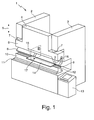
- Fig. 1 shows a processing machine 1 in the form of a press brake, comprising a machine frame with two stands 2, 3 . Between the uprights 2, 3, a top cheek 4 is raised and lowered in a direction illustrated by a double arrow 5 vertical machining direction. The upper cheek 4 merges at its lower end into a pressure bar 6 , which extends over the entire machine front. To raise and lower the upper beam 4 are hydraulic pressing cylinder 7, which engage the pressing bar 6. In an undercut longitudinal groove of the Preßbalkens 6 a strip-like forming die 8 is held in the form of a continuous punch, which ends at the bottom in a Umformkante 9 . The forming die 8 interacts with a forming die 10 designed as a bending die. The latter is mounted on a table 11 of the processing machine 1 and has at its the forming die 8 facing side a V-shaped groove 12 .
- the bending angle measuring device 18 is in Fig.2 shown at a time at which the forming die 8 is in a position in which after folding already a partial relief of the workpiece 14 is done.
- the bending angle measuring device 18 has a first and second plate-shaped support member 19, 20 , on each of which two roller-shaped feeler elements 19a, 19b, 20a, 20b are rotatably mounted on associated slide bearings, of which only those belonging to the feeler elements 19a, 19b of the first support member 19 Slide bearing 21a, 21b in Fig. 2 are shown.
- the distance of the plain bearings 21a, 21b is constant, so that the sensing elements 19a, 19b of the first support member 19 can not perform relative movement to each other.
Abstract
Description
Die Erfindung betrifft eine Bearbeitungsmaschine zum Abkanten von Werkstücken, insbesondere von Blechen, mit einer Umformmatrize und einem mit dieser zusammenwirkenden und in einer Bearbeitungsrichtung relativ zu dieser bewegbaren Umformstempel zur Beaufschlagung des Werkstücks, um zwei Schenkel des Werkstücks unter einem Biegewinkel gegeneinander zu biegen, sowie mit mindestens einem drehbar gelagerten Tastelement einer Biegewinkelmesseinrichtung. Die Erfindung betrifft weiterhin ein Verfahren zum Abkanten von Werkstücken, insbesondere von Blechen, bei dem an dem Werkstück unter Beaufschlagung mit einem Umformstempel und/oder einer mit diesem zusammenwirkenden und in einer Bearbeitungsrichtung relativ zu diesem bewegbaren Umformmatrize zwei Schenkel des Werkstücks unter einem Biegewinkel gegeneinander gebogen werden, wobei für die Messung des Biegewinkels ein drehbar gelagertes Tastelement vorgesehen ist.The invention relates to a processing machine for bending of workpieces, in particular sheets, with a forming die and a cooperating with this and in a processing direction relative to this movable forming die for loading the workpiece to bend two legs of the workpiece at a bending angle against each other, and with at least one rotatably mounted probe element of a bending angle measuring device. The invention furthermore relates to a method for folding workpieces, in particular sheets, in which two legs of the workpiece are bent against one another on the workpiece under the action of a forming punch and / or a cooperating with it and in a machining direction relative to this movable forming die be, with a rotatably mounted probe element is provided for the measurement of the bending angle.
Eine solche Bearbeitungsmaschine und ein solches Verfahren sind beispielsweise aus der
Aus der
Die
Bei den oben beschriebenen Einrichtungen zum Messen des Biegewinkels kann bei ungünstiger Beschaffenheit des Werkstücks, insbesondere wenn eine Verkippung des Werkstücks vorliegt, das mindestens eine Tastelement gegebenenfalls nicht mehr im Blechwinkel an dem Werkstück anliegen, was zu Messfehlern bei der Ermittlung des Biegewinkels führt.In the above-described means for measuring the bending angle can in unfavorable condition of the workpiece, in particular if there is a tilting of the workpiece, the at least one probe element may not more abut the sheet metal angle on the workpiece, which leads to measurement errors in the determination of the bending angle.
Es ist die Aufgabe der vorliegenden Erfindung, eine Bearbeitungsmaschine und ein Verfahren der eingangs genannten Art dahingehend weiterzubilden, dass die Messung des Biegewinkels mit höherer Präzision erfolgen kann.It is the object of the present invention to develop a processing machine and a method of the type mentioned in such a way that the measurement of the bending angle can be done with higher precision.
Diese Aufgabe wird erfindungsgemäß gelöst durch eine Bearbeitungsmaschine der eingangs genannten Art, bei der sich das Tastelement in einer Messstellung nur an einem Schenkel des Werkstücks abstützt und bei einer Veränderung des Biegewinkels eine Rollbewegung entlang des Schenkels des Werkstücks ausführt.This object is achieved by a processing machine of the type mentioned, in which the probe element is supported in a measuring position only on one leg of the workpiece and executes a rolling movement along the leg of the workpiece with a change in the bending angle.
Die Erfinder haben erkannt, dass die Messungenauigkeiten bei der Bestimmung des Biegewinkels im Stand der Technik auf zu starke Reibungskräfte zwischen dem Tastelement und dem Werkstück bei der gleitenden Bewegung des Tastelements entlang des Werkstücks zurückzuführen sind. Erfindungsgemäß wird vorgeschlagen, die Reibung dadurch zu vermindern, dass das Tastelement eine Rollbewegung entlang des Werkstücks ausführt. Hierzu ist es erforderlich, dass sich das Tastelement nur an einem Schenkel des Werkstücks abstützt, da bei einer Abstützung an beiden Schenkeln bei einer Veränderung des Biegewinkels typischer Weise eine gleitende Bewegung des Tastelements erfolgt.The inventors have realized that the measurement inaccuracies in the determination of the bending angle in the prior art are due to excessive frictional forces between the probe element and the workpiece during the sliding movement of the probe element along the workpiece. According to the invention it is proposed to reduce the friction in that the probe element performs a rolling movement along the workpiece. For this purpose, it is necessary that the probe element is supported only on one leg of the workpiece, as in a support on both legs with a change in the bending angle typically occurs a sliding movement of the probe element.
In einer bevorzugten Ausführungsform weist die Bearbeitungsmaschine wenigstens ein Halterungselement auf, an dem das Tastelement drehbar gelagert ist, wobei das Halterungselement in Bearbeitungsrichtung relativ zu dem Umformstempel und/oder der Umformmatrize bewegbar ist. Das Halterungselement wird bei einer Veränderung des Biegewinkels in bzw. entgegen der Bearbeitungsrichtung bewegt. Diese Bewegung des Halterungselements kann zur Bestimmung des Biegewinkels gemessen werden, wie weiter unten ausführlicher dargestellt ist.In a preferred embodiment, the processing machine has at least one holding element on which the feeler element is rotatably mounted, wherein the holding element is movable in the machining direction relative to the forming die and / or the forming die. The support member is moved in a change in the bending angle in or opposite to the machining direction. This movement of the support member may be measured to determine the bend angle, as described in more detail below.
In einer vorteilhaften Weiterbildung ist ein weiteres Tastelement an dem Halterungselement drehbar gelagert, wobei sich das weitere Tastelement in der Messstellung nur an dem anderen Schenkel des Werkstücks abstützt. Mit Hilfe von zwei Tastelementen, die sich an den gegenüberliegenden Schenkeln des Werkstücks abstützen, kann der gesamte Biegewinkel mittels eines einzigen Halterungselements gemessen werden, wenn die relative Lage des Halterungselements zur Umformkante des Umformstempels bekannt ist. Für Details dieser Berechnung sei auf die eingangs erwähnte
Bevorzugt sind das Tastelement und das weitere Tastelement an dem Halterungselement in konstantem Abstand zueinander gelagert. Durch den konstanten Abstand der in der Messstellung an den Schenkeln des Werkstücks anliegenden Tastelemente wird bei einer Veränderung des Biegewinkels eine Bewegung des Halterungselements in Bearbeitungsrichtung erzeugt.Preferably, the probe element and the further probe element are mounted on the support member at a constant distance from each other. Due to the constant distance of the voltage applied to the legs of the workpiece in the measuring position sensing elements, a movement of the support member is generated in the machining direction with a change in the bending angle.
In einer bevorzugten Weiterbildung weist die Bearbeitungsmaschine wenigstens zwei Halterungselemente auf, die in Bearbeitungsrichtung relativ zueinander bewegbar sind. In diesem Fall kann aus der Relativbewegung der Halterungselemente der Biegewinkel berechnet werden, wie in der eingangs genannten
Vorteilhaft ist eine Lagerung des wenigstens einen Halterungselements in einer Führung des Umformstempels zur Bewegung in Bearbeitungsrichtung. Die Führung kann durch einen in dem Umformstempel gebildeten Führungsschlitz realisiert sein, in dem ein Schieber der Halterungseinrichtung in Bearbeitungsrichtung bewegbar geführt ist. Dem Schieber kommt weiterhin die Aufgabe zu, das Halterungselement gegen ein Herausfallen aus dem Führungsschlitz zu sichern.Advantageously, a bearing of the at least one support member in a guide of the forming die for movement in the machine direction. The guide can be realized by a guide slot formed in the forming die, in which a slider of the mounting device is guided movably in the machine direction. The slider is still the task to secure the support member against falling out of the guide slot.
Bevorzugt ist das Halterungselement plattenförmig ausgebildet. In diesem Fall kann die Führung der Halterungseinrichtung an dem Umformstempel eine geringe Weite in Richtung der Umformkante aufweisen, so dass die Umformkante im Bereich des bzw. der Führungsschlitze nur über eine geringe Länge unterbrochen wird und so das mit dem Umformstempel erzielbare Bearbeitungsergebnis in seiner Qualität nicht beeinträchtigt wird.Preferably, the support member is plate-shaped. In this case, the leadership of the support means on the forming die a small width in Have the direction of the forming edge, so that the forming edge is interrupted in the region of the guide slots or only over a small length and so the achievable with the forming die machining result is not affected in its quality.
In einer vorteilhaften Ausführungsform ist das Tastelement als Rolle ausgebildet. Ein rollenförmiges Tastelement ermöglicht ein Abrollen auf dem Schenkel des Werkstücks unter Einhaltung eines konstanten Abstands zwischen der sich an dem Schenkel abstützenden Außenkante der Rolle und deren Drehachse, so dass die Messung des Biegewinkels nicht von der Drehbewegung des Tastelements beeinflusst wird.In an advantageous embodiment, the probe element is designed as a roller. A roller-shaped feeler allows rolling on the leg of the workpiece while maintaining a constant distance between the outer edge of the roller resting on the leg and its axis of rotation, so that the measurement of the bending angle is not influenced by the rotational movement of the probe element.
Die Erfindung betrifft auch ein Verfahren der eingangs genannten Art, bei dem sich das Tastelement in einer Messstellung nur an einem Schenkel des Werkstücks abstützt und bei einer Veränderung des Biegewinkels eine Rollbewegung entlang des Schenkels des Werkstücks ausführt. Ein solches Verfahren ermöglicht eine vorteilhafte Messung des Biegewinkels, da die Reibung des Tastelements an dem Werkstück durch die Rollbewegung gegenüber der im Stand der Technik üblichen Gleitbewegung verringert ist.The invention also relates to a method of the type mentioned, in which the probe element is supported in a measuring position only on one leg of the workpiece and performs a rolling movement along the leg of the workpiece with a change in the bending angle. Such a method enables an advantageous measurement of the bending angle, since the friction of the feeler element on the workpiece is reduced by the rolling movement in relation to the sliding movement usual in the prior art.
In einer vorteilhaften Variante ist das Tastelement an einem Halterungselement drehbar gelagert, das bei der Veränderung des Biegewinkels relativ zu dem Umformstempel und/oder der Umformmatrize in Bearbeitungsrichtung bewegt wird. Die Bewegung des Halterungselements in Bearbeitungsrichtung kann zur Messung des Biegewinkels ausgewertet werden, wie oben beschrieben ist.In an advantageous variant, the feeler element is rotatably mounted on a holding element, which is moved in the machining direction in the change of the bending angle relative to the forming die and / or the forming die. The movement of the support element in the machine direction can be evaluated to measure the bending angle, as described above.
In einer bevorzugten Variante nimmt das Tastelement die Messstellung während einer auf das Biegen des Werkstücks folgenden Entlastung des Werkstücks von dem Umformstempel und/oder von der Umformmatrize ein. Bei der Entlastung des Werkstücks vergrößert sich der Biegewinkel aufgrund von in dem Werkstück wirksamen elastischen Rückstellkräften. Mittels des oben beschriebenen Verfahrens kann eine kontinuierliche Messung des Biegewinkels bei der Entlastung erfolgen, wobei eine vollständige Entlastung des Werkstücks dadurch angezeigt wird, dass der Biegewinkel sich nicht mehr verändert. Wenn der vollständig entlastete Zustand des Werkstücks mittels des Biegewinkelsensors erkannt wurde, kann die Bewegung des Umformstempels bzw. der Umformmatrize gestoppt werden.In a preferred variant, the feeler element assumes the measuring position during a relief of the workpiece following the bending of the workpiece from the forming die and / or from the forming die. When unloading the workpiece, the bending angle increases due to effective in the workpiece elastic restoring forces. By means of the method described above, a continuous measurement of the bending angle during the unloading can take place, whereby a complete relief of the workpiece is indicated by the fact that the bending angle no longer changes. When the fully discharged condition of the Workpiece was detected by means of the bending angle sensor, the movement of the forming die or the forming die can be stopped.
Weitere Vorteile der Erfindung ergeben sich aus der Beschreibung und der Zeichnung. Ebenso können die vorstehend genannten und die noch weiter aufgeführten Merkmale je für sich oder zu mehreren in beliebigen Kombinationen Verwendung finden. Die gezeigten und beschriebenen Ausführungsformen sind nicht als abschließende Aufzählung zu verstehen, sondern haben vielmehr beispielhaften Charakter für die Schilderung der Erfindung.Further advantages of the invention will become apparent from the description and the drawings. Likewise, the features mentioned above and the features listed further can be used individually or in combination in any combination. The embodiments shown and described are not to be understood as exhaustive enumeration, but rather have exemplary character for the description of the invention.
Es zeigen:
- Fig. 1
- eine perspektivische Gesamtansicht einer Ausführungsform einer erfindungsgemäßen Bearbeitungsmaschine, und
- Fig. 2
- einen Schnittdarstellung in der Draufsicht auf die Schnittebene II in
Figur 1
- Fig. 1
- an overall perspective view of an embodiment of a processing machine according to the invention, and
- Fig. 2
- a sectional view in the plan view of the section plane II in
FIG. 1 partially relieved of a plunger workpiece.
In einem Bedienpult 13 sind die Antriebssteuerung der Bearbeitungsmaschine 1 sowie sonstige Einrichtungen zum automatisierten Maschinenbetrieb untergebracht, im Rahmen dessen ein Werkstück 14 in Form einer Blechtafel abgekantet wird. In seiner Ausgangslage ist das Werkstück 14 in
Die Biegewinkelmesseinrichtung 18 ist in
Bei der Rollbewegung der Tastelemente 19a, 19b, 20a, 20b werden die Halterungselemente 19, 20 in Bearbeitungsrichtung 5 verschoben. Um das zweite Halterungselement 20 bei dieser Verschiebung in Bearbeitungsrichtung 5 zu führen, weist dieses an seinem oberen Ende einen Schieber 22 auf, an dem es in einem in dem Umformstempel 8 gebildeten Führungsschlitz 23 verschiebbar gelagert ist. Eine entsprechende Lagerung ist in dem Umformstempel 8 auch für das erste Halterungselement 19 vorgesehen. Bei einer Verringerung des Biegewinkels β wird die Kraft erhöht, welche die Schenkel 15, 16 des Werkstücks 14 auf die Halterungselemente 19, 20 ausüben, so dass diese nach oben gedrückt werden. Erhöht sich der Biegewinkel β, so reduziert sich diese Kraft und die Halterungselemente 19, 20 bewegen sich nach unten. Aus einer Messung der Positionen den Halterungselemente 19, 20 in Bearbeitungsrichtung, die beispielsweise über eine Positionsmessung der Schieber in der Führung des Umformstempels 8 erfolgen kann, sowie durch Differenzbildung der gemessenen Positionen der Halterungselemente 19, 20 kann in einer Auswerteeinrichtung 24 der Biegewinkelmesseinrichtung 18 der Biegewinkel β bestimmt werden, wie ausführlich in der eingangs zitierten
Es versteht sich, dass die Verwendung von Tastelementen, die eine Rollbewegung entlang eines Schenkels eines abgekanteten Werkstücks ausführen, nicht auf die oben beschriebene Bearbeitungsmaschine bzw. den oben beschriebenen Biegewinkelsensor beschränkt sind. Beispielsweise kann der Biegewinkelsensor, sofern zusätzlich die Bewegung des Umlenkstempels in Bearbeitungsrichtung gemessen wird, nur eine einzige Halterungseinrichtung aufweisen. Auch kann auf die oben beschriebene Weise eine Biegewinkelmessung auch bei abgekanteten Werkstücken mit anderen Formen als der oben gezeigten V-Form erfolgen, beispielsweise bei abgekanteten Werkstücken mit U-Form. Auch müssen nicht zwingend wie oben gezeigt an einem Halterungselement zwei Tastelemente vorgesehen sein; vielmehr ist auch die Verwendung von stabförmigen Halteeinrichtungen mit einem einzigen Tastelement möglich.It will be appreciated that the use of sensing elements that perform a rolling movement along a leg of a folded workpiece are not limited to the above-described processing machine or the above-described bending angle sensor. For example, if the movement of the deflection punch in the machining direction is additionally measured, the bending angle sensor can have only a single holding device. Also, in the manner described above, a bending angle measurement can be performed even with beveled workpieces having other shapes than the V-shape shown above, for example, with bent workpieces with U-shape. Also need not necessarily be provided as shown above on a support member two sensing elements; Rather, the use of rod-shaped holding devices with a single probe element is possible.
Claims (11)
dadurch gekennzeichnet,
dass sich das Tastelement (19a, 20a) in einer Messstellung nur an einem Schenkel (15) des Werkstücks (14) abstützt und bei einer Veränderung des Biegewinkels (β) eine Rollbewegung entlang des Schenkels (15) des Werkstücks (14) ausführt.Processing machine (1) for folding workpieces (14), in particular sheets, with a forming die (10) and a forming die (8) cooperating therewith and movable in a processing direction (5) relative to said forming punch (8), in order to bend two legs (15, 16) of the workpiece (14) against one another at a bending angle (β) and with at least one rotatably mounted feeler element (19a, 20a) of a bending angle measuring device (18),
characterized,
that the feeler element (19a, 20a) in a measuring position is supported only on one limb (15) of the workpiece (14) and executes a rolling movement along the limb (15) of the workpiece (14) when the bending angle (β) changes.
dadurch gekennzeichnet,
dass sich das Tastelement (19a, 20a) in einer Messstellung nur an einem Schenkel (15) des Werkstücks (14) abstützt und bei einer Veränderung des Biegewinkels (β) eine Rollbewegung entlang des Schenkels (15) des Werkstücks (14) ausführt.Method for folding workpieces (14), in particular sheets, in which on the workpiece (14) under the action of a forming die (8) and / or cooperating with this and in a processing direction (5) relative to this movable forming die (10 ) are bent two legs (15, 16) of the workpiece (14) at a bending angle (β) against each other, wherein for the measurement of the bending angle (β) a rotatably mounted probe element (19a, 20a) is provided,
characterized,
that the feeler element (19a, 20a) in a measuring position is supported only on one limb (15) of the workpiece (14) and executes a rolling movement along the limb (15) of the workpiece (14) when the bending angle (β) changes.
Priority Applications (1)
| Application Number | Priority Date | Filing Date | Title |
|---|---|---|---|
| EP08001881A EP2085162A1 (en) | 2008-02-01 | 2008-02-01 | Processing machine and process for bending workpieces |
Applications Claiming Priority (1)
| Application Number | Priority Date | Filing Date | Title |
|---|---|---|---|
| EP08001881A EP2085162A1 (en) | 2008-02-01 | 2008-02-01 | Processing machine and process for bending workpieces |
Publications (1)
| Publication Number | Publication Date |
|---|---|
| EP2085162A1 true EP2085162A1 (en) | 2009-08-05 |
Family
ID=39283828
Family Applications (1)
| Application Number | Title | Priority Date | Filing Date |
|---|---|---|---|
| EP08001881A Withdrawn EP2085162A1 (en) | 2008-02-01 | 2008-02-01 | Processing machine and process for bending workpieces |
Country Status (1)
| Country | Link |
|---|---|
| EP (1) | EP2085162A1 (en) |
Cited By (2)
| Publication number | Priority date | Publication date | Assignee | Title |
|---|---|---|---|---|
| WO2013167803A1 (en) * | 2012-05-07 | 2013-11-14 | Aliko Oy Ltd | Method of measuring a workpiece in bending, a measuring device, a measuring carriage as well as a press brake |
| WO2014064615A1 (en) * | 2012-10-22 | 2014-05-01 | Adira, S.A. | Press brake |
Citations (7)
| Publication number | Priority date | Publication date | Assignee | Title |
|---|---|---|---|---|
| DE2044199A1 (en) * | 1970-09-07 | 1972-03-23 | Karl Mengele & Söhne Maschinenfabrik und Eisengießerei, 8870 Günzburg | Programme controlled sheet metal bending - using open tooling |
| NL8105266A (en) | 1981-11-20 | 1983-06-16 | Safan Maschf B V | Angle measuring device for bending press - automatically indicates angle between sides of sheet of metal during bending operation |
| EP0333654A1 (en) * | 1988-03-15 | 1989-09-20 | Hämmerle AG | Angle measuring system |
| JPH05322551A (en) * | 1992-05-20 | 1993-12-07 | Amada Co Ltd | Work bend angle measuring device |
| JPH0929340A (en) * | 1995-07-24 | 1997-02-04 | Amada Co Ltd | Measuring device for bend angle for sheet bending machine |
| EP0775028B1 (en) | 1995-06-12 | 1999-08-18 | Trumpf GmbH & Co | Method and machine for bending workpieces |
| EP1118399A1 (en) | 2000-01-19 | 2001-07-25 | Cornelis Hendricus Liet | Apparatus for measuring the bending angle of a workpiece |
-
2008
- 2008-02-01 EP EP08001881A patent/EP2085162A1/en not_active Withdrawn
Patent Citations (7)
| Publication number | Priority date | Publication date | Assignee | Title |
|---|---|---|---|---|
| DE2044199A1 (en) * | 1970-09-07 | 1972-03-23 | Karl Mengele & Söhne Maschinenfabrik und Eisengießerei, 8870 Günzburg | Programme controlled sheet metal bending - using open tooling |
| NL8105266A (en) | 1981-11-20 | 1983-06-16 | Safan Maschf B V | Angle measuring device for bending press - automatically indicates angle between sides of sheet of metal during bending operation |
| EP0333654A1 (en) * | 1988-03-15 | 1989-09-20 | Hämmerle AG | Angle measuring system |
| JPH05322551A (en) * | 1992-05-20 | 1993-12-07 | Amada Co Ltd | Work bend angle measuring device |
| EP0775028B1 (en) | 1995-06-12 | 1999-08-18 | Trumpf GmbH & Co | Method and machine for bending workpieces |
| JPH0929340A (en) * | 1995-07-24 | 1997-02-04 | Amada Co Ltd | Measuring device for bend angle for sheet bending machine |
| EP1118399A1 (en) | 2000-01-19 | 2001-07-25 | Cornelis Hendricus Liet | Apparatus for measuring the bending angle of a workpiece |
Cited By (3)
| Publication number | Priority date | Publication date | Assignee | Title |
|---|---|---|---|---|
| WO2013167803A1 (en) * | 2012-05-07 | 2013-11-14 | Aliko Oy Ltd | Method of measuring a workpiece in bending, a measuring device, a measuring carriage as well as a press brake |
| WO2014064615A1 (en) * | 2012-10-22 | 2014-05-01 | Adira, S.A. | Press brake |
| US9278384B2 (en) | 2012-10-22 | 2016-03-08 | Adira, S.A. | Press brake |
Similar Documents
| Publication | Publication Date | Title |
|---|---|---|
| DE19521369C2 (en) | Processing machine for forming workpieces | |
| AT503790B1 (en) | STOPPING DEVICE FOR A BEND PRESS | |
| EP1961502B1 (en) | Method and device for bending workpieces | |
| EP2825332B1 (en) | Apparatus and method for straightening metal strip | |
| DE3212070C2 (en) | Roll stand with a device for maintaining the flatness of the rolled material | |
| DE60103423T2 (en) | DEVICE AND METHOD FOR CALIBRATING A MULTI-ROLLING MACHINE | |
| EP2313215B1 (en) | Method for straightening parts in a roller straightening machine | |
| DE102009057726A1 (en) | radial press | |
| EP1761345B1 (en) | Device for impinging the guide surfaces of bearing inserts guided in stand windows of roll stands | |
| EP0560091A1 (en) | Method and device for straightening H-section beams | |
| EP0399296B1 (en) | Automatic adjusting of a universal mill stand after its resetting for new structural shapes | |
| AT508857B1 (en) | METHOD FOR DETERMINING THE THICKNESS OF A WORKPIECE WITH A BENDING MACHINE | |
| EP2092991B1 (en) | Die for a bending press, in particular a press brake and method for bending a workpiece | |
| EP1542816B1 (en) | Bending machine | |
| DE3619648C2 (en) | ||
| EP2085162A1 (en) | Processing machine and process for bending workpieces | |
| DE102005013746B4 (en) | Back corrugated Roll | |
| DE4235971C1 (en) | Press brake | |
| DE60112026T2 (en) | Machine and method for straightening long workpieces with a small cross section | |
| DE3840016A1 (en) | METHOD FOR LEVELING SHEETS, STRIPS, TABLES, PROFILES, CARRIERS ETC. | |
| EP2699365B1 (en) | Method for rolling plates, computer program, data carrier and control device | |
| DE19840563C1 (en) | Press for bending sheet materials | |
| DE2601220C2 (en) | Device for measuring the gap between the horizontal work rolls of a rolling stand | |
| DE609517C (en) | Stretching full workpieces, especially those of rectangular cross-sections, such as plates, tapes, flat bars, etc. | |
| DE2854290C2 (en) |
Legal Events
| Date | Code | Title | Description |
|---|---|---|---|
| PUAI | Public reference made under article 153(3) epc to a published international application that has entered the european phase |
Free format text: ORIGINAL CODE: 0009012 |
|
| AK | Designated contracting states |
Kind code of ref document: A1 Designated state(s): AT BE BG CH CY CZ DE DK EE ES FI FR GB GR HR HU IE IS IT LI LT LU LV MC MT NL NO PL PT RO SE SI SK TR |
|
| AX | Request for extension of the european patent |
Extension state: AL BA MK RS |
|
| AKX | Designation fees paid | ||
| STAA | Information on the status of an ep patent application or granted ep patent |
Free format text: STATUS: THE APPLICATION IS DEEMED TO BE WITHDRAWN |
|
| 18D | Application deemed to be withdrawn |
Effective date: 20100206 |
|
| REG | Reference to a national code |
Ref country code: DE Ref legal event code: 8566 |