EP1117276A2 - Enhanced inverter for powering an EL lamp - Google Patents
Enhanced inverter for powering an EL lamp Download PDFInfo
- Publication number
- EP1117276A2 EP1117276A2 EP01300104A EP01300104A EP1117276A2 EP 1117276 A2 EP1117276 A2 EP 1117276A2 EP 01300104 A EP01300104 A EP 01300104A EP 01300104 A EP01300104 A EP 01300104A EP 1117276 A2 EP1117276 A2 EP 1117276A2
- Authority
- EP
- European Patent Office
- Prior art keywords
- lamp
- diagonal
- current
- scr
- coupled
- Prior art date
- Legal status (The legal status is an assumption and is not a legal conclusion. Google has not performed a legal analysis and makes no representation as to the accuracy of the status listed.)
- Ceased
Links
Images
Classifications
-
- H—ELECTRICITY
- H05—ELECTRIC TECHNIQUES NOT OTHERWISE PROVIDED FOR
- H05B—ELECTRIC HEATING; ELECTRIC LIGHT SOURCES NOT OTHERWISE PROVIDED FOR; CIRCUIT ARRANGEMENTS FOR ELECTRIC LIGHT SOURCES, IN GENERAL
- H05B44/00—Circuit arrangements for operating electroluminescent light sources
-
- Y—GENERAL TAGGING OF NEW TECHNOLOGICAL DEVELOPMENTS; GENERAL TAGGING OF CROSS-SECTIONAL TECHNOLOGIES SPANNING OVER SEVERAL SECTIONS OF THE IPC; TECHNICAL SUBJECTS COVERED BY FORMER USPC CROSS-REFERENCE ART COLLECTIONS [XRACs] AND DIGESTS
- Y02—TECHNOLOGIES OR APPLICATIONS FOR MITIGATION OR ADAPTATION AGAINST CLIMATE CHANGE
- Y02B—CLIMATE CHANGE MITIGATION TECHNOLOGIES RELATED TO BUILDINGS, e.g. HOUSING, HOUSE APPLIANCES OR RELATED END-USER APPLICATIONS
- Y02B20/00—Energy efficient lighting technologies, e.g. halogen lamps or gas discharge lamps
- Y02B20/30—Semiconductor lamps, e.g. solid state lamps [SSL] light emitting diodes [LED] or organic LED [OLED]
Definitions
- This invention relates to a battery operated power supply for an electroluminescent (EL) lamp and, in particular, to an inverter using SCR's as low side switches in an H-bridge.
- EL electroluminescent
- An EL lamp is essentially a capacitor having a dielectric layer between two conductive electrodes, one of which is transparent.
- the dielectric layer may include a phosphor powder or there may be a separate layer of phosphor powder adjacent the dielectric layer.
- the phosphor powder radiates light in the presence of a strong electric field, using very little current. Because an EL lamp is a capacitor, alternating current must be applied to the electrodes to cause the phosphor to glow, otherwise the capacitor charges to the applied voltage, the current through the EL lamp ceases, and the lamp stops producing light.
- an EL lamp In portable electronic devices, automotive displays, and other applications where the power source is a low voltage battery, an EL lamp is powered by an inverter that converts direct current into alternating current. In order for an EL lamp to glow sufficiently, a peak-to-peak voltage in excess of about one hundred and twenty volts is necessary. The actual voltage depends on the construction of the lamp and, in particular, the field strength within the phosphor powder.
- the frequency of the alternating current through an EL lamp affects the life of the EL lamp, with frequencies between 200 hertz and 1000 hertz being preferred. Ionic migration occurs in the phosphor at frequencies below 200 hertz. Above 1000 hertz, the life of the phosphor is inversely proportional to frequency.
- the prior art discloses several types of inverters including an inductive boost circuit having an inductor in series with a switching transistor.
- Current through the inductor causes energy to be stored in a magnetic field around the inductor.
- the induced magnetic field collapses, producing a pulse of high voltage.
- the voltage across the inductor is proportional to L • di / dt .
- a low voltage at high current is converted into a high voltage at low current.
- the voltage on the lamp is pumped up by a series of high voltage pulses from the inverter.
- U.S. Patent 4,527,096 discloses a switching bridge, known as an H-bridge, to alternate the current through the lamp.
- the bridge changes the polarity of the current through the lamp at a low frequency (200-1000 hertz).
- the current paths through the transistors correspond to the current paths through the diodes in a full wave bridge rectifier. That is, the bridge has an AC diagonal, coupled to an EL lamp, and a DC diagonal, coupled to a boost circuit.
- the bridge operates like a double pole, double throw switch, as illustrated in FIG. 1 to produce an alternating current through the EL lamp.
- the transistors coupled to the supply voltage are known as the "high side” switches and the transistors coupled to common are known as the "low side” switches.
- the EL lamp market is very cost sensitive and, for inverters, cost is approximately proportional to the size of a semiconductor die. In a bridge circuit, the peak current determines the size (and cost) of the switching transistors. Cost is also depends upon the kind of transistor used, of which there are several.
- the high side switches of an H-bridge are typically either silicon controlled rectifiers (SCRs) or p-channel metal-oxide-semiconductor, field effect transistors (PMOS FETs).
- the low side switches of an H-bridge are typically NPN-type bipolar junction transistors or NMOS FETs.
- An advantage of MOSFETs is negligible gate current.
- An advantage of an SCR is also negligible gate current.
- Another advantage of an SCR is that an SCR can be made substantially smaller than MOSFETs of equal current capacity.
- An SCR is also far less susceptible to failure due to electrostatic discharge and over voltage than a MOSFET.
- Another object of the invention is to reduce the cost of low power inverters for EL lamps.
- a further object of the invention is to improve the efficiency of low cost inverters for EL lamps.
- Another object of the invention is to reduce the current drawn by a battery power inverter for driving an EL lamp.
- a power supply for an EL lamp includes a boost circuit and four semiconductor switches connected as a bridge having an AC diagonal and a DC diagonal having one end grounded.
- the voltage boost circuit is coupled across the DC diagonal and an electroluminescent lamp is coupled across the AC diagonal of the bridge.
- the two semiconductor switches coupled to ground are SCRs.
- an electroluminescent lamp requires an alternating current for operation.
- a direct current source is all that is available, alternately reversing the connections of an EL lamp and a source of direct current will provide an alternating current.
- the terminals of EL lamp 11 are coupled to respective poles of double pole, double throw (DPDT) switch 12 through resistors 13 and 14.
- the throws of switch 12 are connected to capacitor 16, which stores high voltage DC from a suitable source, not shown.
- FIG. 2 is a schematic of a commercially available inverter that includes the electronic analog of a DPDT switch.
- Inverter 20 includes inductor 21 and switching transistor 22 operating in a well known boost configuration to charge capacitor 23 to a high voltage.
- EL lamp 24 is connected to the AC diagonal of a bridge including SCR 25, SCR 26, switching transistor 27, and switching transistor 28.
- Capacitor 23 is connected across the DC diagonal of the bridge.
- SCR 25 and transistor 28 conduct simultaneously to pass current in a first direction through EL lamp 24.
- SCR 26 and transistor 27 conduct simultaneously to pass current in a second direction through EL lamp 24, alternating with SCR 25 and transistor 28.
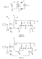
- switching transistors 27 and 28 are replaced with SCRs, as illustrated in FIG. 3.
- SCR 31 and SCR 32 are "low side" switches, coupling the AC diagonal of the bridge to ground or common.
- Transistor 34 is coupled to the gate of SCR 31 and transistor 35 is coupled to the gate of SCR 32.
- the base drive currents for transistors 34 and 35 are dramatically lower than ( 1 / 50 ) the base drive currents for transistors 27 and 28 (FIG. 2). Even including the gate control currents of the SCRs, the total drive current for the low side switches is less than in the prior art.
- the circuit operates in the manner described above, alternating the current through EL lamp 24.
- the SCRs and bipolar transistors are easily implemented with current process technology and the devices require less wafer area, further reducing the cost of the circuit.
- the invention thus provides an improved H-bridge for driving EL lamps that reduces the cost of low power inverters for EL lamps and increases battery life.
Abstract
Description
- This invention relates to a battery operated power supply for an electroluminescent (EL) lamp and, in particular, to an inverter using SCR's as low side switches in an H-bridge.
- An EL lamp is essentially a capacitor having a dielectric layer between two conductive electrodes, one of which is transparent. The dielectric layer may include a phosphor powder or there may be a separate layer of phosphor powder adjacent the dielectric layer. The phosphor powder radiates light in the presence of a strong electric field, using very little current. Because an EL lamp is a capacitor, alternating current must be applied to the electrodes to cause the phosphor to glow, otherwise the capacitor charges to the applied voltage, the current through the EL lamp ceases, and the lamp stops producing light.
- In portable electronic devices, automotive displays, and other applications where the power source is a low voltage battery, an EL lamp is powered by an inverter that converts direct current into alternating current. In order for an EL lamp to glow sufficiently, a peak-to-peak voltage in excess of about one hundred and twenty volts is necessary. The actual voltage depends on the construction of the lamp and, in particular, the field strength within the phosphor powder. The frequency of the alternating current through an EL lamp affects the life of the EL lamp, with frequencies between 200 hertz and 1000 hertz being preferred. Ionic migration occurs in the phosphor at frequencies below 200 hertz. Above 1000 hertz, the life of the phosphor is inversely proportional to frequency.
- The prior art discloses several types of inverters including an inductive boost circuit having an inductor in series with a switching transistor. Current through the inductor causes energy to be stored in a magnetic field around the inductor. When the current is abruptly shut off, the induced magnetic field collapses, producing a pulse of high voltage. The voltage across the inductor is proportional to L • di/dt. Thus, a low voltage at high current is converted into a high voltage at low current. The voltage on the lamp is pumped up by a series of high voltage pulses from the inverter.
- The direct current produced by the inverter must be converted into an alternating current in order to power an EL lamp. U.S. Patent 4,527,096 (Kindlmann) discloses a switching bridge, known as an H-bridge, to alternate the current through the lamp. The bridge changes the polarity of the current through the lamp at a low frequency (200-1000 hertz). In an H-bridge, the current paths through the transistors correspond to the current paths through the diodes in a full wave bridge rectifier. That is, the bridge has an AC diagonal, coupled to an EL lamp, and a DC diagonal, coupled to a boost circuit. The bridge operates like a double pole, double throw switch, as illustrated in FIG. 1 to produce an alternating current through the EL lamp. The transistors coupled to the supply voltage are known as the "high side" switches and the transistors coupled to common are known as the "low side" switches.
- The EL lamp market is very cost sensitive and, for inverters, cost is approximately proportional to the size of a semiconductor die. In a bridge circuit, the peak current determines the size (and cost) of the switching transistors. Cost is also depends upon the kind of transistor used, of which there are several.
- The high side switches of an H-bridge are typically either silicon controlled rectifiers (SCRs) or p-channel metal-oxide-semiconductor, field effect transistors (PMOS FETs). The low side switches of an H-bridge are typically NPN-type bipolar junction transistors or NMOS FETs. An advantage of MOSFETs is negligible gate current. An advantage of an SCR is also negligible gate current. Another advantage of an SCR is that an SCR can be made substantially smaller than MOSFETs of equal current capacity. An SCR is also far less susceptible to failure due to electrostatic discharge and over voltage than a MOSFET.
- Some commercially available inverters use NMOS low side switches. Others use NPN bipolar junction transistors as low side switches. Although smaller than FETs of comparable current capability, there are two important drawbacks to bipolar junction transistors, they require significant base current and they must be sized for peak lamp current, causing them to be substantially larger than the equivalent SCR.
- In view of the foregoing, it is therefore an object of the invention to provide an improved H-bridge for driving EL lamps.
- Another object of the invention is to reduce the cost of low power inverters for EL lamps.
- A further object of the invention is to improve the efficiency of low cost inverters for EL lamps.
- Another object of the invention is to reduce the current drawn by a battery power inverter for driving an EL lamp.
- The foregoing objects are achieved in the invention in which a power supply for an EL lamp includes a boost circuit and four semiconductor switches connected as a bridge having an AC diagonal and a DC diagonal having one end grounded. The voltage boost circuit is coupled across the DC diagonal and an electroluminescent lamp is coupled across the AC diagonal of the bridge. The two semiconductor switches coupled to ground are SCRs.
- A more complete understanding of the invention can be obtained by considering the following detailed description in conjunction with the accompanying drawings, in which:
- FIG. 1 illustrates the operation of an H-bridge inverter;
- FIG. 2 is a schematic of a commercially available inverter having an H-bridge output; and
- FIG. 3 is a schematic of an inverter constructed in accordance with a preferred embodiment of the invention.
-
- As noted above, an electroluminescent lamp requires an alternating current for operation. When a direct current source is all that is available, alternately reversing the connections of an EL lamp and a source of direct current will provide an alternating current. As illustrated in FIG. 1, the terminals of
EL lamp 11 are coupled to respective poles of double pole, double throw (DPDT) switch 12 throughresistors switch 12 are connected tocapacitor 16, which stores high voltage DC from a suitable source, not shown. Whenswitch 12 is closed to the left, current flows from the upper electrode oflamp 11 to the lower electrode and flows in the opposite direction when the switch is closed to the right. - FIG. 2 is a schematic of a commercially available inverter that includes the electronic analog of a DPDT switch.
Inverter 20 includesinductor 21 and switchingtransistor 22 operating in a well known boost configuration to chargecapacitor 23 to a high voltage.EL lamp 24 is connected to the AC diagonal of abridge including SCR 25,SCR 26, switchingtransistor 27, and switchingtransistor 28.Capacitor 23 is connected across the DC diagonal of the bridge.SCR 25 andtransistor 28 conduct simultaneously to pass current in a first direction throughEL lamp 24.SCR 26 andtransistor 27 conduct simultaneously to pass current in a second direction throughEL lamp 24, alternating withSCR 25 andtransistor 28. - Any current not contributing to the production of light is wasted and decreases the efficiency of the circuit. For devices operating from a battery, wasted current shortens battery life. The base drive current for
transistor 22 is unrecoverable and unavoidable. A field effect transistor could be used instead but the cost of a FET is significantly higher than that of a bipolar transistor. - In accordance with the invention, switching
transistors SCR 31 andSCR 32 are "low side" switches, coupling the AC diagonal of the bridge to ground or common.Transistor 34 is coupled to the gate ofSCR 31 andtransistor 35 is coupled to the gate ofSCR 32. The base drive currents fortransistors transistors 27 and 28 (FIG. 2). Even including the gate control currents of the SCRs, the total drive current for the low side switches is less than in the prior art. - The circuit operates in the manner described above, alternating the current through
EL lamp 24. The SCRs and bipolar transistors are easily implemented with current process technology and the devices require less wafer area, further reducing the cost of the circuit. - The invention thus provides an improved H-bridge for driving EL lamps that reduces the cost of low power inverters for EL lamps and increases battery life.
- Having thus described the invention, it will be apparent to those of skill in the art that various modifications can be made within the scope of the invention.
Claims (3)
- A power supply for an electroluminescent lamp, said power supply comprising:a voltage boost circuit;four semiconductor switches connected as a bridge having an AC diagonal and a DC diagonal, wherein said voltage boost circuit is coupled to said DC diagonal and said AC diagonal is adapted for connection to said electroluminescent lamp;wherein each semiconductor switch includes an SCR.
- A power supply for an electroluminescent lamp, said power supply comprising:a voltage boost circuit;a first pair of series connected, semiconductor switches including a first high side switch and a first low side switch;a second pair of series connected, semiconductor switches including a second high side switch and a second low side switch;wherein said high side switches are coupled to said boost circuit, said low side switches are coupled to ground and wherein each low side switch includes an SCR.
- The power supply as set forth in claim 2 wherein each low side switch further includes a bipolar transistor driver coupled to the gate of the SCR, wherein the base drive current of the bipolar transistor plus the gate drive current of the SCR is less than the drive current for a bipolar transistor alone as a low side switch.
Applications Claiming Priority (2)
| Application Number | Priority Date | Filing Date | Title |
|---|---|---|---|
| US09/482,675 US6204609B1 (en) | 2000-01-13 | 2000-01-13 | Enhanced inverter for powering an EL lamp |
| US482675 | 2000-01-13 |
Publications (2)
| Publication Number | Publication Date |
|---|---|
| EP1117276A2 true EP1117276A2 (en) | 2001-07-18 |
| EP1117276A3 EP1117276A3 (en) | 2004-03-17 |
Family
ID=23916976
Family Applications (1)
| Application Number | Title | Priority Date | Filing Date |
|---|---|---|---|
| EP01300104A Ceased EP1117276A3 (en) | 2000-01-13 | 2001-01-08 | Enhanced inverter for powering an EL lamp |
Country Status (2)
| Country | Link |
|---|---|
| US (1) | US6204609B1 (en) |
| EP (1) | EP1117276A3 (en) |
Families Citing this family (8)
| Publication number | Priority date | Publication date | Assignee | Title |
|---|---|---|---|---|
| US6376934B1 (en) * | 1999-08-18 | 2002-04-23 | Sipex Corporation | Voltage waveform generator |
| US6204609B1 (en) * | 2000-01-13 | 2001-03-20 | Durel Corporation | Enhanced inverter for powering an EL lamp |
| US6452439B1 (en) * | 2001-05-07 | 2002-09-17 | International Business Machines Corporation | Inductive voltage spike generator with diode shunt |
| JP4080775B2 (en) * | 2001-07-06 | 2008-04-23 | セイコーインスツル株式会社 | EL drive circuit, control method for EL drive circuit, and electronic apparatus |
| JP4060617B2 (en) * | 2002-03-13 | 2008-03-12 | 株式会社小糸製作所 | Discharge lamp lighting circuit |
| WO2003079733A1 (en) * | 2002-03-19 | 2003-09-25 | Koninklijke Philips Electronics N.V. | Driver circuit for an electroluminescent lamp |
| US7843140B2 (en) * | 2005-10-27 | 2010-11-30 | Rogers Corporation | AC switch with zero off current for EL panel |
| CA2719014A1 (en) * | 2008-03-26 | 2009-10-01 | Enphase Energy, Inc. | Method and apparatus for resetting silicon controlled rectifiers in a hybrid bridge |
Citations (5)
| Publication number | Priority date | Publication date | Assignee | Title |
|---|---|---|---|---|
| US5712533A (en) * | 1994-05-26 | 1998-01-27 | Eta Sa Fabriques D'ebauches | Power supply circuit for an electroluminescent lamp |
| JPH11233256A (en) * | 1998-02-12 | 1999-08-27 | Citizen Electronics Co Ltd | El drive circuit |
| EP0971565A1 (en) * | 1998-07-08 | 2000-01-12 | Seiko Precision Inc. | Drive circuit for EL element |
| US6204609B1 (en) * | 2000-01-13 | 2001-03-20 | Durel Corporation | Enhanced inverter for powering an EL lamp |
| GB2354380A (en) * | 1999-07-13 | 2001-03-21 | Ultra Electronics Ltd | Power supply circuit for electroluminescent device |
Family Cites Families (7)
| Publication number | Priority date | Publication date | Assignee | Title |
|---|---|---|---|---|
| US4527096A (en) * | 1984-02-08 | 1985-07-02 | Timex Corporation | Drive circuit for capacitive electroluminescent panels |
| US5349269A (en) * | 1993-03-29 | 1994-09-20 | Durel Corporation | Power supply having dual inverters for electroluminescent lamps |
| US5313141A (en) * | 1993-04-22 | 1994-05-17 | Durel Corporation | Three terminal inverter for electroluminescent lamps |
| US5418434A (en) * | 1994-08-18 | 1995-05-23 | Timex Corporation | Voltage-boosting circuit for an electroluminescent lamp driver |
| US5821701A (en) * | 1996-05-21 | 1998-10-13 | Teggatz; Ross | Boost regulator circuit with stoarge capacitor for reduced power consumption |
| US6043610A (en) * | 1998-07-16 | 2000-03-28 | Durel Corporation | Battery operated power supply including a low level boost and a high level boost |
| US6091164A (en) * | 1998-10-29 | 2000-07-18 | Durel Corporation | Single inverter with dual boost |
-
2000
- 2000-01-13 US US09/482,675 patent/US6204609B1/en not_active Expired - Fee Related
-
2001
- 2001-01-08 EP EP01300104A patent/EP1117276A3/en not_active Ceased
Patent Citations (5)
| Publication number | Priority date | Publication date | Assignee | Title |
|---|---|---|---|---|
| US5712533A (en) * | 1994-05-26 | 1998-01-27 | Eta Sa Fabriques D'ebauches | Power supply circuit for an electroluminescent lamp |
| JPH11233256A (en) * | 1998-02-12 | 1999-08-27 | Citizen Electronics Co Ltd | El drive circuit |
| EP0971565A1 (en) * | 1998-07-08 | 2000-01-12 | Seiko Precision Inc. | Drive circuit for EL element |
| GB2354380A (en) * | 1999-07-13 | 2001-03-21 | Ultra Electronics Ltd | Power supply circuit for electroluminescent device |
| US6204609B1 (en) * | 2000-01-13 | 2001-03-20 | Durel Corporation | Enhanced inverter for powering an EL lamp |
Non-Patent Citations (1)
| Title |
|---|
| PATENT ABSTRACTS OF JAPAN vol. 1999, no. 13, 30 November 1999 (1999-11-30) -& JP 11 233256 A (CITIZEN ELECTRONICS CO LTD), 27 August 1999 (1999-08-27) * |
Also Published As
| Publication number | Publication date |
|---|---|
| EP1117276A3 (en) | 2004-03-17 |
| US6204609B1 (en) | 2001-03-20 |
Similar Documents
| Publication | Publication Date | Title |
|---|---|---|
| US6043610A (en) | Battery operated power supply including a low level boost and a high level boost | |
| JP3002543B2 (en) | Three-terminal inverter for electroluminescent lamps | |
| US5349269A (en) | Power supply having dual inverters for electroluminescent lamps | |
| EP1300054B1 (en) | El driver with lamp discharge monitor | |
| US6462485B1 (en) | EL driver for small semiconductor die | |
| US7355351B2 (en) | Circuit arrangement having a converter without a transformer but with an inductor for the pulsed operation of dielectric barrier discharge lamps | |
| US6204609B1 (en) | Enhanced inverter for powering an EL lamp | |
| US6597123B1 (en) | Inverter for driving EL lamp and liquid crystal display | |
| US6091164A (en) | Single inverter with dual boost | |
| US5896287A (en) | Bridge-type direct current boost converter for driving a capacitive load | |
| CN100521840C (en) | H-bridge driver for electroluminescent lamp that reduces audible noise | |
| WO2006062936A2 (en) | Single output el driver producing reduced current spikes | |
| US6605976B2 (en) | Half-bridge circuit | |
| KR100565023B1 (en) | Control Circuit for a DC Motor | |
| US6259619B1 (en) | EL driver with reduced pin count | |
| US6297597B1 (en) | EL driver with low side current mirrors | |
| CA2398208A1 (en) | Electronic ballast circuit for operating a high intensity discharge lamp | |
| JP3356907B2 (en) | Electroluminescence drive circuit | |
| KR100341700B1 (en) | Electronic supply for igniting a high-pressure discharge lamp | |
| JPH11346481A (en) | Bridge-type dc boost converter for drive of capacitive load |
Legal Events
| Date | Code | Title | Description |
|---|---|---|---|
| PUAI | Public reference made under article 153(3) epc to a published international application that has entered the european phase |
Free format text: ORIGINAL CODE: 0009012 |
|
| 17P | Request for examination filed |
Effective date: 20010122 |
|
| AK | Designated contracting states |
Kind code of ref document: A2 Designated state(s): AT BE CH CY DE DK ES FI FR GB GR IE IT LI LU MC NL PT SE TR |
|
| AX | Request for extension of the european patent |
Free format text: AL;LT;LV;MK;RO;SI |
|
| PUAL | Search report despatched |
Free format text: ORIGINAL CODE: 0009013 |
|
| AK | Designated contracting states |
Kind code of ref document: A3 Designated state(s): AT BE CH CY DE DK ES FI FR GB GR IE IT LI LU MC NL PT SE TR |
|
| AX | Request for extension of the european patent |
Extension state: AL LT LV MK RO SI |
|
| AKX | Designation fees paid |
Designated state(s): DE FI FR GB SE |
|
| 17Q | First examination report despatched |
Effective date: 20050426 |
|
| STAA | Information on the status of an ep patent application or granted ep patent |
Free format text: STATUS: THE APPLICATION HAS BEEN REFUSED |
|
| 18R | Application refused |
Effective date: 20060304 |