EP1117229A1 - A method for creating forwarding lists for cluster networking - Google Patents
A method for creating forwarding lists for cluster networking Download PDFInfo
- Publication number
- EP1117229A1 EP1117229A1 EP01300197A EP01300197A EP1117229A1 EP 1117229 A1 EP1117229 A1 EP 1117229A1 EP 01300197 A EP01300197 A EP 01300197A EP 01300197 A EP01300197 A EP 01300197A EP 1117229 A1 EP1117229 A1 EP 1117229A1
- Authority
- EP
- European Patent Office
- Prior art keywords
- packet
- forwarding list
- node
- service
- bucket
- Prior art date
- Legal status (The legal status is an assumption and is not a legal conclusion. Google has not performed a legal analysis and makes no representation as to the accuracy of the status listed.)
- Granted
Links
Images


Classifications
-
- H—ELECTRICITY
- H04—ELECTRIC COMMUNICATION TECHNIQUE
- H04L—TRANSMISSION OF DIGITAL INFORMATION, e.g. TELEGRAPHIC COMMUNICATION
- H04L67/00—Network arrangements or protocols for supporting network services or applications
- H04L67/01—Protocols
- H04L67/10—Protocols in which an application is distributed across nodes in the network
- H04L67/1001—Protocols in which an application is distributed across nodes in the network for accessing one among a plurality of replicated servers
- H04L67/1004—Server selection for load balancing
- H04L67/1008—Server selection for load balancing based on parameters of servers, e.g. available memory or workload
-
- H—ELECTRICITY
- H04—ELECTRIC COMMUNICATION TECHNIQUE
- H04L—TRANSMISSION OF DIGITAL INFORMATION, e.g. TELEGRAPHIC COMMUNICATION
- H04L67/00—Network arrangements or protocols for supporting network services or applications
- H04L67/01—Protocols
- H04L67/10—Protocols in which an application is distributed across nodes in the network
- H04L67/1001—Protocols in which an application is distributed across nodes in the network for accessing one among a plurality of replicated servers
- H04L67/1004—Server selection for load balancing
- H04L67/1019—Random or heuristic server selection
-
- H—ELECTRICITY
- H04—ELECTRIC COMMUNICATION TECHNIQUE
- H04L—TRANSMISSION OF DIGITAL INFORMATION, e.g. TELEGRAPHIC COMMUNICATION
- H04L67/00—Network arrangements or protocols for supporting network services or applications
- H04L67/01—Protocols
- H04L67/10—Protocols in which an application is distributed across nodes in the network
- H04L67/1001—Protocols in which an application is distributed across nodes in the network for accessing one among a plurality of replicated servers
- H04L67/1004—Server selection for load balancing
- H04L67/1023—Server selection for load balancing based on a hash applied to IP addresses or costs
-
- H—ELECTRICITY
- H04—ELECTRIC COMMUNICATION TECHNIQUE
- H04L—TRANSMISSION OF DIGITAL INFORMATION, e.g. TELEGRAPHIC COMMUNICATION
- H04L9/00—Cryptographic mechanisms or cryptographic arrangements for secret or secure communications; Network security protocols
- H04L9/40—Network security protocols
-
- H—ELECTRICITY
- H04—ELECTRIC COMMUNICATION TECHNIQUE
- H04L—TRANSMISSION OF DIGITAL INFORMATION, e.g. TELEGRAPHIC COMMUNICATION
- H04L67/00—Network arrangements or protocols for supporting network services or applications
- H04L67/01—Protocols
- H04L67/10—Protocols in which an application is distributed across nodes in the network
- H04L67/1001—Protocols in which an application is distributed across nodes in the network for accessing one among a plurality of replicated servers
- H04L67/10015—Access to distributed or replicated servers, e.g. using brokers
-
- H—ELECTRICITY
- H04—ELECTRIC COMMUNICATION TECHNIQUE
- H04L—TRANSMISSION OF DIGITAL INFORMATION, e.g. TELEGRAPHIC COMMUNICATION
- H04L67/00—Network arrangements or protocols for supporting network services or applications
- H04L67/01—Protocols
- H04L67/10—Protocols in which an application is distributed across nodes in the network
- H04L67/1001—Protocols in which an application is distributed across nodes in the network for accessing one among a plurality of replicated servers
- H04L67/1004—Server selection for load balancing
- H04L67/1017—Server selection for load balancing based on a round robin mechanism
Definitions
- the present invention relates to clustered computer systems with multiple nodes that provide services in a scalable manner. More specifically, the present invention relates to a method and an apparatus that uses forwarding lists of existing connections to forward packets to server nodes of a cluster.
- a number of characteristics are desirable. It is desirable for such a system to be efficient in order to accommodate as much traffic as possible with a minimal amount of response time. It is desirable for such a system to be "scalable," so that additional server nodes can be added and balancing between the nodes can be modifiable to provide a service as demand for the service increases. In doing so, it is important to ensure that response time does not increase as additional server nodes are added. It is also desirable for such a system to be constantly available, even when individual server nodes or communication pathways between server nodes fail.
- a system that distributes traffic between multiple server nodes typically performs a number of tasks. Upon receiving a packet, the system performs a lookup to determine whether the service the packet is meant for is a scalable service.
- the system distributes workload involved in providing the service between the server nodes that are able to provide the service. What is needed are a method and an apparatus for distributing workload between server nodes that is efficient, scalable, and highly available and allows client affinity.
- the packet is forwarded to the server node.
- the conventional technique of using a remote procedure call (RPC) or an interface definition language (IDL) call to forward a packet typically involves traversing an Internet Protocol (IP) stack from an RPC/IDL endpoint to a transport driver at the sender side, and then traversing another IP stack on the receiver side, from a transport driver to an RPC/IDL endpoint. Note that traversing these two IP stacks is highly inefficient. What is needed are a method and an apparatus for forwarding packets to server nodes that is efficient, scalable, and highly available.
- IP Internet Protocol
- a scalable service that is transparent to an application. This transparency allows one to write an application that can run on a scalable service or a non-scalable service. Such an application is typically easier to write, since it does not need to take into account scalability.
- a scalable service that is transparent to the client application would tend to be able to use existing client applications. Scalable networks when running such applications may run the application on a node of the scalable service. If a series of connections are required between the server and client, one way of doing this is having the nodes in the scalable service have shared memory so that, if the client messages went to different nodes, any node on the system would be able to process the message by accessing the shared memory.
- SolarisTM is manufactured by Sun MicrosystemsTM of Palo Alto California.
- One embodiment of the present invention provides a system that uses forwarding lists so that if the workload between nodes is redistributed, packets from an existing connection continue to be directed to the same server node until the connection is terminated.
- Another embodiment of the present invention provides a method of distributing packets to server nodes in a cluster of nodes, comprising the steps of: receiving a packet at an interface node in the cluster of nodes, the packet including a source address; matching the packet with a service object; performing a function that maps the source address to a bucket of a plurality of buckets in a packet distribution table associated service object matched with the packet, the buckets containing identifiers for server nodes in the cluster of nodes; determining if the source address matches a listing in a forwarding list; if there is a match sending the packet to a node indicated by the match; and, if there is not a match sending the packet to a node identified by the bucket into which the source address of the packet is mapped.
- a computer readable storage medium which may be any device or medium that can store code and/or data for use by a computer system.
- the transmission medium may include a communications network, such as the Internet.
- FIG. 1 illustrates a clustered computing system 100 coupled to clients 121-123 through networks 120 in accordance with an embodiment of the present invention.
- Clients 121-123 can include any node on networks 120, including computational capability and including a mechanism for communicating across networks 120.
- Clients 121-123 communicate with clustered computing system 100 by sending packets to clustered computing system 100 in order to request services from clustered computing system 100.
- Networks 120 can include any type of wire or wireless communication channel capable of coupling together computing nodes. This includes, but is not limited to, a local area network, a wide area network, or a combination of networks. In one embodiment of the present invention, networks 120 include the Internet.
- Clustered computing system 100 includes a set of nodes that are coupled together through a communication channel (not shown). These nodes include server nodes 102 and 104 as well as interface node/server node 103. Nodes 102-104 are coupled to storage system 110. Storage system 110 provides archival storage for code and/or data that is manipulated by nodes 102-104. This archival storage may include, but is not limited to, magnetic storage, optical storage, flash memory, ROM, EPROM, EEPROM, and battery-backed-up RAM.
- Nodes 102-104 are coupled together through a private interconnect with redundant pathways (not shown).
- nodes 102-104 can be interconnected through a communication mechanism adhering to the Ethernet or a scalable coherent interconnect (SCI) standards.
- a path manager operates on all of the nodes in clustered computing system 100. This path manager knows about the interconnect topology and monitors the status of pathways. The path manager also provides an interface registry to which other components interested in the status of the interconnect can register. This provides a mechanism for the path manager to make callbacks to the interested components when the status of a path changes, if a new path comes up, or if a path is removed.
- Nodes 102-104 are coupled to networks 120 through a highly available addressing system 108.
- Highly available addressing system 108 allows interface nodes within clustered computing system 100 to be addressed from networks 120 in a "highly-available" manner so that if an interface node fails, a backup secondary interface node is able to take its place without the failure being visible to clients 121-123.
- interface node 103 can host one or more shared IP addresses for clustered computing system 100.
- more than one node in clustered computing system 100 can act as a standby interface node for a given service. This allows a backup interface node to take over for an interface node that fails.
- nodes 102-104 within clustered computing system 100 can provide scalable services. Each scalable service behaves as a single logical entity from the view of clients 121-123. Also note that clients 121-123 can communicate with clustered computing system 100 through a transmission control protocol (TCP) connection or a user datagram protocol (UDP) session.
- TCP transmission control protocol
- UDP user datagram protocol
- a service is said to be "scalable” if increased load on the service is matched with an increase in hardware and server instances that are performing the service or by changing the balancing distribution between nodes. For example, a web server is scalable if additional load on the web server is matched by a corresponding increase in server nodes to process the additional load, or by a change in the distribution of the load across the hardware and server instances that are performing the service.
- Clustered computing system 100 operates generally as follows. As packets arrive at interface node 103 from clients 121-123, a service is selected for the packet based on the destination address in the packet. Next, a server instance is selected for the packet based upon the source address of the packet as well as the destination address of the packet. Note that the system ensures that packets belonging to the same TCP connection are sent to the same server instance. Finally, the packet is sent to the selected server instance.
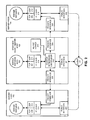
- FIG. 2 illustrates the internal structure of interface node 103 and server nodes 102 and 104 within clustered computing system 100 (FIG. 1) in accordance with an embodiment of the present invention.
- Client 121 sends packets to clustered computing system 100 in order to receive a service from clustered computing system 100. These packets enter public interface 221 within interface node 103 in clustered computing system 100.
- Public interface 221 can include any type of interface that is able to receive packets from networks 120.
- cluster networking multiplexer 218 As packets arrive at interface node 103 via public interface 221, they pass through cluster networking multiplexer 218.
- Cluster networking multiplexer 218 forwards the packets to various nodes within clustered computing system 100 based upon load balancing policies and other considerations. In making forwarding decisions, cluster networking multiplexer 218 retrieves data from highly available PDT server 230. The structure of this data is described in more detail below with reference to FIG. 3. Note that HA PDT server 230 may be replicated across multiple nodes of clustered computing system 100 so that in case a node fails, a backup node can take over for it to maintain availability for HA PDT server 230.
- Packets are forwarded from interface node 103 to other nodes in the clustered computing system 100, including server nodes 102 and 104, through private interfaces 224 and 225.
- Private interfaces 224 and 225 can include any interface that can handle communications between nodes within clustered computing system 100. For example, packets can be forwarded from private interface 224 to private interface 226 on server node 104, or from private interface 225 to private interface 228 on server node 102. Note that private interfaces 224 and 225 do not handle communications with entities outside of clustered computing system 100.
- private interface 224 and public interface 221 share some of the same communication hardware and send messages down some of the same physical data paths.
- private interface 224 and public interface 221 may also share some of the same interface software.
- private interface 224 and public interface 221 need not represent different communication mechanisms. Therefore, the distinction between private interface 224 and public interface 221 can be merely a distinction between whether the communications are with an entity outside of clustered computing system 100, or with an entity within clustered computing system 100.
- Packets entering server nodes 102 and 104 pass through IP stacks 214 and 216, respectively.
- Cluster networking multiplexer 218 can also send packets to IP stack 215 within interface node/server node 103, because node 103 is also able to act as a server.
- packets pass through IP stack 214 into TCP module 206, which supports TCP connections, or into UDP module 210, which supports UDP sessions.
- IP stack 215 into TCP module 207 or into UDP module 211.
- packets pass through IP stack 216 into TCP module 208 or into UDP module 212.
- the packets are processed by server instances 201-203 on nodes 102-104, respectively.
- Return communications for server nodes 102 and 104 do not follow the same path. Return communication from server node 102 pass down through IP stack 214, through public interface 220 and then to client 121. Similarly, return communications from server node 104 pass down through IP stack 216, through public interface 222 and then to client 121. This frees interface node 103 from having to handle return communication traffic.
- this return communication mechanism can provide load balancing for the return traffic.
- web servers typically receive navigational commands from a client, and in response send large volumes of web page content (such as graphical images) back to the client.
- web page content such as graphical images
- a server node such as a proxy node (a non-global interface node for that IP address), such as server node 104
- shared IP addresses are hosted on the "loopback interface" of server node 104.
- the loopback interface is defined within the UNIX and SOLARISTM operating system standards. SolarisTM is a trademark of Sun Microsystems, Inc. of Palo Alto, California).
- FIG. 3 illustrates data structures associated with a scalable service in accordance with an embodiment of the present invention.
- HA PDT server 230 contains at least one service group 302.
- the service group 302 can be associated with a group of service objects (identified by a unique protocol, service IP address, and service port number combination) that share a load balancing policy.
- service group 302 may have at least one associated secondary version on another node and possible spares for fault-tolerance purposes. Any changes to service group 302 may be checkpointed to this secondary version so that if the node containing the primary version of service group 302 fails, the node containing the secondary version can take over.
- Service group 302 may be also associated with a number of "slave" versions of the service group located on other nodes in clustered computing system 100. This allows the other nodes to more quickly access the data within service group 302. Any changes to service group 302 may be propagated to the corresponding slave versions. Slave versions may be derivations of the master service group, not having all of the information in the master service group.
- Service group 302 includes a number of data structures, including packet distribution table (PDT) 304, load balancing policy 306, a service object 308, configuration node list 310, and instance node list 312.
- PTT packet distribution table
- load balancing policy 306 a service object 308
- configuration node list 310 a service object 308
- Configuration node list 310 contains a list of server nodes within clustered computing system 100 that can provide the services associated with service group 302.
- the service object 308 obtains configuration data from the configuration node list 310.
- Instance node list 312 contains a list of the nodes that are actually being used to provide these services.
- the service object 308 contains information related to a service (identified by a unique protocol, service IP address, and service port number combination) associated with the service group 302. There may be more than one service object in each service group. Each service (identified by a unique protocol, service IP address, and service port number combination) associated with the service group is associated with one service object (identified by the same unique protocol, service IP address, and service port number combination as the associated service) in the service group.
- Load balancing policy 306 contains a description of a load balancing policy that is used to distribute packets between nodes involved in providing services associated with service group 302.
- the load balancing policy 306 may specify the load balancing policy type and load balancing policy weights.
- the described embodiment of the invention uses at least three types of load balancing policies, which include 1) a non-affinity policy, 2) a client affinity policy, and 3) a wild card client affinity policy.
- the weights may specify that a certain percentage of traffic is sent to a certain node.
- PDT 304 is used to implement the load balancing policy.
- PDT 304 includes entries that are populated with identifiers for nodes that are presently able to receive packets for the services associated with service group 302.
- the system hashes the client address and potentially the client port according to the load balancing policy of the PDT 304 as described in more detail below. This hashing selects a particular entry in PDT 304, and this entry identifies a server node within clustered computing system 100.
- the frequency of entries can be varied to achieve different distributions of traffic between different server nodes. For example, a high performance server node that is able to process a large amount of traffic can be given more entries in PDT 304 than a slower server node that is able to process less traffic. In this way, the high-performance server node will, on average, receive more traffic than the slower server node.
- FIG- 9 illustrates how a PDT server is checkpointed to a slave PDT server and a secondary PDT server in accordance with an embodiment of the present invention.
- the system maintains a primary/master PDT server 912 on node 910.
- the state of primary/master PDT server 912 is checkpointed to secondary PDT server 904 on node 902 so that secondary PDT server 904 is kept consistent with primary/master PDT server 912. In this way, if primary/master PDT server 912 fails, secondary PDT server 904 is able to take its place.
- a slave PDT server 908 is maintained on interface node 906 for performance reasons (not high availability reasons). In this case, most of the state of primary/master PDT server 912 is checkpointed to slave PDT server 908 in interface node 906. This allows interface node 906 to access the information related to packet forwarding locally, within slave PDT server 908, without having to communicate with node primary/master PDT server 912 on node 910.
- Master service groups are maintained in the primary/master PDT server 912, where the master service groups have master service objects. Secondary copies of the master service groups and master service objects are maintained in the secondary PDT server 904. Slave copies of the master service group, which are subsets or derivations of the master service group, and slave copies of the master service objects, which are subsets or derivations of the master service objects, are maintained in the slave PDT server 908.
- data when it is disclosed that data is being read from a service group or written to a service group, it may actually be written to a master, a secondary copy, or slave copy of the master service group.
- data when it is disclosed that data is being read from a service object or written to a service object, it may actually be written to a master, a secondary copy, or slave copy of the master service object.
- FIG. 4 illustrates how an IP packet 400 is encapsulated with a DLPI header 402 in accordance with an embodiment of the present invention.
- DLPI header 402 is attached to the head of IP packet 400.
- DLPI header 402 includes the medium access control (MAC) address of the destination server node 104.
- MAC medium access control
- IP packet 400 includes a destination address 404 that, in the preferred embodiment, specifies a protocol, a service IP address, and a service port number of a service that is hosted by interface node 103, as well as the source address 406 that, in the preferred embodiment, specifies a client IP address and client port number for a client that sent the packet.
- FIG. 5A is a flow chart illustrating the process of configuring a load balancing system in accordance with an embodiment of the present invention.
- the system starts by configuring a scalable service group (step 501). This involves creating a service group (step 502) for the scalable service group and specifying a load balancing policy type for the service group (step 503).
- load balancing policies which include 1) a non-affinity policy, 2) a client affinity policy, and 3) a wild card client affinity policy.
- non-affinity policies such as a weighted or round robin load balancing policy.
- load balancing policy weights are initially set at a default of equal weighting for each node.
- the weights may be set differently later at step 508.
- a service object is created for a particular service specified by a unique protocol, service IP address and port number (step 504) and is assigned to a service group.
- the service identified by the service object is placed in either a first service list hash table or a second service list hash table, which lists all services identified by all service objects in all service groups. Services that are identified by service objects in service groups, that do not have wild card client affinity load balancing policy, are placed in the first service list hash table. Services identified by service objects in service groups with a wild card client affinity load balancing policy type are place in the second service list hash table.
- Configuring a scalable service group also involves initializing a configuration node list 310 (step 506) to indicate which server nodes within clustered computing system 100 are able to provide the service group, and setting load balancing policy weights 306 for the service group to change the balance between the nodes from the default setting (step 508). Note that a particular load balancing policy can specify weights for the particular server nodes.
- FIG. 5B is a flow chart illustrating the process of service activation/deactivation in accordance with an embodiment of the present invention. This process happens whenever an instance is started or stopped, or whenever a node fails. For every scalable service group, the system examines every node on the configuration node list 310. If the node matches running version of the scalable service group, then the node is added to PDT 304 and to instance node list 312 (step 510).
- FIG. 6 is a flow chart illustrating how a packet is processed within an interface node in accordance with an embodiment of the present invention.
- the system starts by receiving IP packet 400 from client 121 at cluster networking multiplexer 218 within interface node 103 (step 601).
- IP packet 400 includes a destination address 404 specifying a service, and a client address 406 of the client that sent the packet.
- the system first looks up a service for the packet based upon destination address, which in the preferred embodiment is the protocol, service IP address, and service port number, 404 (step 602). This lookup process is described in more detail with reference to FIG. 7 below.
- the system next determines if the server is a scalable service (step 603), which is flagged in step 710 of FIG. 7, described in more detail below. If the service is not scalable, the system sends the packet to IP stack 215 within interface node/server node 103, so that server instance 202 can provide the non-scalable service (step 604).
- interface node 103 can send the packet to a default server node outside of interface node/server node 103 to provide the non-scalable service.
- server node 104 can be appointed as a default node for non-scalable services.
- a scalable service is a service that may be served by one or more nodes in a cluster and as a load on the cluster demands.
- a non-scalable service is a service that is served on only one node.
- the system determines to which server node to send the packet. In doing so, the system first determines whether the service group associated to the service of the packet has a load balancing policy type with client affinity (step 605), i.e., whether the load balancing policy type is client affinity or wild card client affinity. If so, the system hashes the client IP address over PDT 304 to select a bucket from PDT 304 (step 606). If not, the system hashes the client IP address and the port number to select a bucket from the PDT 304 (step 607). It should be noted that when the policy type is a client affinity policy, only the client address is hashed (as opposed to both the client address and port number).
- the system determines whether the protocol is TCP (step 608). If the protocol is not TCP (meaning it is UDP), the system retrieves an identifier for a server node from the entry in the selected bucket of the PDT(step 612). Otherwise, if the protocol is TCP, the system determines whether the selected bucket of the PDT 304 has a forwarding list (step 609). If the selected bucket does not have a forwarding list, the system retrieves the identifier for the server node from the entry in the selected bucket of the PDT 304 (step 612). If the selected bucket has a forwarding list, the system determines if the client IP address and port number are in a forwarding list (step 610).
- the forwarding list allows existing TCP connections to continue to go to the same node, when the PDT 304 is changed. If so, the system retrieves the server identifier from the forwarding list (step 611). Otherwise, the system retrieves the server identifier from the selected bucket in PDT 304 (step 612).
- the forwarding list and a copy of the PDT is maintained in a service object, only the client IP address and client port of a listing in the forwarding list need to be compared with the client IP address and the client port of the packet to determine if there is a match, since the matching of the packet with the service object has already matched the service IP address and service port.
- the system forwards the packet to the server node indicated by the server identifier (step 613). This forwarding process is described in more detail below with reference to FIG. 8.
- Interface node 103 then allows the selected server node to send return communications directly back to the client (step 614).
- FIG. 7 is a flow chart illustrating the process of looking up a service for a packet in accordance with an embodiment of the present invention.
- the system starts by performing a look up based upon the destination address in a first hash table (step 702).
- the look up of the destination address in the first hash table is based on a hash of the protocol, service IP address, and port number of the service. If an entry is returned during this lookup, the associated service, service object, and service group is returned (step 704).
- the system looks up a scalable service in a second hash table based upon the destination address (step 706).
- the second lookup involves a scalable service with a "wild card client affinity" property. Wild card client affinity attempts to ensure that related services are performed on the same server node for the same client for all service ports including unregistered ports.
- the second hash table associates related services with the same IP address but with different port numbers with the same server node. This is useful if a node requests that the client "call back" at a dynamically assigned port.
- the process is complete and the associated service, service object, and service group are returned (step 708).
- the service is a non-scalable service and the system signals this fact (step 710), so that step 603 of FIG. 6 sends the packet to a local IP stack (step 604).
- the first lookup selects services to be associated with non-affinity and client affinity load balancing policy types and the second lookup selects services to be associated with a wild card client affinity load balancing policy type, although other arrangements are within the scope of the invention.
- FIG. 8 is a flow chart illustrating the process of forwarding a packet to a server in accordance with an embodiment of the present invention.
- the system ensures that the IP address of a service is hosted on the loopback interface of each server node that will be used to perform the service (step 801). This allows each server node to process packets for the service, in spite of the fact that the service is not hosted on a public interface of the server node,
- the system forwards IP packet 400 from cluster networking multiplexer 218 in interface node 103 to IP stack 216 within server node 104. This involves constructing a DLPI header 402, including the MAC address of server node 104 (step 802), and then attaching DLPI header 402 to IP packet 400 (see FIG. 4) (step 804).
- the system sends the IP packet 400 with DLPI header 402 to private interface 224 within interface node 103 (step 806).
- Private interface 224 sends IP packet 400 with DLPI header 402 to server node 104.
- Server node 104 receives the IP packet 400 with DLPI header 402 at private interface 226 (step 808).
- a driver within server node 104 strips DLPI header 402 from IP packet 400 (step 810).
- IP packet 400 is then fed into the bottom of IP stack 216 on server node 104 (step 812). IP packet 400 subsequently passes through IP stack 216 on its way to server instance 203.
- the system in forwarding the packet to the server node, can load balance between multiple redundant paths between the interface node and the server node.
- FIG. 10 illustrates a method of generating or updating a forwarding list when a server identifier of a bucket in a PDT is changed. Such changes may be made for various reasons.
- One reason for changing a server identifier is to change the load balancing for a PDT of a service group.
- An operator may change the load balancing between nodes as a way of tuning the system.
- a server identifier for an old node is replaced with a server identifier of a new node (step 1004).
- the interface node 103 checks to see if the old node has any existing TCP connections (steps 1008 and 1010). If there are no existing TCP connections, the process is done (step 1022). If the old node has existing connections, a query is made to see if the bucket has a forwarding list (step 1012). If the bucket does not have a forwarding list, a forwarding list is created (step 1014). Both branches of step 1012 then add the existing TCP connections to the forwarding list (step 1016).
- all existing TCP connections for packets with the same service IP address and service port as the PDT are added to the forwarding list.
- only those TCP connections with the same service IP address and service port as the PDT and combination source IP address and source port that can be hashed into the bucket are added to the forwarding list, so that only connections corresponding to the bucket are added to the forwarding list.
- the old node When an existing TCP connection is terminated, the old node sends a message indicating that the connection has been terminated, and the connection is deleted from the forwarding list (step 1018). When the forwarding list becomes empty the entry for the forwarding list may be removed from the bucket (step 1020).
- the operator may change the load balancing weights to 25% for node 103 and 75% for node 102.
- a Before PDT for a master service object ⁇ TCP, www.sun.com, 80 ⁇ may be as shown in below: Before PDT Bucket Node Forwarding List 1 103 None 2 103 None 3 102 None 4 102 None Before the change, a first packet using a typical IP protocol may arrive during a session of a first connection at the interface node 103 (step 1004).
- the IP packet has a 5 tupple header in the form of ⁇ protocol, service IP address, service port, source IP address, source port ⁇ .
- the first packet may have the 5 tupple of ⁇ TCP, www.sun.com, 80, ibm.com, 84 ⁇ . It is found that the service object with the Before PDT matches the packet (step 602).
- the load balancing policy type is weighted. Therefore, the source IP address and source port is hashed over the PDT (step 607).
- the Before PDT is examined to see if bucket 2 has a forwarding list (step 609). Since bucket 2 does not have a forwarding list, the packet is forwarded to the node listed in bucket 2 (steps 612 and 613), which is node 103. So, during this connection, it is desirable to direct all packets in the connection to node 103.
- the old node (node 103) is queried for any existing connections (step 1008). Since the connection with "ibm.com, 84" still exists (step 1010), bucket 2 is checked to see if bucket 2 has a forwarding list. Since bucket 2 does not have a forwarding list (step 1012), Forwarding List 1 is created (1014) and the existing connections are added to Forwarding List 1 (step 1016) as shown below: After PDT Bucket Node Forwarding List 1 103 None 2 102 Forwarding List 1 3 102 None 4 102 None Forwarding List 1 Source Address Old Node ibm.com, 84 103
- the protocol, service address, and port may also be stored in the forwarding list.
- the After PDT is examined to see if bucket 2 has a forwarding list (step 609). Since bucket 2 has a forwarding list (Forwarding List 1) (step 609), Forwarding List 1 is searched to see if there are any matches with the source IP address and source port of the second packet (step 610). The only listing in Forwarding List 1 is found to match the second packet, since both reference the source address ⁇ ibm.com, 84 ⁇ and the server ID to old node is retrieved from Forwarding List 1 (step 611). As a result, the interface node forwards the packet to the old node listed in the forwarding list, which is node 103 (step 613). Therefore, even though the load balancing was changed, which changed the PDT, TCP packets of the same connection continued to go to the same node, which avoids the interruption of the connection.
- the After PDT is examined to see if bucket 2 has a forwarding list (step 609). Since bucket 2 has a forwarding list (Forwarding List 1) (step 609), Forwarding List 1 is searched to see if there are any matches with the source IP address and source port of the second packet (step 610). Since the third packet has a different source port than the only listing in the forwarding list, no match is found. As a result, the interface node forwards the packet to the new node listed in bucket 2 of the After PDT, which is node 102 (steps 612 and 613). Therefore, new connections, which do not match listings in the forwarding list, are forwarded according to the updated PDT.
- Forwarding List 1 Forwarding List 1 is searched to see if there are any matches with the source IP address and source port of the second packet (step 610). Since the third packet has a different source port than the only listing in the forwarding list, no match is found. As a result, the interface node forwards the packet to the new node listed in bucket 2 of the
- the listing is removed from Forwarding List 1 (step 1018). Since Forwarding List 1 is empty, the Forwarding List 1 is removed from the bucket 2 (step 1020). Since the forwarding list is removed from bucket 2, any packet directed to bucket 2 will be forwarded to node 102.
Abstract
Description
- The present invention relates to clustered computer systems with multiple nodes that provide services in a scalable manner. More specifically, the present invention relates to a method and an apparatus that uses forwarding lists of existing connections to forward packets to server nodes of a cluster.
- The recent explosive growth of electronic commerce has led to a proliferation of web sites on the Internet selling products as diverse as toys, books, and automobiles, and providing services, such as insurance and stock trading. Millions of consumers are presently surfing through web sites in order to gather information, to make purchases, or to be entertained.
- The increasing traffic on the Internet often places a tremendous load on the servers that host web sites. Some popular web sites receive over a million "hits" per day. In order to process this much traffic without subjecting web surfers to annoying delays in retrieving web pages, it is necessary to distribute the traffic between multiple server nodes, so that the multiple server nodes can operate in parallel to process the traffic.
- In designing such a system to distribute traffic between multiple server nodes, a number of characteristics are desirable. It is desirable for such a system to be efficient in order to accommodate as much traffic as possible with a minimal amount of response time. It is desirable for such a system to be "scalable," so that additional server nodes can be added and balancing between the nodes can be modifiable to provide a service as demand for the service increases. In doing so, it is important to ensure that response time does not increase as additional server nodes are added. It is also desirable for such a system to be constantly available, even when individual server nodes or communication pathways between server nodes fail.
- A system that distributes traffic between multiple server nodes typically performs a number of tasks. Upon receiving a packet, the system performs a lookup to determine whether the service the packet is meant for is a scalable service.
- Once the service is determined as a scalable service, the system distributes workload involved in providing the service between the server nodes that are able to provide the service. What is needed are a method and an apparatus for distributing workload between server nodes that is efficient, scalable, and highly available and allows client affinity.
- Once a server node is selected, the packet is forwarded to the server node. The conventional technique of using a remote procedure call (RPC) or an interface definition language (IDL) call to forward a packet typically involves traversing an Internet Protocol (IP) stack from an RPC/IDL endpoint to a transport driver at the sender side, and then traversing another IP stack on the receiver side, from a transport driver to an RPC/IDL endpoint. Note that traversing these two IP stacks is highly inefficient. What is needed are a method and an apparatus for forwarding packets to server nodes that is efficient, scalable, and highly available.
- It is desirable to have a scalable service that is transparent to an application. This transparency allows one to write an application that can run on a scalable service or a non-scalable service. Such an application is typically easier to write, since it does not need to take into account scalability. In addition, a scalable service that is transparent to the client application would tend to be able to use existing client applications. Scalable networks when running such applications may run the application on a node of the scalable service. If a series of connections are required between the server and client, one way of doing this is having the nodes in the scalable service have shared memory so that, if the client messages went to different nodes, any node on the system would be able to process the message by accessing the shared memory. The sharing of memory sometimes slows down the system and may be cumbersome. For these reasons, it would be desirable to have all of the packets from one client for one connection go to the same node in a scalable system (client affinity). If the distribution of work between the nodes changes, it would be desirable to have packets of an existing connection to continue to go to the same node until the connection is terminated.
- It is desirable to provide the ability to send packets of an existing connection to the same node even when the workload is redistributed on a Solaris™ operating system, which provides clustering and scalable service. Solaris™ is manufactured by Sun Microsystems™ of Palo Alto California.
- One embodiment of the present invention provides a system that uses forwarding lists so that if the workload between nodes is redistributed, packets from an existing connection continue to be directed to the same server node until the connection is terminated.
- Another embodiment of the present invention provides a method of distributing packets to server nodes in a cluster of nodes, comprising the steps of: receiving a packet at an interface node in the cluster of nodes, the packet including a source address; matching the packet with a service object; performing a function that maps the source address to a bucket of a plurality of buckets in a packet distribution table associated service object matched with the packet, the buckets containing identifiers for server nodes in the cluster of nodes; determining if the source address matches a listing in a forwarding list; if there is a match sending the packet to a node indicated by the match; and, if there is not a match sending the packet to a node identified by the bucket into which the source address of the packet is mapped.
- These and other features of the present invention will be described in more detail below in the detailed description of the invention and in conjunction with the following figures.
- The present invention is illustrated by way of example, and not by way of limitation, in the figures of the accompanying drawings and in which like reference numerals refer to similar elements and in which:
- FIG. 1 illustrates a clustered computing system coupled to client computing systems through a network in accordance with an embodiment of the present invention.
- FIG. 2 illustrates the internal structure of an interface node and two server nodes within a clustered computing system in accordance with an embodiment of the present invention.
- FIG. 3 illustrates data structures associated with a scalable service in accordance with an embodiment of the present invention.
- FIG. 4 illustrates how an IP packet is encapsulated with a DLPI header in accordance with an embodiment of the present invention.
- FIG. 5A is a flow chart illustrating the process of service registration in accordance with an embodiment of the present invention.
- FIG. 5B is a flow chart illustrating the process of service activation/deactivation in accordance with an embodiment of the present invention.
- FIG. 6 is a flow chart illustrating how a packet is processed within an interface node in accordance with an embodiment of the present invention.
- FIG. 7 is a flow chart illustrating the process of looking up a service for a packet in accordance with an embodiment of the present invention.
- FIG. 8 is a flow chart illustrating the process of forwarding a packet to a server in accordance with an embodiment of the present invention.
- FIG. 9 illustrates how a PDT server is checkpointed to a slave PDT server and a secondary PDT server in accordance with an embodiment of the present invention.
- FIG. 10 is a flow chart illustrating the updating of a forwarding list in accordance with an embodiment of the present invention.
-
- The present invention will now be described in detail with reference to a few preferred embodiments thereof as illustrated in the accompanying drawings. In the following description, numerous specific details are set forth in order to provide a thorough understanding of the present invention. It will be apparent, however, to one skilled in the art, that the present invention may be practiced without some or all of these specific details. In other instances, well known process steps and/or structures have not been described in detail in order to not unnecessarily obscure the present invention.
- The data structures and code described in this detailed description are typically stored on a computer readable storage medium, which may be any device or medium that can store code and/or data for use by a computer system. This includes, but is not limited to, magnetic and optical storage devices such as disk drives, magnetic tape, CDs (compact discs) and DVDs (digital video discs), RAM (random access memory) and computer instruction signals embodied in a transmission medium (with or without a carrier wave upon which the signals are modulated). For example, the transmission medium may include a communications network, such as the Internet.
- FIG. 1 illustrates a clustered
computing system 100 coupled to clients 121-123 throughnetworks 120 in accordance with an embodiment of the present invention. Clients 121-123 can include any node onnetworks 120, including computational capability and including a mechanism for communicating acrossnetworks 120. Clients 121-123 communicate with clusteredcomputing system 100 by sending packets to clusteredcomputing system 100 in order to request services from clusteredcomputing system 100. -
Networks 120 can include any type of wire or wireless communication channel capable of coupling together computing nodes. This includes, but is not limited to, a local area network, a wide area network, or a combination of networks. In one embodiment of the present invention,networks 120 include the Internet. - Clustered
computing system 100 includes a set of nodes that are coupled together through a communication channel (not shown). These nodes includeserver nodes server node 103. Nodes 102-104 are coupled tostorage system 110.Storage system 110 provides archival storage for code and/or data that is manipulated by nodes 102-104. This archival storage may include, but is not limited to, magnetic storage, optical storage, flash memory, ROM, EPROM, EEPROM, and battery-backed-up RAM. - Nodes 102-104 are coupled together through a private interconnect with redundant pathways (not shown). For example, nodes 102-104 can be interconnected through a communication mechanism adhering to the Ethernet or a scalable coherent interconnect (SCI) standards. A path manager operates on all of the nodes in clustered
computing system 100. This path manager knows about the interconnect topology and monitors the status of pathways. The path manager also provides an interface registry to which other components interested in the status of the interconnect can register. This provides a mechanism for the path manager to make callbacks to the interested components when the status of a path changes, if a new path comes up, or if a path is removed. - Nodes 102-104 are coupled to
networks 120 through a highly available addressingsystem 108. Highly available addressingsystem 108 allows interface nodes within clusteredcomputing system 100 to be addressed fromnetworks 120 in a "highly-available" manner so that if an interface node fails, a backup secondary interface node is able to take its place without the failure being visible to clients 121-123. Note thatinterface node 103 can host one or more shared IP addresses for clusteredcomputing system 100. Also note, that more than one node in clusteredcomputing system 100 can act as a standby interface node for a given service. This allows a backup interface node to take over for an interface node that fails. - Note that nodes 102-104 within clustered
computing system 100 can provide scalable services. Each scalable service behaves as a single logical entity from the view of clients 121-123. Also note that clients 121-123 can communicate with clusteredcomputing system 100 through a transmission control protocol (TCP) connection or a user datagram protocol (UDP) session. - As load on a service increases, the service attempts to maintain the same perclient response time. A service is said to be "scalable" if increased load on the service is matched with an increase in hardware and server instances that are performing the service or by changing the balancing distribution between nodes. For example, a web server is scalable if additional load on the web server is matched by a corresponding increase in server nodes to process the additional load, or by a change in the distribution of the load across the hardware and server instances that are performing the service.
- Clustered
computing system 100 operates generally as follows. As packets arrive atinterface node 103 from clients 121-123, a service is selected for the packet based on the destination address in the packet. Next, a server instance is selected for the packet based upon the source address of the packet as well as the destination address of the packet. Note that the system ensures that packets belonging to the same TCP connection are sent to the same server instance. Finally, the packet is sent to the selected server instance. - FIG. 2 illustrates the internal structure of
interface node 103 andserver nodes Client 121 sends packets to clusteredcomputing system 100 in order to receive a service from clusteredcomputing system 100. These packets enterpublic interface 221 withininterface node 103 in clusteredcomputing system 100.Public interface 221 can include any type of interface that is able to receive packets fromnetworks 120. - As packets arrive at
interface node 103 viapublic interface 221, they pass throughcluster networking multiplexer 218.Cluster networking multiplexer 218 forwards the packets to various nodes within clusteredcomputing system 100 based upon load balancing policies and other considerations. In making forwarding decisions,cluster networking multiplexer 218 retrieves data from highlyavailable PDT server 230. The structure of this data is described in more detail below with reference to FIG. 3. Note thatHA PDT server 230 may be replicated across multiple nodes of clusteredcomputing system 100 so that in case a node fails, a backup node can take over for it to maintain availability forHA PDT server 230. - Packets are forwarded from
interface node 103 to other nodes in the clusteredcomputing system 100, includingserver nodes private interfaces Private interfaces computing system 100. For example, packets can be forwarded fromprivate interface 224 toprivate interface 226 onserver node 104, or fromprivate interface 225 toprivate interface 228 onserver node 102. Note thatprivate interfaces computing system 100. - In some embodiments of the present invention, private interface 224 (and 225) and
public interface 221 share some of the same communication hardware and send messages down some of the same physical data paths. In some of these embodiments,private interface 224 andpublic interface 221 may also share some of the same interface software. Hence,private interface 224 andpublic interface 221 need not represent different communication mechanisms. Therefore, the distinction betweenprivate interface 224 andpublic interface 221 can be merely a distinction between whether the communications are with an entity outside of clusteredcomputing system 100, or with an entity within clusteredcomputing system 100. - Packets entering
server nodes IP stacks Cluster networking multiplexer 218 can also send packets toIP stack 215 within interface node/server node 103, becausenode 103 is also able to act as a server. Onserver node 102, packets pass throughIP stack 214 intoTCP module 206, which supports TCP connections, or intoUDP module 210, which supports UDP sessions. Similarly, on interface node/server node 103, packets pass throughIP stack 215 intoTCP module 207 or intoUDP module 211. Onserver node 104, packets pass throughIP stack 216 intoTCP module 208 or intoUDP module 212. Next, the packets are processed by server instances 201-203 on nodes 102-104, respectively. - Note that return communications for
server nodes server node 102 pass down throughIP stack 214, throughpublic interface 220 and then toclient 121. Similarly, return communications fromserver node 104 pass down throughIP stack 216, throughpublic interface 222 and then toclient 121. This freesinterface node 103 from having to handle return communication traffic. - In web server or other applications, this return communication mechanism can provide load balancing for the return traffic. Note that web servers typically receive navigational commands from a client, and in response send large volumes of web page content (such as graphical images) back to the client. For these applications, it is advantageous to distribute the return traffic over multiple return pathways to handle the large volume of return traffic.
- Note that within a server node, such as a proxy node ( a non-global interface node for that IP address), such as
server node 104, shared IP addresses are hosted on the "loopback interface" ofserver node 104. (The loopback interface is defined within the UNIX and SOLARIS™ operating system standards. Solaris™ is a trademark of Sun Microsystems, Inc. of Palo Alto, California). - FIG. 3 illustrates data structures associated with a scalable service in accordance with an embodiment of the present invention.
HA PDT server 230 contains at least oneservice group 302. Theservice group 302 can be associated with a group of service objects (identified by a unique protocol, service IP address, and service port number combination) that share a load balancing policy. - Also note that
service group 302 may have at least one associated secondary version on another node and possible spares for fault-tolerance purposes. Any changes toservice group 302 may be checkpointed to this secondary version so that if the node containing the primary version ofservice group 302 fails, the node containing the secondary version can take over. -
Service group 302 may be also associated with a number of "slave" versions of the service group located on other nodes in clusteredcomputing system 100. This allows the other nodes to more quickly access the data withinservice group 302. Any changes toservice group 302 may be propagated to the corresponding slave versions. Slave versions may be derivations of the master service group, not having all of the information in the master service group. -
Service group 302 includes a number of data structures, including packet distribution table (PDT) 304, load balancingpolicy 306, aservice object 308, configuration node list 310, andinstance node list 312. - Configuration node list 310 contains a list of server nodes within clustered
computing system 100 that can provide the services associated withservice group 302. Theservice object 308 obtains configuration data from the configuration node list 310.Instance node list 312 contains a list of the nodes that are actually being used to provide these services. Theservice object 308 contains information related to a service (identified by a unique protocol, service IP address, and service port number combination) associated with theservice group 302. There may be more than one service object in each service group. Each service (identified by a unique protocol, service IP address, and service port number combination) associated with the service group is associated with one service object (identified by the same unique protocol, service IP address, and service port number combination as the associated service) in the service group. -
Load balancing policy 306 contains a description of a load balancing policy that is used to distribute packets between nodes involved in providing services associated withservice group 302. Theload balancing policy 306 may specify the load balancing policy type and load balancing policy weights. The described embodiment of the invention uses at least three types of load balancing policies, which include 1) a non-affinity policy, 2) a client affinity policy, and 3) a wild card client affinity policy. There maybe various types of non-affinity policies, such as a weighted or round robin load balancing policy. The weights may specify that a certain percentage of traffic is sent to a certain node. -
PDT 304 is used to implement the load balancing policy.PDT 304 includes entries that are populated with identifiers for nodes that are presently able to receive packets for the services associated withservice group 302. In order to select a server node to forward a packet to, the system hashes the client address and potentially the client port according to the load balancing policy of thePDT 304 as described in more detail below. This hashing selects a particular entry inPDT 304, and this entry identifies a server node within clusteredcomputing system 100. - Note that any random or pseudo-random function can be used to hash the source address.
- Also note that the frequency of entries can be varied to achieve different distributions of traffic between different server nodes. For example, a high performance server node that is able to process a large amount of traffic can be given more entries in
PDT 304 than a slower server node that is able to process less traffic. In this way, the high-performance server node will, on average, receive more traffic than the slower server node. - Also note that, if a PDT server fails with configuration data present in its local memory, then a secondary PDT server will take over. The checkpointing process ensures that the configuration data will also be present in the local memory for the secondary PDT server. More specifically, FIG- 9 illustrates how a PDT server is checkpointed to a slave PDT server and a secondary PDT server in accordance with an embodiment of the present invention. As illustrated in FIG. 9, the system maintains a primary/
master PDT server 912 onnode 910. For high availability purposes, the state of primary/master PDT server 912 is checkpointed tosecondary PDT server 904 onnode 902 so thatsecondary PDT server 904 is kept consistent with primary/master PDT server 912. In this way, if primary/master PDT server 912 fails,secondary PDT server 904 is able to take its place. - If primary/
master PDT server 912 is not located on aninterface node 906, aslave PDT server 908 is maintained oninterface node 906 for performance reasons (not high availability reasons). In this case, most of the state of primary/master PDT server 912 is checkpointed toslave PDT server 908 ininterface node 906. This allowsinterface node 906 to access the information related to packet forwarding locally, withinslave PDT server 908, without having to communicate with node primary/master PDT server 912 onnode 910. - Master service groups are maintained in the primary/
master PDT server 912, where the master service groups have master service objects. Secondary copies of the master service groups and master service objects are maintained in thesecondary PDT server 904. Slave copies of the master service group, which are subsets or derivations of the master service group, and slave copies of the master service objects, which are subsets or derivations of the master service objects, are maintained in theslave PDT server 908. In the specification, when it is disclosed that data is being read from a service group or written to a service group, it may actually be written to a master, a secondary copy, or slave copy of the master service group. In addition, when it is disclosed that data is being read from a service object or written to a service object, it may actually be written to a master, a secondary copy, or slave copy of the master service object. - FIG. 4 illustrates how an
IP packet 400 is encapsulated with aDLPI header 402 in accordance with an embodiment of the present invention. In order for anIP packet 400 to be forwarded betweeninterface node 103 and server node 104 (see FIG. 2),DLPI header 402 is attached to the head ofIP packet 400. Note thatDLPI header 402 includes the medium access control (MAC) address of thedestination server node 104. Also note thatIP packet 400 includes adestination address 404 that, in the preferred embodiment, specifies a protocol, a service IP address, and a service port number of a service that is hosted byinterface node 103, as well as thesource address 406 that, in the preferred embodiment, specifies a client IP address and client port number for a client that sent the packet. - FIG. 5A is a flow chart illustrating the process of configuring a load balancing system in accordance with an embodiment of the present invention. The system starts by configuring a scalable service group (step 501). This involves creating a service group (step 502) for the scalable service group and specifying a load balancing policy type for the service group (step 503). In the preferred embodiment of the invention, there are at least three types of load balancing policies, which include 1) a non-affinity policy, 2) a client affinity policy, and 3) a wild card client affinity policy. There are various types of non-affinity policies, such as a weighted or round robin load balancing policy. In the preferred embodiment of the invention, load balancing policy weights are initially set at a default of equal weighting for each node. The weights may be set differently later at
step 508. A service object is created for a particular service specified by a unique protocol, service IP address and port number (step 504) and is assigned to a service group. The service identified by the service object is placed in either a first service list hash table or a second service list hash table, which lists all services identified by all service objects in all service groups. Services that are identified by service objects in service groups, that do not have wild card client affinity load balancing policy, are placed in the first service list hash table. Services identified by service objects in service groups with a wild card client affinity load balancing policy type are place in the second service list hash table. In addition, services with the same IP service address as a non-scalable service should not be placed in a service group with wild card client affinity. Configuring a scalable service group also involves initializing a configuration node list 310 (step 506) to indicate which server nodes within clusteredcomputing system 100 are able to provide the service group, and setting load balancingpolicy weights 306 for the service group to change the balance between the nodes from the default setting (step 508). Note that a particular load balancing policy can specify weights for the particular server nodes. - FIG. 5B is a flow chart illustrating the process of service activation/deactivation in accordance with an embodiment of the present invention. This process happens whenever an instance is started or stopped, or whenever a node fails. For every scalable service group, the system examines every node on the configuration node list 310. If the node matches running version of the scalable service group, then the node is added to
PDT 304 and to instance node list 312 (step 510). - If at some time in the future a node goes down or the service goes down, a corresponding entry is removed from
PDT 304 and instance node list 312 (step 512). - FIG. 6 is a flow chart illustrating how a packet is processed within an interface node in accordance with an embodiment of the present invention. The system starts by receiving
IP packet 400 fromclient 121 atcluster networking multiplexer 218 within interface node 103 (step 601).IP packet 400 includes adestination address 404 specifying a service, and aclient address 406 of the client that sent the packet. - The system first looks up a service for the packet based upon destination address, which in the preferred embodiment is the protocol, service IP address, and service port number, 404 (step 602). This lookup process is described in more detail with reference to FIG. 7 below.
- The system next determines if the server is a scalable service (step 603), which is flagged in
step 710 of FIG. 7, described in more detail below. If the service is not scalable, the system sends the packet toIP stack 215 within interface node/server node 103, so thatserver instance 202 can provide the non-scalable service (step 604). Alternatively,interface node 103 can send the packet to a default server node outside of interface node/server node 103 to provide the non-scalable service. For example,server node 104 can be appointed as a default node for non-scalable services. A scalable service is a service that may be served by one or more nodes in a cluster and as a load on the cluster demands. A non-scalable service is a service that is served on only one node. - If the service is a scalable service, the system determines to which server node to send the packet. In doing so, the system first determines whether the service group associated to the service of the packet has a load balancing policy type with client affinity (step 605), i.e., whether the load balancing policy type is client affinity or wild card client affinity. If so, the system hashes the client IP address over
PDT 304 to select a bucket from PDT 304 (step 606). If not, the system hashes the client IP address and the port number to select a bucket from the PDT 304 (step 607). It should be noted that when the policy type is a client affinity policy, only the client address is hashed (as opposed to both the client address and port number). This is important in many systems where a single source may have multiple parallel connections with a server that needs to combine the information from the parallel connections (as for example while listening to an internet broadcast, one connection may be used to receive the broadcast and another connection may be used to control the broadcast.) When client affinity is not required, hashing both the client address and client port statistically tends to provide better load balancing. - Next, the system determines whether the protocol is TCP (step 608). If the protocol is not TCP (meaning it is UDP), the system retrieves an identifier for a server node from the entry in the selected bucket of the PDT(step 612). Otherwise, if the protocol is TCP, the system determines whether the selected bucket of the
PDT 304 has a forwarding list (step 609). If the selected bucket does not have a forwarding list, the system retrieves the identifier for the server node from the entry in the selected bucket of the PDT 304 (step 612). If the selected bucket has a forwarding list, the system determines if the client IP address and port number are in a forwarding list (step 610). The forwarding list allows existing TCP connections to continue to go to the same node, when thePDT 304 is changed. If so, the system retrieves the server identifier from the forwarding list (step 611). Otherwise, the system retrieves the server identifier from the selected bucket in PDT 304 (step 612). In the preferred embodiment, where the forwarding list and a copy of the PDT is maintained in a service object, only the client IP address and client port of a listing in the forwarding list need to be compared with the client IP address and the client port of the packet to determine if there is a match, since the matching of the packet with the service object has already matched the service IP address and service port. - Next, the system forwards the packet to the server node indicated by the server identifier (step 613). This forwarding process is described in more detail below with reference to FIG. 8.
-
Interface node 103 then allows the selected server node to send return communications directly back to the client (step 614). - FIG. 7 is a flow chart illustrating the process of looking up a service for a packet in accordance with an embodiment of the present invention. The system starts by performing a look up based upon the destination address in a first hash table (step 702). In the described embodiment, the look up of the destination address in the first hash table is based on a hash of the protocol, service IP address, and port number of the service. If an entry is returned during this lookup, the associated service, service object, and service group is returned (step 704).
- Otherwise, the system looks up a scalable service in a second hash table based upon the destination address (step 706). In this case, only the protocol and the IP address are used to perform the lookup. This is because the second lookup involves a scalable service with a "wild card client affinity" property. Wild card client affinity attempts to ensure that related services are performed on the same server node for the same client for all service ports including unregistered ports. Hence, the second hash table associates related services with the same IP address but with different port numbers with the same server node. This is useful if a node requests that the client "call back" at a dynamically assigned port. The process is complete and the associated service, service object, and service group are returned (step 708).
- If no entry is returned in the second lookup, then the service is a non-scalable service and the system signals this fact (step 710), so that
step 603 of FIG. 6 sends the packet to a local IP stack (step 604). - In one embodiment of the present invention, the first lookup selects services to be associated with non-affinity and client affinity load balancing policy types and the second lookup selects services to be associated with a wild card client affinity load balancing policy type, although other arrangements are within the scope of the invention.
- FIG. 8 is a flow chart illustrating the process of forwarding a packet to a server in accordance with an embodiment of the present invention. At some time during an initialization process, the system ensures that the IP address of a service is hosted on the loopback interface of each server node that will be used to perform the service (step 801). This allows each server node to process packets for the service, in spite of the fact that the service is not hosted on a public interface of the server node, After an
IP packet 400 is received and after a service and a server node are selected (instep 612 of FIG. 6), the system forwardsIP packet 400 fromcluster networking multiplexer 218 ininterface node 103 toIP stack 216 withinserver node 104. This involves constructing aDLPI header 402, including the MAC address of server node 104 (step 802), and then attachingDLPI header 402 to IP packet 400 (see FIG. 4) (step 804). - Next, the system sends the
IP packet 400 withDLPI header 402 toprivate interface 224 within interface node 103 (step 806).Private interface 224 sendsIP packet 400 withDLPI header 402 toserver node 104.Server node 104 receives theIP packet 400 withDLPI header 402 at private interface 226 (step 808). Next, a driver withinserver node 104 strips DLPIheader 402 from IP packet 400 (step 810).IP packet 400 is then fed into the bottom ofIP stack 216 on server node 104 (step 812).IP packet 400 subsequently passes throughIP stack 216 on its way toserver instance 203. - Note that the conventional means of using a remote procedure call (RPC) or an interface definition language (IDL) call to forward a packet from
interface node 103 toserver node 104 involves traversing an IP stack from an RPC/IDL endpoint toprivate interface 224 withininterface node 103, and then traversing another IP stack again atserver node 104 fromprivate interface 226 to an RPC/IDL endpoint. This involves two IP stack traversals and is, hence, highly inefficient. - In contrast, the technique outlined in the flowchart of FIG. 8 eliminates the two IP stack traversals.
- Also note that, in forwarding the packet to the server node, the system can load balance between multiple redundant paths between the interface node and the server node.
- FIG. 10 illustrates a method of generating or updating a forwarding list when a server identifier of a bucket in a PDT is changed. Such changes may be made for various reasons. One reason for changing a server identifier is to change the load balancing for a PDT of a service group. An operator may change the load balancing between nodes as a way of tuning the system.
- When a server identifier of a bucket of a PDT is changed, a server identifier for an old node is replaced with a server identifier of a new node (step 1004). The
interface node 103 checks to see if the old node has any existing TCP connections (steps 1008 and 1010). If there are no existing TCP connections, the process is done (step 1022). If the old node has existing connections, a query is made to see if the bucket has a forwarding list (step 1012). If the bucket does not have a forwarding list, a forwarding list is created (step 1014). Both branches ofstep 1012 then add the existing TCP connections to the forwarding list (step 1016). In one embodiment, all existing TCP connections for packets with the same service IP address and service port as the PDT are added to the forwarding list. In another embodiment, only those TCP connections with the same service IP address and service port as the PDT and combination source IP address and source port that can be hashed into the bucket are added to the forwarding list, so that only connections corresponding to the bucket are added to the forwarding list. The advantage of placing all connections in the forwarding list is that it saves time required by hashing to see which source IP address and source port corresponds to the bucket. The advantage of only adding connections corresponding to the bucket to the forwarding list is that it keeps the forwarding list size to a minimum. - When an existing TCP connection is terminated, the old node sends a message indicating that the connection has been terminated, and the connection is deleted from the forwarding list (step 1018). When the forwarding list becomes empty the entry for the forwarding list may be removed from the bucket (step 1020).
- The use of the forwarding list is described above in
steps 608 to 613 of FIG. 6. - For example, in the system shown in FIG. 1 and FIG. 2, if the original load balancing weights for a service group was 50% for
node 103 and 50% fornode 102 and the operator finds thatnode 103 is over burdened, the operator may change the load balancing weights to 25% fornode 103 and 75% fornode 102. - A Before PDT for a master service object {TCP, www.sun.com, 80} may be as shown in below:
Before PDT Bucket Node Forwarding List 1 103 None 2 103 None 3 102 None 4 102 None - Since the packet has a TCP protocol (step 608), the Before PDT is examined to see if
bucket 2 has a forwarding list (step 609). Sincebucket 2 does not have a forwarding list, the packet is forwarded to the node listed in bucket 2 (steps 612 and 613), which isnode 103. So, during this connection, it is desirable to direct all packets in the connection tonode 103. - As a result, in the change of the load balancing weights from 50% for
node 103 and 50% fornode 102 to 25% fornode 103 and 75% fornode 102, the PDT in the service object changes to the configuration as shown below as After PDT: - The old node (node 103) is queried for any existing connections (step 1008). Since the connection with "ibm.com, 84" still exists (step 1010),
bucket 2 is checked to see ifbucket 2 has a forwarding list. Sincebucket 2 does not have a forwarding list (step 1012),Forwarding List 1 is created (1014) and the existing connections are added to Forwarding List 1 (step 1016) as shown below:After PDT Bucket Node Forwarding List 1 103 None 2 102 Forwarding List 13 102 None 4 102 None Forwarding List 1 Source Address Old Node ibm.com, 84 103 - In this example, only the source address and port are stored in the forwarding list. In other embodiments, the protocol, service address, and port may also be stored in the forwarding list.
- A second packet during the same session and connection as the first packet would have the 5 tupple of {TCP, www.sun.com, 80, ibm.com, 84}. It is found that the same service object, which now has the After PDT, matches the second packet (step 602). In this example, the load balancing policy type is weighted. Therefore, the source IP address and source port is hashed over the PDT (step 607). Therefore, the bucket used is:
- Since the packet has a TCP protocol (step 608), the After PDT is examined to see if
bucket 2 has a forwarding list (step 609). Sincebucket 2 has a forwarding list (Forwarding List 1) (step 609),Forwarding List 1 is searched to see if there are any matches with the source IP address and source port of the second packet (step 610). The only listing inForwarding List 1 is found to match the second packet, since both reference the source address {ibm.com, 84} and the server ID to old node is retrieved from Forwarding List 1 (step 611). As a result, the interface node forwards the packet to the old node listed in the forwarding list, which is node 103 (step 613). Therefore, even though the load balancing was changed, which changed the PDT, TCP packets of the same connection continued to go to the same node, which avoids the interruption of the connection. - If a second connection is started after the change, while the first connection is continuing from the same client, the client uses another client port for the second connection. A third packet sent as part of this second connection may have a 5 tupple which for example may be {TCP, www.sun.com, 80, ibm.com, 80}. It is found that the service object with the After PDT matches the third packet (step 602). In this example the load balancing policy type is weighted. Therefore, the source IP address and source port is hashed over the PDT (step 607). Therefore, the bucket used is:
- Since the third packet has a TCP protocol (step 608), the After PDT is examined to see if
bucket 2 has a forwarding list (step 609). Sincebucket 2 has a forwarding list (Forwarding List 1) (step 609),Forwarding List 1 is searched to see if there are any matches with the source IP address and source port of the second packet (step 610). Since the third packet has a different source port than the only listing in the forwarding list, no match is found. As a result, the interface node forwards the packet to the new node listed inbucket 2 of the After PDT, which is node 102 (steps 612 and 613). Therefore, new connections, which do not match listings in the forwarding list, are forwarded according to the updated PDT. - After the first connection is terminated, the listing is removed from Forwarding List 1 (step 1018). Since Forwarding
List 1 is empty, theForwarding List 1 is removed from the bucket 2 (step 1020). Since the forwarding list is removed frombucket 2, any packet directed tobucket 2 will be forwarded tonode 102. - While this invention has been described in terms of several preferred embodiments, there are alterations, permutations, and equivalents, which fall within the scope of this invention. It should also be noted that there are many alternative ways of implementing the methods and apparatuses of the present invention. It is therefore intended that the following appended claims be interpreted as including all such alterations, permutations, and equivalents as fall within the true spirit and scope of the present invention.
Claims (22)
- A method of distributing packets to server nodes in a cluster of nodes, comprising the steps of:receiving a packet at an interface node in the cluster of nodes, the packet including a source address;matching the packet with a service object;mapping the source address to one bucket of a plurality of buckets in a packet distribution table associated with the service object matched with the packet, the buckets containing identifiers for the server nodes in the cluster of nodes;determining if the source address matches a listing in a forwarding list associated with the one bucket to which the source address of the packet is mapped;if there is a match with a listing in the forwarding list, sending the packet to a node indicated by the match thereby ensuring that an already established connection is not broken; andif there is not a match with a listing in the forwarding list, sending the packet to a node identified by the one bucket to which the source address of the packet is mapped.
- The method, as recited in claim 1, wherein the step of determining if the source address matches a listing in a forwarding list, comprises the steps of:determining if there is a forwarding list entry in the one bucket to which the source address of the packet is mapped;if there is no forwarding list entry in the one bucket to which the source address of the packet is mapped then determining there is no match with a listing in a forwarding list; andif there is a forwarding list entry in the one bucket to which the source address of the packet is mapped, searching the forwarding list for a match with the source address of the packet.
- The method, as recited in claim 2, further comprising the steps of:updating a bucket in the packet distribution table of the service object by changing the identifier in the bucket from an old node to a new node; andupdating a forwarding list associated with the updated bucket.
- The method, as recited in claim 3, wherein the step of updating the forwarding list comprises the steps of:querying the old node for existing connections; andadding the existing connections of the old node as entries to the forwarding list.
- The method, as recited in claim 4, wherein the service object has a service associated with the service object and wherein the existing connections have packets with a common destination address and source address, and wherein the step of adding the existing connections of the old node to the forwarding list, comprises the steps of:searching the existing connections of the old node for existing connections with destination addresses which match the service of the service object; andadding found existing connections of the old node with a destination address, which matches the service of the service object to the forwarding list.
- The method, as recited in claim 5, further comprising the step of deleting from the forwarding list a listing of a connection of the existing connections that has been terminated.
- The method, as recited in claim 6, further comprising the steps of:checking the protocol of the packet; andsending the packet to the node identified by the bucket if the protocol is not TCP, wherein the checking the protocol step and the sending the packet step occurs before the determining if the source address matches a listing step.
- The method, as recited in claim 7, wherein the source address comprises a client IP address and a client port address,
- The method, as recited in claim 4, wherein the service object has a service associated with the service object and wherein the existing connections have packets with a common destination address and source address, and wherein the step of adding the existing connections of the old node to the forwarding list, comprises the steps of:searching the existing connections of the old node for connections with destination addresses which match the service of the service object; andadding the existing connections of the old node with a destination address, which matches the service of the service object, and with a source address, which maps to the bucket of the forwarding list to the forwarding list.
- The method, as recited in claim 9, further comprising the step of deleting from the forwarding list a listing of a connection of the existing connections that has been terminated.
- The method, as recited in claim 10, further comprising the steps of:checking the protocol of the packet; andsending the packet to the node identified by the bucket if the protocol is not TCP, wherein the checking the protocol step and the sending the packet step occurs before the determining if the source address matches a listing step.
- The method, as recited in claim 11, wherein the source address comprises a client IP address and a client port address.
- A computer readable storage medium storing instructions that when executed by a computer causes the computer to perform a method of distributing packets to server nodes in a cluster of nodes, comprising the steps of:receiving a packet at an interface node in the cluster of nodes, the packet including a source address;matching the packet with a service object;mapping the source address to one bucket of a plurality of buckets in a packet distribution table associated with the service object matched with the packet, the buckets containing identifiers for the server nodes in the cluster of nodes;determining if the source address matches a listing in a forwarding list associated with the one bucket to which the source address of the packet is mapped;if there is a match with a listing in the forwarding list, sending the packet to a node indicated by the match; andif there is not a match with a listing in the forwarding list, sending the packet to a node identified by the bucket to which the source address of the packet is mapped.
- The computer readable storage medium, as recited in claim 13, wherein the step of determining if the source address matches a listing in a forwarding list, comprises the steps of:determining if there is a forwarding list entry in the one bucket to which the source address of the packet is mapped;if there is no forwarding list entry in the one bucket to which the source address of the packet is mapped then determining there is no match with a listing in a forwarding list; andif there is a forwarding list entry in the one bucket to which the source address of the packet is mapped, searching the forwarding list for a match with the source address of the packet.
- The computer readable storage medium, as recited in claim 14, further comprising the steps of:updating a bucket in the packet distribution table of the service object by changing the identifier in the bucket from an old node to a new node; andupdating a forwarding list associated with the updated bucket, wherein the step of updating the forwarding list comprises the steps of:querying the old node for existing connections; andadding existing connections of the old node as entries to the forwarding list.
- The computer readable storage medium, as recited in claim 15, wherein the service object has a service associated with the service object and wherein the existing connections have packets with a common destination address and source address, and wherein the step of adding the existing connections of the old node to the forwarding list, comprises the steps of:searching the existing connections of the old node for existing connections with destination addresses, which match the service of the service object;adding found existing connections of the old node with a destination address which matches the service of the service object to the forwarding list; andfurther comprising the steps of:deleting from the forwarding list a listing of a connection of the existing connections that has been terminated;checking the protocol of the packet; andsending the packet to the node identified by the bucket if the protocol is not TCP, wherein the checking the protocol step and the sending the packet step occurs before the determining if the source address matches a listing step.
- The computer readable storage medium, as recited in claim 15, wherein the service object has a service associated with the service object and wherein the existing connections have packets with a common destination address and source address, and wherein the step of adding the existing connections of the old node to the forwarding list, comprises the steps of:searching the existing connections of the old node for connections with destination addresses, which match the service of the service object;adding the existing connections of the old node with a destination address which matches the service of the service object and with a source address which maps to the bucket of the forwarding list to the forwarding list; andfurther comprising the steps of:deleting from the forwarding list a listing of a connection of the existing connection that has been terminated;checking the protocol of the packet; andsending the packet to the node identified by the bucket if the protocol is not TCP, wherein the checking the protocol step and the sending the packet step occurs before the determining if the source address matches a listing step.
- An apparatus for distributing packets to server nodes in a cluster of nodes, wherein one of the server nodes is an interface node, comprising:a receiving mechanism in the interface node that is configured to receive a packet at the interface node in the cluster of nodes, the packet including a source address;a service object matching mechanism in the interface node that is configured to match the packet with a service object;a mapping mechanism in the interface node that is configured to map the source address to one bucket of a plurality of buckets in a packet distribution table associated with the service object matched with the packet, the buckets containing identifiers for the server nodes in the cluster of nodes;a determining mechanism in the interface node that is configured to determine if the source address matches a listing in a forwarding list associated with the one bucket to which the source address of the packet is mapped;a match sending mechanism in the interface node that is configured to send the packet to a node indicated by the match, if there is a match with a listing in the forwarding list ;a non-match sending mechanism in the interface node that is configured to send the packet to a node identified by the one bucket to which the source address of the packet is mapped.
- The apparatus, as recited in claim 18, wherein the determining mechanism, comprises:a forwarding list determining mechanism that is configure to determine if there is a forwarding list entry in the one bucket to which the source address of the packet is mapped;a no match indicating mechanism that is configure to determine there is no match with a listing in a forwarding list, if there is no forwarding list entry in the one bucket to which the source address of the packet is mapped; anda forwarding list searching mechanism that is configured to search the forwarding list for a match with the source address of the packet, if there is a forwarding list entry in the one bucket to which the source address of the packet is mapped.
- The apparatus, as recited in claim 19, further comprising:a bucket updating mechanism that is configured to update a bucket in the packet distribution table of the service object by changing the identifier in the bucket from an old node to a new node; anda forwarding list updating mechanism that is configured to update a forwarding list associated with the updated bucket, wherein the forwarding list updating mechanism, comprises:a querying mechanism that is configured to query the old node for existing connections; andan adding mechanism that is configured to add existing connections of the old node as entries to the forwarding list.
- The apparatus, as recited in claim 20, wherein the service object has a service associated with the service object and wherein the existing connections have packets with a common destination address and source address, and wherein the adding mechanism, comprises:a searching mechanism that is configured to search the old node for existing connections with destination addresses which match the service of the service object;a found existing connections adding mechanism that is configured to add found existing connections of the old node with a destination address which matches the service of the service object to the forwarding list; andthe apparatus further comprising:a deleting mechanism that is configured to delete from the forwarding list a listing of a connection of the existing connections that has been terminated;a protocol checking mechanism that is configured to check the protocol of the packet; anda non-TCP sending mechanism that is configured to send the packet to the node identified by the bucket if the protocol is not TCP.
- The apparatus, as recited in claim 20, wherein the service object has a service associated with the service object and wherein the existing connections have packets with a common destination address and source address, and wherein the adding mechanism, comprises:a searching mechanism that is configured to search existing connections of the old node with destination addresses, which match the service of the service, object;a found existing connections adding mechanism that is configured to add the existing connections of the old node with a destination address which matches the service of the service object and with a source address which maps to the bucket of the forwarding list to the forwarding list; andthe apparatus further comprising:a deleting mechanism for deleting from the forwarding list a listing of a connection of the existing connection that has been terminated;a protocol checking mechanism that is configured to check the protocol ofthe packet; anda non-TCP sending mechanism that is configured to send the packet to the node identified by the bucket if the protocol is not TCP.
Applications Claiming Priority (2)
| Application Number | Priority Date | Filing Date | Title |
|---|---|---|---|
| US09/480,788 US6748437B1 (en) | 2000-01-10 | 2000-01-10 | Method for creating forwarding lists for cluster networking |
| US480788 | 2000-01-10 |
Publications (2)
| Publication Number | Publication Date |
|---|---|
| EP1117229A1 true EP1117229A1 (en) | 2001-07-18 |
| EP1117229B1 EP1117229B1 (en) | 2004-05-06 |
Family
ID=23909367
Family Applications (1)
| Application Number | Title | Priority Date | Filing Date |
|---|---|---|---|
| EP01300197A Expired - Lifetime EP1117229B1 (en) | 2000-01-10 | 2001-01-10 | A method for creating forwarding lists for cluster networking |
Country Status (3)
| Country | Link |
|---|---|
| US (1) | US6748437B1 (en) |
| EP (1) | EP1117229B1 (en) |
| DE (1) | DE60103088T2 (en) |
Cited By (1)
| Publication number | Priority date | Publication date | Assignee | Title |
|---|---|---|---|---|
| WO2018156789A1 (en) * | 2017-02-24 | 2018-08-30 | Satori Worldwide, Llc | Channel management in scalable messaging system |
Families Citing this family (78)
| Publication number | Priority date | Publication date | Assignee | Title |
|---|---|---|---|---|
| IL142969A (en) * | 2000-05-04 | 2007-02-11 | Comverse Ltd | Load balancing |
| JP4025000B2 (en) * | 2000-08-30 | 2007-12-19 | 株式会社リコー | Remote management system, remote management method, central management apparatus and recording medium used therefor |
| AU2002248158A1 (en) * | 2000-11-02 | 2002-08-12 | Pirus Networks | Tcp/udp acceleration |
| FI20010552A0 (en) * | 2001-03-19 | 2001-03-19 | Stonesoft Oy | Processing of state information in a network element cluster |
| US7958199B2 (en) * | 2001-11-02 | 2011-06-07 | Oracle America, Inc. | Switching systems and methods for storage management in digital networks |
| US7813346B1 (en) * | 2001-11-21 | 2010-10-12 | Juniper Networks, Inc. | Filter-based forwarding in a network |
| EP1320217B1 (en) * | 2001-12-14 | 2004-10-13 | Hewlett-Packard Company, A Delaware Corporation | Method of installing monitoring agents, system and computer program for monitoring objects in an IT network |
| US8005978B1 (en) * | 2002-03-01 | 2011-08-23 | Cisco Technology, Inc. | Method to optimize the load balancing of parallel coprocessors |
| US7206856B1 (en) * | 2002-04-15 | 2007-04-17 | Juniper Networks, Inc. | Routing instances for network system management and control |
| JP2006512669A (en) * | 2003-01-03 | 2006-04-13 | アノト アイ ピー リック エイチ ビー | Method and system for responding to requests for access to application services |
| US7512679B2 (en) * | 2003-08-29 | 2009-03-31 | International Business Machines Corporation | Apparatus and method to select a captain from a plurality of control nodes |
| FR2865051B1 (en) * | 2004-01-14 | 2006-03-03 | Stg Interactive | METHOD AND SYSTEM FOR OPERATING A COMPUTER NETWORK FOR CONTENT RELEASE |
| US7711977B2 (en) * | 2004-04-15 | 2010-05-04 | Raytheon Company | System and method for detecting and managing HPC node failure |
| US8336040B2 (en) | 2004-04-15 | 2012-12-18 | Raytheon Company | System and method for topology-aware job scheduling and backfilling in an HPC environment |
| US8190714B2 (en) * | 2004-04-15 | 2012-05-29 | Raytheon Company | System and method for computer cluster virtualization using dynamic boot images and virtual disk |
| US8335909B2 (en) | 2004-04-15 | 2012-12-18 | Raytheon Company | Coupling processors to each other for high performance computing (HPC) |
| US20050235055A1 (en) * | 2004-04-15 | 2005-10-20 | Raytheon Company | Graphical user interface for managing HPC clusters |
| US9178784B2 (en) | 2004-04-15 | 2015-11-03 | Raytheon Company | System and method for cluster management based on HPC architecture |
| US8244882B2 (en) * | 2004-11-17 | 2012-08-14 | Raytheon Company | On-demand instantiation in a high-performance computing (HPC) system |
| US7433931B2 (en) * | 2004-11-17 | 2008-10-07 | Raytheon Company | Scheduling in a high-performance computing (HPC) system |
| US7475274B2 (en) * | 2004-11-17 | 2009-01-06 | Raytheon Company | Fault tolerance and recovery in a high-performance computing (HPC) system |
| US20060242318A1 (en) * | 2005-04-21 | 2006-10-26 | Paul Nettle | Method and apparatus for cascading media |
| US20060242320A1 (en) * | 2005-04-21 | 2006-10-26 | Paul Nettle | Method and apparatus for polling |
| US20070157212A1 (en) * | 2006-01-04 | 2007-07-05 | Berg Douglas C | Context key routing for parallel processing in an application serving environment |
| US7890547B2 (en) * | 2006-03-22 | 2011-02-15 | Oy International Business Machines Ab | Content delivery server |
| US8209405B1 (en) | 2006-06-12 | 2012-06-26 | Juniper Networks, Inc. | Failover scheme with service-based segregation |
| US7840676B2 (en) * | 2007-01-30 | 2010-11-23 | Hewlett-Packard Development Company, L.P. | Method and system for shedding load in physiological signals processing |
| US7969991B2 (en) * | 2007-04-23 | 2011-06-28 | Mcafee, Inc. | Session announcement system and method |
| US8635335B2 (en) | 2009-01-28 | 2014-01-21 | Headwater Partners I Llc | System and method for wireless network offloading |
| US8626115B2 (en) | 2009-01-28 | 2014-01-07 | Headwater Partners I Llc | Wireless network service interfaces |
| US8406748B2 (en) | 2009-01-28 | 2013-03-26 | Headwater Partners I Llc | Adaptive ambient services |
| US8275830B2 (en) | 2009-01-28 | 2012-09-25 | Headwater Partners I Llc | Device assisted CDR creation, aggregation, mediation and billing |
| US8402111B2 (en) | 2009-01-28 | 2013-03-19 | Headwater Partners I, Llc | Device assisted services install |
| US8832777B2 (en) | 2009-03-02 | 2014-09-09 | Headwater Partners I Llc | Adapting network policies based on device service processor configuration |
| US8346225B2 (en) | 2009-01-28 | 2013-01-01 | Headwater Partners I, Llc | Quality of service for device assisted services |
| US9137739B2 (en) | 2009-01-28 | 2015-09-15 | Headwater Partners I Llc | Network based service policy implementation with network neutrality and user privacy |
| US8589541B2 (en) | 2009-01-28 | 2013-11-19 | Headwater Partners I Llc | Device-assisted services for protecting network capacity |
| US8548428B2 (en) | 2009-01-28 | 2013-10-01 | Headwater Partners I Llc | Device group partitions and settlement platform |
| US8095935B2 (en) * | 2008-06-26 | 2012-01-10 | Microsoft Corporation | Adapting message delivery assignments with hashing and mapping techniques |
| US8046467B2 (en) * | 2008-08-29 | 2011-10-25 | Microsoft Corporation | Maintaining client affinity in network load balancing systems |
| US9557889B2 (en) | 2009-01-28 | 2017-01-31 | Headwater Partners I Llc | Service plan design, user interfaces, application programming interfaces, and device management |
| US10715342B2 (en) | 2009-01-28 | 2020-07-14 | Headwater Research Llc | Managing service user discovery and service launch object placement on a device |
| US9572019B2 (en) | 2009-01-28 | 2017-02-14 | Headwater Partners LLC | Service selection set published to device agent with on-device service selection |
| US10057775B2 (en) | 2009-01-28 | 2018-08-21 | Headwater Research Llc | Virtualized policy and charging system |
| US10841839B2 (en) | 2009-01-28 | 2020-11-17 | Headwater Research Llc | Security, fraud detection, and fraud mitigation in device-assisted services systems |
| US10264138B2 (en) | 2009-01-28 | 2019-04-16 | Headwater Research Llc | Mobile device and service management |
| US9565707B2 (en) | 2009-01-28 | 2017-02-07 | Headwater Partners I Llc | Wireless end-user device with wireless data attribution to multiple personas |
| US10237757B2 (en) | 2009-01-28 | 2019-03-19 | Headwater Research Llc | System and method for wireless network offloading |
| US8793758B2 (en) | 2009-01-28 | 2014-07-29 | Headwater Partners I Llc | Security, fraud detection, and fraud mitigation in device-assisted services systems |
| US9609510B2 (en) | 2009-01-28 | 2017-03-28 | Headwater Research Llc | Automated credential porting for mobile devices |
| US10200541B2 (en) | 2009-01-28 | 2019-02-05 | Headwater Research Llc | Wireless end-user device with divided user space/kernel space traffic policy system |
| US9571559B2 (en) | 2009-01-28 | 2017-02-14 | Headwater Partners I Llc | Enhanced curfew and protection associated with a device group |
| US10484858B2 (en) | 2009-01-28 | 2019-11-19 | Headwater Research Llc | Enhanced roaming services and converged carrier networks with device assisted services and a proxy |
| US9253663B2 (en) | 2009-01-28 | 2016-02-02 | Headwater Partners I Llc | Controlling mobile device communications on a roaming network based on device state |
| US9392462B2 (en) | 2009-01-28 | 2016-07-12 | Headwater Partners I Llc | Mobile end-user device with agent limiting wireless data communication for specified background applications based on a stored policy |
| US9706061B2 (en) | 2009-01-28 | 2017-07-11 | Headwater Partners I Llc | Service design center for device assisted services |
| US9980146B2 (en) | 2009-01-28 | 2018-05-22 | Headwater Research Llc | Communications device with secure data path processing agents |
| US9955332B2 (en) | 2009-01-28 | 2018-04-24 | Headwater Research Llc | Method for child wireless device activation to subscriber account of a master wireless device |
| US10064055B2 (en) | 2009-01-28 | 2018-08-28 | Headwater Research Llc | Security, fraud detection, and fraud mitigation in device-assisted services systems |
| US9954975B2 (en) | 2009-01-28 | 2018-04-24 | Headwater Research Llc | Enhanced curfew and protection associated with a device group |
| US9647918B2 (en) | 2009-01-28 | 2017-05-09 | Headwater Research Llc | Mobile device and method attributing media services network usage to requesting application |
| US10798252B2 (en) | 2009-01-28 | 2020-10-06 | Headwater Research Llc | System and method for providing user notifications |
| US10783581B2 (en) | 2009-01-28 | 2020-09-22 | Headwater Research Llc | Wireless end-user device providing ambient or sponsored services |
| US9578182B2 (en) | 2009-01-28 | 2017-02-21 | Headwater Partners I Llc | Mobile device and service management |
| US9270559B2 (en) | 2009-01-28 | 2016-02-23 | Headwater Partners I Llc | Service policy implementation for an end-user device having a control application or a proxy agent for routing an application traffic flow |
| US9858559B2 (en) | 2009-01-28 | 2018-01-02 | Headwater Research Llc | Network service plan design |
| US9755842B2 (en) | 2009-01-28 | 2017-09-05 | Headwater Research Llc | Managing service user discovery and service launch object placement on a device |
| US8745191B2 (en) | 2009-01-28 | 2014-06-03 | Headwater Partners I Llc | System and method for providing user notifications |
| US10492102B2 (en) | 2009-01-28 | 2019-11-26 | Headwater Research Llc | Intermediate networking devices |
| US10326800B2 (en) | 2009-01-28 | 2019-06-18 | Headwater Research Llc | Wireless network service interfaces |
| US11218854B2 (en) | 2009-01-28 | 2022-01-04 | Headwater Research Llc | Service plan design, user interfaces, application programming interfaces, and device management |
| US9351193B2 (en) | 2009-01-28 | 2016-05-24 | Headwater Partners I Llc | Intermediate networking devices |
| US10779177B2 (en) | 2009-01-28 | 2020-09-15 | Headwater Research Llc | Device group partitions and settlement platform |
| US10248996B2 (en) | 2009-01-28 | 2019-04-02 | Headwater Research Llc | Method for operating a wireless end-user device mobile payment agent |
| US9485309B2 (en) * | 2013-03-14 | 2016-11-01 | Red Hat, Inc. | Optimal fair distribution among buckets of different capacities |
| US9253025B1 (en) * | 2014-03-31 | 2016-02-02 | Juniper Networks, Inc. | Requesting high availability for network connections through control messages |
| US9667543B2 (en) | 2014-08-08 | 2017-05-30 | Microsoft Technology Licensing, Llc | Routing requests with varied protocols to the same endpoint within a cluster |
| JP6347431B2 (en) * | 2015-02-17 | 2018-06-27 | 日本電信電話株式会社 | Name identification device, name identification method, and program |
Family Cites Families (14)
| Publication number | Priority date | Publication date | Assignee | Title |
|---|---|---|---|---|
| US6185619B1 (en) | 1996-12-09 | 2001-02-06 | Genuity Inc. | Method and apparatus for balancing the process load on network servers according to network and serve based policies |
| US6097882A (en) | 1995-06-30 | 2000-08-01 | Digital Equipment Corporation | Method and apparatus of improving network performance and network availability in a client-server network by transparently replicating a network service |
| US5774660A (en) | 1996-08-05 | 1998-06-30 | Resonate, Inc. | World-wide-web server with delayed resource-binding for resource-based load balancing on a distributed resource multi-node network |
| US5918017A (en) | 1996-08-23 | 1999-06-29 | Internatioinal Business Machines Corp. | System and method for providing dynamically alterable computer clusters for message routing |
| US6424992B2 (en) | 1996-12-23 | 2002-07-23 | International Business Machines Corporation | Affinity-based router and routing method |
| US6470389B1 (en) | 1997-03-14 | 2002-10-22 | Lucent Technologies Inc. | Hosting a network service on a cluster of servers using a single-address image |
| US6256675B1 (en) | 1997-05-06 | 2001-07-03 | At&T Corp. | System and method for allocating requests for objects and managing replicas of objects on a network |
| US6363077B1 (en) | 1998-02-13 | 2002-03-26 | Broadcom Corporation | Load balancing in link aggregation and trunking |
| US5964886A (en) | 1998-05-12 | 1999-10-12 | Sun Microsystems, Inc. | Highly available cluster virtual disk system |
| US6195680B1 (en) | 1998-07-23 | 2001-02-27 | International Business Machines Corporation | Client-based dynamic switching of streaming servers for fault-tolerance and load balancing |
| US6247141B1 (en) | 1998-09-24 | 2001-06-12 | Telefonaktiebolaget Lm Ericsson (Publ) | Protocol for providing replicated servers in a client-server system |
| US6438652B1 (en) | 1998-10-09 | 2002-08-20 | International Business Machines Corporation | Load balancing cooperating cache servers by shifting forwarded request |
| US6226684B1 (en) * | 1998-10-26 | 2001-05-01 | Pointcast, Inc. | Method and apparatus for reestablishing network connections in a multi-router network |
| US6445709B1 (en) * | 1999-05-13 | 2002-09-03 | Advanced Micro Devices, Inc. | Method and apparatus for finding a match entry using receive port number embedded in the port vector |
-
2000
- 2000-01-10 US US09/480,788 patent/US6748437B1/en not_active Expired - Lifetime
-
2001
- 2001-01-10 DE DE60103088T patent/DE60103088T2/en not_active Expired - Lifetime
- 2001-01-10 EP EP01300197A patent/EP1117229B1/en not_active Expired - Lifetime
Non-Patent Citations (1)
| Title |
|---|
| HUNT G D H ET AL: "Network Dispatcher: a connection router for scalable Internet services", COMPUTER NETWORKS AND ISDN SYSTEMS,NORTH HOLLAND PUBLISHING. AMSTERDAM,NL, vol. 30, no. 1-7, 1 April 1998 (1998-04-01), pages 347 - 357, XP004121412, ISSN: 0169-7552 * |
Cited By (2)
| Publication number | Priority date | Publication date | Assignee | Title |
|---|---|---|---|---|
| WO2018156789A1 (en) * | 2017-02-24 | 2018-08-30 | Satori Worldwide, Llc | Channel management in scalable messaging system |
| US10187278B2 (en) | 2017-02-24 | 2019-01-22 | Satori Worldwide, Llc | Channel management in scalable messaging system |
Also Published As
| Publication number | Publication date |
|---|---|
| DE60103088D1 (en) | 2004-06-09 |
| EP1117229B1 (en) | 2004-05-06 |
| DE60103088T2 (en) | 2004-09-09 |
| US6748437B1 (en) | 2004-06-08 |
Similar Documents
| Publication | Publication Date | Title |
|---|---|---|
| US6748437B1 (en) | Method for creating forwarding lists for cluster networking | |
| US6587866B1 (en) | Method for distributing packets to server nodes using network client affinity and packet distribution table | |
| US6735206B1 (en) | Method and apparatus for performing a fast service lookup in cluster networking | |
| EP1094645B1 (en) | Method and apparatus for providing scalable services using a packet distribution table | |
| US6735205B1 (en) | Method and apparatus for fast packet forwarding in cluster networking | |
| EP1109373B1 (en) | Method and apparatus for forwarding packet fragments | |
| KR100984384B1 (en) | System, network device, method, and computer program product for active load balancing using clustered nodes as authoritative domain name servers | |
| US7237027B1 (en) | Scalable storage system | |
| US9054980B2 (en) | System and method for local packet transport services within distributed routers | |
| US8582469B2 (en) | Peer-to-peer network including routing protocol enhancement | |
| US7584262B1 (en) | Method of and system for allocating resources to resource requests based on application of persistence policies | |
| US7222150B1 (en) | Network server card and method for handling requests received via a network interface | |
| US6772225B1 (en) | Policy enabled web caching | |
| JP5016063B2 (en) | Consistent fault-tolerant distributed hash table (DHT) overlay network | |
| US7908337B2 (en) | System and method for using network layer uniform resource locator routing to locate the closest server carrying specific content | |
| JP3581589B2 (en) | Communication network system and service management method in communication network system | |
| US20030145093A1 (en) | System and method for peer-to-peer file exchange mechanism from multiple sources | |
| US7177867B2 (en) | Method and apparatus for providing scalable resource discovery | |
| US20020165964A1 (en) | Method and apparatus for providing a single system image in a clustered environment | |
| US20030033428A1 (en) | Apparatus and method for scalable server load balancing | |
| US7194519B1 (en) | System and method for administering a filer having a plurality of virtual filers | |
| WO2002028048A2 (en) | Virtual ip framework and interfacing method | |
| US20060047821A1 (en) | System, method, and medium for relaying data using socket application program | |
| US8135772B2 (en) | Single servlets for B2B message routing | |
| US20060117041A1 (en) | Connection of an application to a resource manager selected from a plurality of resource managers |
Legal Events
| Date | Code | Title | Description |
|---|---|---|---|
| PUAI | Public reference made under article 153(3) epc to a published international application that has entered the european phase |
Free format text: ORIGINAL CODE: 0009012 |
|
| AK | Designated contracting states |
Kind code of ref document: A1 Designated state(s): DE FR GB |
|
| AX | Request for extension of the european patent |
Free format text: AL;LT;LV;MK;RO;SI |
|
| RIN1 | Information on inventor provided before grant (corrected) |
Inventor name: MANKUDE, HARIPRASAD Inventor name: RAMAMOORTHI, SANKAR Inventor name: FOX, KEVIN Inventor name: MODI, SOHRAB Inventor name: MANI, MAHALINGAM |
|
| 17P | Request for examination filed |
Effective date: 20020116 |
|
| AKX | Designation fees paid |
Free format text: DE FR GB |
|
| 17Q | First examination report despatched |
Effective date: 20020731 |
|
| GRAP | Despatch of communication of intention to grant a patent |
Free format text: ORIGINAL CODE: EPIDOSNIGR1 |
|
| GRAS | Grant fee paid |
Free format text: ORIGINAL CODE: EPIDOSNIGR3 |
|
| GRAA | (expected) grant |
Free format text: ORIGINAL CODE: 0009210 |
|
| AK | Designated contracting states |
Kind code of ref document: B1 Designated state(s): DE FR GB |
|
| REG | Reference to a national code |
Ref country code: GB Ref legal event code: FG4D |
|
| REF | Corresponds to: |
Ref document number: 60103088 Country of ref document: DE Date of ref document: 20040609 Kind code of ref document: P |
|
| ET | Fr: translation filed | ||
| PLBE | No opposition filed within time limit |
Free format text: ORIGINAL CODE: 0009261 |
|
| STAA | Information on the status of an ep patent application or granted ep patent |
Free format text: STATUS: NO OPPOSITION FILED WITHIN TIME LIMIT |
|
| 26N | No opposition filed |
Effective date: 20050208 |
|
| PG25 | Lapsed in a contracting state [announced via postgrant information from national office to epo] |
Ref country code: FR Free format text: LAPSE BECAUSE OF NON-PAYMENT OF DUE FEES Effective date: 20050930 |
|
| REG | Reference to a national code |
Ref country code: FR Ref legal event code: ST |
|
| PGFP | Annual fee paid to national office [announced via postgrant information from national office to epo] |
Ref country code: GB Payment date: 20070110 Year of fee payment: 7 |
|
| GBPC | Gb: european patent ceased through non-payment of renewal fee |
Effective date: 20080110 |
|
| PG25 | Lapsed in a contracting state [announced via postgrant information from national office to epo] |
Ref country code: GB Free format text: LAPSE BECAUSE OF NON-PAYMENT OF DUE FEES Effective date: 20080110 |
|
| PGFP | Annual fee paid to national office [announced via postgrant information from national office to epo] |
Ref country code: DE Payment date: 20191231 Year of fee payment: 20 |
|
| REG | Reference to a national code |
Ref country code: DE Ref legal event code: R071 Ref document number: 60103088 Country of ref document: DE |