EP1117170A1 - Motoréducteur destiné à des équipements fonctionnels de véhicules automobiles - Google Patents
Motoréducteur destiné à des équipements fonctionnels de véhicules automobiles Download PDFInfo
- Publication number
- EP1117170A1 EP1117170A1 EP20010400058 EP01400058A EP1117170A1 EP 1117170 A1 EP1117170 A1 EP 1117170A1 EP 20010400058 EP20010400058 EP 20010400058 EP 01400058 A EP01400058 A EP 01400058A EP 1117170 A1 EP1117170 A1 EP 1117170A1
- Authority
- EP
- European Patent Office
- Prior art keywords
- bearing
- seal
- housing
- support
- shaft
- Prior art date
- Legal status (The legal status is an assumption and is not a legal conclusion. Google has not performed a legal analysis and makes no representation as to the accuracy of the status listed.)
- Granted
Links
Images

Classifications
-
- F—MECHANICAL ENGINEERING; LIGHTING; HEATING; WEAPONS; BLASTING
- F16—ENGINEERING ELEMENTS AND UNITS; GENERAL MEASURES FOR PRODUCING AND MAINTAINING EFFECTIVE FUNCTIONING OF MACHINES OR INSTALLATIONS; THERMAL INSULATION IN GENERAL
- F16C—SHAFTS; FLEXIBLE SHAFTS; ELEMENTS OR CRANKSHAFT MECHANISMS; ROTARY BODIES OTHER THAN GEARING ELEMENTS; BEARINGS
- F16C33/00—Parts of bearings; Special methods for making bearings or parts thereof
- F16C33/72—Sealings
- F16C33/74—Sealings of sliding-contact bearings
-
- F—MECHANICAL ENGINEERING; LIGHTING; HEATING; WEAPONS; BLASTING
- F16—ENGINEERING ELEMENTS AND UNITS; GENERAL MEASURES FOR PRODUCING AND MAINTAINING EFFECTIVE FUNCTIONING OF MACHINES OR INSTALLATIONS; THERMAL INSULATION IN GENERAL
- F16C—SHAFTS; FLEXIBLE SHAFTS; ELEMENTS OR CRANKSHAFT MECHANISMS; ROTARY BODIES OTHER THAN GEARING ELEMENTS; BEARINGS
- F16C2380/00—Electrical apparatus
- F16C2380/26—Dynamo-electric machines or combinations therewith, e.g. electro-motors and generators
- F16C2380/27—Motor coupled with a gear, e.g. worm gears
-
- F—MECHANICAL ENGINEERING; LIGHTING; HEATING; WEAPONS; BLASTING
- F16—ENGINEERING ELEMENTS AND UNITS; GENERAL MEASURES FOR PRODUCING AND MAINTAINING EFFECTIVE FUNCTIONING OF MACHINES OR INSTALLATIONS; THERMAL INSULATION IN GENERAL
- F16H—GEARING
- F16H1/00—Toothed gearings for conveying rotary motion
- F16H1/02—Toothed gearings for conveying rotary motion without gears having orbital motion
- F16H1/04—Toothed gearings for conveying rotary motion without gears having orbital motion involving only two intermeshing members
- F16H1/12—Toothed gearings for conveying rotary motion without gears having orbital motion involving only two intermeshing members with non-parallel axes
- F16H1/16—Toothed gearings for conveying rotary motion without gears having orbital motion involving only two intermeshing members with non-parallel axes comprising worm and worm-wheel
-
- H—ELECTRICITY
- H02—GENERATION; CONVERSION OR DISTRIBUTION OF ELECTRIC POWER
- H02K—DYNAMO-ELECTRIC MACHINES
- H02K5/00—Casings; Enclosures; Supports
- H02K5/04—Casings or enclosures characterised by the shape, form or construction thereof
- H02K5/10—Casings or enclosures characterised by the shape, form or construction thereof with arrangements for protection from ingress, e.g. water or fingers
-
- H—ELECTRICITY
- H02—GENERATION; CONVERSION OR DISTRIBUTION OF ELECTRIC POWER
- H02K—DYNAMO-ELECTRIC MACHINES
- H02K7/00—Arrangements for handling mechanical energy structurally associated with dynamo-electric machines, e.g. structural association with mechanical driving motors or auxiliary dynamo-electric machines
- H02K7/08—Structural association with bearings
- H02K7/081—Structural association with bearings specially adapted for worm gear drives
-
- Y—GENERAL TAGGING OF NEW TECHNOLOGICAL DEVELOPMENTS; GENERAL TAGGING OF CROSS-SECTIONAL TECHNOLOGIES SPANNING OVER SEVERAL SECTIONS OF THE IPC; TECHNICAL SUBJECTS COVERED BY FORMER USPC CROSS-REFERENCE ART COLLECTIONS [XRACs] AND DIGESTS
- Y10—TECHNICAL SUBJECTS COVERED BY FORMER USPC
- Y10S—TECHNICAL SUBJECTS COVERED BY FORMER USPC CROSS-REFERENCE ART COLLECTIONS [XRACs] AND DIGESTS
- Y10S277/00—Seal for a joint or juncture
- Y10S277/91—O-ring seal
-
- Y—GENERAL TAGGING OF NEW TECHNOLOGICAL DEVELOPMENTS; GENERAL TAGGING OF CROSS-SECTIONAL TECHNOLOGIES SPANNING OVER SEVERAL SECTIONS OF THE IPC; TECHNICAL SUBJECTS COVERED BY FORMER USPC CROSS-REFERENCE ART COLLECTIONS [XRACs] AND DIGESTS
- Y10—TECHNICAL SUBJECTS COVERED BY FORMER USPC
- Y10T—TECHNICAL SUBJECTS COVERED BY FORMER US CLASSIFICATION
- Y10T74/00—Machine element or mechanism
- Y10T74/19—Gearing
- Y10T74/19642—Directly cooperating gears
- Y10T74/19698—Spiral
- Y10T74/19828—Worm
Definitions
- the present invention relates to a geared motor intended for functional equipment for motor vehicles, such as window regulators, sunroofs or seats.
- Such a geared motor comprises a stator housed in a housing, a rotor provided with an armature shaft carrying a collector and passing through a bearing bearing housed in a support of a reduction housing.
- the armature tree is disposed in the latter and comprises a worm cooperating with a toothed wheel housed in the reduction housing, this gear being suitably lubricated with grease or oil.
- the gearmotor is arranged with its armature shaft and its rotor arranged substantially vertically.
- the object of the invention is to propose a geared motor in which any leakage of lubricant from inside the gearbox is eliminated, thus promoting greater longevity of the brushes of the collector.
- a seal is interposed between the bearing and the bearing support, on the side of the bearing close to the interior of the gearbox.
- This seal can be O-ring or equivalent, of hardness suitable for swiveling the shaft (self-alignment of the shaft with the bearing bottom of stator).
- Figure 1 is a partial longitudinal sectional view substantially to scale, of a geared motor according to the state of the art prior to the invention.
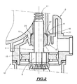
- Figure 2 is a partial longitudinal sectional view on a scale enlarged with respect to FIG. 1 of an embodiment of the gearmotor according to the invention.
- the geared motor 1 illustrated in FIG. 1 is intended for functional equipment of motor vehicles such as window regulators or opening roofs.
- stator 2 housed in a housing 3, a rotor 4 placed at the interior of the stator 2, provided with an armature shaft 5 carrying a manifold 6 and passing through a rolling bearing 7 housed in a support 8 of a casing reduction gear 9 in which the shaft 5 is arranged.
- the manifold 6 cooperates with brushes 15.
- the shaft 5 has, internally to the housing 9, a worm 11 cooperating with a toothed wheel not shown also housed in the gearbox 9.
- the latter contains a lubricant (grease, oil) for the gear constituted by the worm 11 and the toothed wheel.
- a lubricant grey, oil
- the armature shaft 5 and the rotor 4 have a longitudinal axis XX oriented vertically when the gearmotor is thus arranged, in vehicle windows or other equipment functional.
- the rolling bearing 7 has at its opposite ends spherical surfaces 12, 13 connected by a cylindrical surface central 14, these different surfaces being supported on spans of profiles complementary to the bearing support 8.
- a seal 17 is interposed between the rolling bearing 7 and the bearing support 18, and this on the side of the bearing 7 close to the interior of the housing 9.
- a housing ring 19 In the wall of the bearing support 18 is arranged a housing ring 19 whose profile is suitable for sealingly receiving the seal 17, which is placed in abutment on the corresponding spherical surface 12 of the bearing 7.
- the seal 17 can be O-ring as shown, or of different profile, for example lip.
- the wall of the housing 19 has two surfaces 21, 22 substantially perpendicular and connected by a rounded central span 23 supporting the seal 17.
- the bearing 23 constituting the bottom of the housing 19 has a spherical profile complementary to that of the seal 17.
- the latter has a Shore A hardness suitable for swiveling of the armature shaft 5, that is to say preferably from 30 to 50.
- the seal 17 and the housing 19 can be replaced by a seal and a housing of different profiles, complementary to each other.
Landscapes
- Engineering & Computer Science (AREA)
- General Engineering & Computer Science (AREA)
- Mechanical Engineering (AREA)
- Connection Of Motors, Electrical Generators, Mechanical Devices, And The Like (AREA)
- Motor Or Generator Frames (AREA)
- Rolling Contact Bearings (AREA)
- Sealing Of Bearings (AREA)
- General Details Of Gearings (AREA)
- Gear Transmission (AREA)
Abstract
Description
Claims (4)
- Motoréducteur (16) destiné à des équipements fonctionnels de véhicules automobiles tels que lève-vitre, toits ouvrants ou sièges, comprenant un rotor (4) pourvu d'un arbre d'induit (5) portant un collecteur (6) et traversant un palier de roulement (7) logé dans un support (18) d'un carter réducteur (9) dans lequel est disposé ledit arbre, une vis sans fin (11) de l'arbre coopérant avec une roue dentée logée dans le carter réducteur, caractérisé en ce qu'un joint d'étanchéité (17) est interposé entre le palier et le support de palier, du côté du palier proche de l'intérieur du carter réducteur, et disposé en appui sur une surface sphérique (12) du palier (7) de roulement.
- Motoréducteur selon la revendication 1, caractérisé en ce que dans la paroi du support (18) de palier est agencé un logement annulaire (19) dont le profil est adapté pour recevoir de manière étanche le joint (17).
- Motoréducteur selon la revendication 2, caractérisé en ce que le joint d'étanchéité (17) est torique et la paroi du logement (19) présente deux surfaces sensiblement perpendiculaires (21, 22) raccordées par une portée centrale arrondie (23) d'appui du joint.
- Motoréducteur selon l'une quelconque des revendications 1 à 3, caractérisé en ce que le joint (17) est en contact uniquement avec le support (18) et la surface sphérique (12) du palier (7).
Applications Claiming Priority (2)
| Application Number | Priority Date | Filing Date | Title |
|---|---|---|---|
| FR0000292 | 2000-01-11 | ||
| FR0000292A FR2803699B1 (fr) | 2000-01-11 | 2000-01-11 | Motoreducteur destine a des equipements fonctionnels de vehicules automobiles |
Publications (2)
| Publication Number | Publication Date |
|---|---|
| EP1117170A1 true EP1117170A1 (fr) | 2001-07-18 |
| EP1117170B1 EP1117170B1 (fr) | 2003-10-15 |
Family
ID=8845785
Family Applications (1)
| Application Number | Title | Priority Date | Filing Date |
|---|---|---|---|
| EP01400058A Expired - Lifetime EP1117170B1 (fr) | 2000-01-11 | 2001-01-10 | Motoréducteur destiné à des équipements fonctionnels de véhicules automobiles |
Country Status (7)
| Country | Link |
|---|---|
| US (1) | US6658956B2 (fr) |
| EP (1) | EP1117170B1 (fr) |
| JP (1) | JP2001238394A (fr) |
| BR (1) | BR0100047A (fr) |
| DE (1) | DE60100954T2 (fr) |
| ES (1) | ES2208524T3 (fr) |
| FR (1) | FR2803699B1 (fr) |
Families Citing this family (2)
| Publication number | Priority date | Publication date | Assignee | Title |
|---|---|---|---|---|
| US6820822B2 (en) | 2002-07-29 | 2004-11-23 | Jeffrey Daniels | No leak seal system for irrigation wheel-drive gearbox |
| EP1626481B1 (fr) * | 2003-05-19 | 2011-08-17 | Asmo Co., Ltd. | Procede de production d'un arbre d'induit, arbre d'induit, et machine electrique tournante |
Citations (3)
| Publication number | Priority date | Publication date | Assignee | Title |
|---|---|---|---|---|
| FR2196540A1 (fr) * | 1972-08-16 | 1974-03-15 | Nippon Denso Co | |
| DE8903714U1 (de) * | 1989-03-23 | 1990-01-25 | Siemens AG, 1000 Berlin und 8000 München | Verstellantrieb, insbesondere Kraftfahrzeug-Fensterheberantrieb |
| EP0509263A2 (fr) * | 1991-04-18 | 1992-10-21 | Siemens Aktiengesellschaft | Entraînement par moto-réducteur pour véhicules automobiles |
Family Cites Families (8)
| Publication number | Priority date | Publication date | Assignee | Title |
|---|---|---|---|---|
| GB1004103A (en) * | 1960-12-19 | 1965-09-08 | Licentia Gmbh | A sintered bearing bush |
| US3506315A (en) * | 1967-06-13 | 1970-04-14 | Roy W Young Jr | Self-aligning bearing and process for its fabrication |
| DE2244275C3 (de) * | 1972-09-09 | 1975-09-04 | Frankl & Kirchner, Fabrik Fuer Elektromotoren U. Elektrische Apparate, 6830 Schwetzingen | Gekapselter Kollektormotor für ein Pumpenaggregat |
| US4060287A (en) * | 1976-06-30 | 1977-11-29 | Kamatics Corporation | Bearing seal and method of forming same |
| US4519614A (en) * | 1984-04-09 | 1985-05-28 | Rock Bit Industries U.S.A., Inc. | Generally cylindrical rotary drill face seal having improved resistance to radial distortion |
| US4619588A (en) * | 1984-04-25 | 1986-10-28 | Facet Enterprises, Incorporated | Wet motor gerotor fuel pump with vapor vent valve and improved flow through the armature |
| US5414316A (en) * | 1991-04-18 | 1995-05-09 | Siemens Aktiengesellschaft | Motor vehicle gear motor drive |
| US5470158A (en) * | 1994-12-29 | 1995-11-28 | The Torrington Company | Seal for rolling bearings |
-
2000
- 2000-01-11 FR FR0000292A patent/FR2803699B1/fr not_active Expired - Fee Related
-
2001
- 2001-01-10 JP JP2001002825A patent/JP2001238394A/ja not_active Withdrawn
- 2001-01-10 DE DE60100954T patent/DE60100954T2/de not_active Expired - Fee Related
- 2001-01-10 BR BR0100047-0A patent/BR0100047A/pt active Search and Examination
- 2001-01-10 ES ES01400058T patent/ES2208524T3/es not_active Expired - Lifetime
- 2001-01-10 EP EP01400058A patent/EP1117170B1/fr not_active Expired - Lifetime
- 2001-01-11 US US09/758,907 patent/US6658956B2/en not_active Expired - Fee Related
Patent Citations (3)
| Publication number | Priority date | Publication date | Assignee | Title |
|---|---|---|---|---|
| FR2196540A1 (fr) * | 1972-08-16 | 1974-03-15 | Nippon Denso Co | |
| DE8903714U1 (de) * | 1989-03-23 | 1990-01-25 | Siemens AG, 1000 Berlin und 8000 München | Verstellantrieb, insbesondere Kraftfahrzeug-Fensterheberantrieb |
| EP0509263A2 (fr) * | 1991-04-18 | 1992-10-21 | Siemens Aktiengesellschaft | Entraînement par moto-réducteur pour véhicules automobiles |
Also Published As
| Publication number | Publication date |
|---|---|
| DE60100954T2 (de) | 2004-09-09 |
| JP2001238394A (ja) | 2001-08-31 |
| DE60100954D1 (de) | 2003-11-20 |
| FR2803699A1 (fr) | 2001-07-13 |
| FR2803699B1 (fr) | 2006-11-03 |
| EP1117170B1 (fr) | 2003-10-15 |
| US20010009114A1 (en) | 2001-07-26 |
| ES2208524T3 (es) | 2004-06-16 |
| BR0100047A (pt) | 2001-08-21 |
| US6658956B2 (en) | 2003-12-09 |
Similar Documents
| Publication | Publication Date | Title |
|---|---|---|
| FR2612991A1 (fr) | Dispositif de support d'un arbre coulissant de demarreur | |
| EP0631072A1 (fr) | Joint d'étanchéité pour arbre tournant | |
| FR2574034A1 (fr) | Palier de guidage lineaire etanche pour systeme d'essuie-glace a mouvement alternatif | |
| EP1117170B1 (fr) | Motoréducteur destiné à des équipements fonctionnels de véhicules automobiles | |
| FR2722463A1 (fr) | Dispositif de lave-glace, notamment pour vehicule automobile | |
| FR2953567A1 (fr) | Pompe a piston muni d'un dispositif d'etancheite | |
| FR2544442A1 (fr) | Joint a fluide, notamment a lubrifiant | |
| FR2594752A1 (fr) | Dispositif pour le montage d'une roue motrice de vehicule automobile | |
| EP0467750B1 (fr) | Dispositif de montage d'un arbre d'entraînement, notamment pour essuie-glace | |
| FR2604226A1 (fr) | Dispositif pour rendre etanches des paliers d'arbre ou des carters de palier d'arbre. | |
| FR2731482A1 (fr) | Agencement de montage pour la roue d'entrainement et le rotor d'une pompe a eau de refroidissement pour vehicules automobiles | |
| FR2803954A1 (fr) | Motoreducteur destine a des equipements fonctionnels de vehicules, pourvu d'une bague magnetique de mesure de la vitesse de rotation de son arbre d'induit | |
| EP0296960A1 (fr) | Roulement axial, notamment pour suspensions à amortisseur de véhicules automobiles | |
| FR2748436A1 (fr) | Motoreducteur pour essuie-glace sans butee de blocage d'arbre | |
| FR2828921A1 (fr) | Dispositif d'etancheite entre deux elements de machine, notamment entre un carter et un arbre | |
| FR2764030A1 (fr) | Dispositif d'actionnement d'une boite a vitesses automatisee | |
| FR2923784A1 (fr) | Dispositif d'essuie-glace | |
| EP0505255B1 (fr) | Dispositif de lave-glace, notamment pour surface vitrée de véhicule automobile | |
| EP0192615A2 (fr) | Dispositif d'étanchéité radiale en acier pour groupes de roulement | |
| FR3037020A1 (fr) | Ensemble d'entrainement a arbre rotatif pour un ensemble d'essuyage de vitre de vehicule automobile | |
| FR2885393A1 (fr) | Demarreur de moteur concu pour presenter une durabilite amelioree | |
| FR2642809A1 (fr) | Dispositif d'etancheite notamment pour vehicules automobiles comportant au moins une piece profilee tubulaire | |
| KR20100023900A (ko) | 와이퍼 구동기 | |
| FR2510687A1 (fr) | Roulement de portee radiale et de butee bilaterale, destine notamment a une poulie debrayable d'entrainement d'un dispositif auxiliaire de vehicule automobile | |
| FR2912788A1 (fr) | Dispositif etanche de transmission d'un mouvement de rotation a l'interieur d'une chambre |
Legal Events
| Date | Code | Title | Description |
|---|---|---|---|
| PUAI | Public reference made under article 153(3) epc to a published international application that has entered the european phase |
Free format text: ORIGINAL CODE: 0009012 |
|
| AK | Designated contracting states |
Kind code of ref document: A1 Designated state(s): DE ES GB IT |
|
| AX | Request for extension of the european patent |
Free format text: AL;LT;LV;MK;RO;SI |
|
| RTI1 | Title (correction) |
Free format text: GEARED MOTOR DRIVE FOR FUNCTIONNAL VEHICLE EQUIPMENT |
|
| 17P | Request for examination filed |
Effective date: 20011224 |
|
| AKX | Designation fees paid |
Free format text: DE ES GB IT |
|
| 17Q | First examination report despatched |
Effective date: 20020521 |
|
| GRAH | Despatch of communication of intention to grant a patent |
Free format text: ORIGINAL CODE: EPIDOS IGRA |
|
| RAP1 | Party data changed (applicant data changed or rights of an application transferred) |
Owner name: ARVINMERITOR LIGHT VEHICLE SYSTEMS-FRANCE |
|
| GRAS | Grant fee paid |
Free format text: ORIGINAL CODE: EPIDOSNIGR3 |
|
| GRAA | (expected) grant |
Free format text: ORIGINAL CODE: 0009210 |
|
| AK | Designated contracting states |
Kind code of ref document: B1 Designated state(s): DE ES GB IT |
|
| REG | Reference to a national code |
Ref country code: GB Ref legal event code: FG4D |
|
| REG | Reference to a national code |
Ref country code: GB Ref legal event code: FG4C Free format text: NOTIFICATION RECEIVED FROM THE EUROPEAN PATENT OFFICE THAT THE PUBLICATION LANGUAGE IS ACTUALLY FRENCH. |
|
| REF | Corresponds to: |
Ref document number: 60100954 Country of ref document: DE Date of ref document: 20031120 Kind code of ref document: P |
|
| GBT | Gb: translation of ep patent filed (gb section 77(6)(a)/1977) |
Effective date: 20040107 |
|
| REG | Reference to a national code |
Ref country code: ES Ref legal event code: FG2A Ref document number: 2208524 Country of ref document: ES Kind code of ref document: T3 |
|
| PGFP | Annual fee paid to national office [announced via postgrant information from national office to epo] |
Ref country code: ES Payment date: 20040708 Year of fee payment: 4 |
|
| PLBE | No opposition filed within time limit |
Free format text: ORIGINAL CODE: 0009261 |
|
| STAA | Information on the status of an ep patent application or granted ep patent |
Free format text: STATUS: NO OPPOSITION FILED WITHIN TIME LIMIT |
|
| 26N | No opposition filed |
Effective date: 20040716 |
|
| PGFP | Annual fee paid to national office [announced via postgrant information from national office to epo] |
Ref country code: GB Payment date: 20050105 Year of fee payment: 5 |
|
| PG25 | Lapsed in a contracting state [announced via postgrant information from national office to epo] |
Ref country code: ES Free format text: LAPSE BECAUSE OF NON-PAYMENT OF DUE FEES Effective date: 20050111 |
|
| PG25 | Lapsed in a contracting state [announced via postgrant information from national office to epo] |
Ref country code: GB Free format text: LAPSE BECAUSE OF NON-PAYMENT OF DUE FEES Effective date: 20060110 |
|
| PGFP | Annual fee paid to national office [announced via postgrant information from national office to epo] |
Ref country code: IT Payment date: 20060131 Year of fee payment: 6 |
|
| PGFP | Annual fee paid to national office [announced via postgrant information from national office to epo] |
Ref country code: DE Payment date: 20060228 Year of fee payment: 6 |
|
| REG | Reference to a national code |
Ref country code: ES Ref legal event code: FD2A Effective date: 20050111 |
|
| GBPC | Gb: european patent ceased through non-payment of renewal fee |
Effective date: 20060110 |
|
| PG25 | Lapsed in a contracting state [announced via postgrant information from national office to epo] |
Ref country code: DE Free format text: LAPSE BECAUSE OF NON-PAYMENT OF DUE FEES Effective date: 20070801 |
|
| PG25 | Lapsed in a contracting state [announced via postgrant information from national office to epo] |
Ref country code: IT Free format text: LAPSE BECAUSE OF NON-PAYMENT OF DUE FEES Effective date: 20070110 |