EP1117153A2 - Protecting configuration for flat cables - Google Patents
Protecting configuration for flat cables Download PDFInfo
- Publication number
- EP1117153A2 EP1117153A2 EP00310470A EP00310470A EP1117153A2 EP 1117153 A2 EP1117153 A2 EP 1117153A2 EP 00310470 A EP00310470 A EP 00310470A EP 00310470 A EP00310470 A EP 00310470A EP 1117153 A2 EP1117153 A2 EP 1117153A2
- Authority
- EP
- European Patent Office
- Prior art keywords
- enclosure
- members
- cables
- flat cables
- flat
- Prior art date
- Legal status (The legal status is an assumption and is not a legal conclusion. Google has not performed a legal analysis and makes no representation as to the accuracy of the status listed.)
- Granted
Links
Images


Classifications
-
- H—ELECTRICITY
- H01—ELECTRIC ELEMENTS
- H01R—ELECTRICALLY-CONDUCTIVE CONNECTIONS; STRUCTURAL ASSOCIATIONS OF A PLURALITY OF MUTUALLY-INSULATED ELECTRICAL CONNECTING ELEMENTS; COUPLING DEVICES; CURRENT COLLECTORS
- H01R12/00—Structural associations of a plurality of mutually-insulated electrical connecting elements, specially adapted for printed circuits, e.g. printed circuit boards [PCB], flat or ribbon cables, or like generally planar structures, e.g. terminal strips, terminal blocks; Coupling devices specially adapted for printed circuits, flat or ribbon cables, or like generally planar structures; Terminals specially adapted for contact with, or insertion into, printed circuits, flat or ribbon cables, or like generally planar structures
- H01R12/50—Fixed connections
- H01R12/59—Fixed connections for flexible printed circuits, flat or ribbon cables or like structures
- H01R12/61—Fixed connections for flexible printed circuits, flat or ribbon cables or like structures connecting to flexible printed circuits, flat or ribbon cables or like structures
-
- H—ELECTRICITY
- H01—ELECTRIC ELEMENTS
- H01R—ELECTRICALLY-CONDUCTIVE CONNECTIONS; STRUCTURAL ASSOCIATIONS OF A PLURALITY OF MUTUALLY-INSULATED ELECTRICAL CONNECTING ELEMENTS; COUPLING DEVICES; CURRENT COLLECTORS
- H01R12/00—Structural associations of a plurality of mutually-insulated electrical connecting elements, specially adapted for printed circuits, e.g. printed circuit boards [PCB], flat or ribbon cables, or like generally planar structures, e.g. terminal strips, terminal blocks; Coupling devices specially adapted for printed circuits, flat or ribbon cables, or like generally planar structures; Terminals specially adapted for contact with, or insertion into, printed circuits, flat or ribbon cables, or like generally planar structures
- H01R12/50—Fixed connections
- H01R12/59—Fixed connections for flexible printed circuits, flat or ribbon cables or like structures
- H01R12/65—Fixed connections for flexible printed circuits, flat or ribbon cables or like structures characterised by the terminal
- H01R12/69—Fixed connections for flexible printed circuits, flat or ribbon cables or like structures characterised by the terminal deformable terminals, e.g. crimping terminals
-
- H—ELECTRICITY
- H01—ELECTRIC ELEMENTS
- H01R—ELECTRICALLY-CONDUCTIVE CONNECTIONS; STRUCTURAL ASSOCIATIONS OF A PLURALITY OF MUTUALLY-INSULATED ELECTRICAL CONNECTING ELEMENTS; COUPLING DEVICES; CURRENT COLLECTORS
- H01R12/00—Structural associations of a plurality of mutually-insulated electrical connecting elements, specially adapted for printed circuits, e.g. printed circuit boards [PCB], flat or ribbon cables, or like generally planar structures, e.g. terminal strips, terminal blocks; Coupling devices specially adapted for printed circuits, flat or ribbon cables, or like generally planar structures; Terminals specially adapted for contact with, or insertion into, printed circuits, flat or ribbon cables, or like generally planar structures
- H01R12/70—Coupling devices
- H01R12/77—Coupling devices for flexible printed circuits, flat or ribbon cables or like structures
- H01R12/771—Details
- H01R12/772—Strain relieving means
-
- H—ELECTRICITY
- H01—ELECTRIC ELEMENTS
- H01R—ELECTRICALLY-CONDUCTIVE CONNECTIONS; STRUCTURAL ASSOCIATIONS OF A PLURALITY OF MUTUALLY-INSULATED ELECTRICAL CONNECTING ELEMENTS; COUPLING DEVICES; CURRENT COLLECTORS
- H01R13/00—Details of coupling devices of the kinds covered by groups H01R12/70 or H01R24/00 - H01R33/00
- H01R13/46—Bases; Cases
- H01R13/502—Bases; Cases composed of different pieces
- H01R13/506—Bases; Cases composed of different pieces assembled by snap action of the parts
Definitions
- the present invention relates to a protecting configuration for flat electrical cables.
- One example of a conventional FPC flat cable consists of a conductive path formed on an insulating base film, an upper face thereof being covered by a protective film.
- An example using this type of configuration, wherein conductive paths between a plurality of flat cables are connected, is described in JP 4-359874.
- a portion of a film face of a pair of cables is cut away to expose the conductive path within and, with the two flat cables in a state whereby one is above the other, a connecting terminal is used to crimp the exposed portions of the two conductive paths together, thereby connecting the conductive paths via this connecting terminal.
- the present invention has taken the above problem into consideration, and aims to present a configuration for protecting connecting portions between a plurality of flat cables.
- an enclosure for protecting an electrical connection between overlying flat electrical cables each having of a non-conductive flexible carrier strip and a conductive path, said enclosure being adapted to surround said electrical connection and to grip said cables.
- Such an enclosure both protects the electrical connection, for example a clamp-type terminal, and grips the cables so as to prevent stretching or twisting forces being transmitted to the connection.
- protrusions of the enclosure pass through preformed apertures of the cable so as to fix the relative position of cable and connector and to ensure effective transmission of forces from one side of the connection to the other.
- the enclosure is preferably formed from identical half-members, and has a releasable latch to hold the half-members together.
- the latch is preferably a snap fit.
- the enclosure preferably seals against the flexible carrier strip between adjacent conductive paths so as to provide an insulating and moisture barrier.
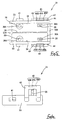
- Figure 1 is a diagonal view showing a protecting configuration for a flat cable of the present embodiment in a state prior to being joined.
- Figure 2 is a cross-sectional view showing the flat cable.
- Figure 3 is a diagonal view showing a connecting terminal.
- Figure 4 is a cross-sectional view showing the flat cables being connected by the connecting terminals.
- figure 5 is a plan view of a half-member.
- Figure 6 is a side face view of the half-member.
- Figure 7 is a cross-sectional view showing the protecting configuration for a flat cable in a state prior to being joined.
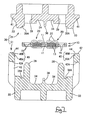
- Figure 8 is a cross-sectional view showing the protecting configuration for a flat cable in a joined state.
- a configuration for protecting flat cables of the present embodiment consists of an upper and lower pair of flat cables 10, a pair of connecting terminals 20 that are crimped to the two flat cables 10, and a protecting member 30 formed from a pair of half-members 31 that are joined together and attached to the two flat cables 10.
- the flat cables 10 consist of a conductive path, composed of a metal film such as copper foil, printed in a specified circuit pattern on the surface of a plastic base film, the exposed surface thereof then being covered with a protective film.
- Each of the two flat cables 10 is provided with a pair of conductive paths 13 provided longitudinally within ribbon-shaped film 11, the two flat cables 20 being provided one above the other.
- each of the two flat cables has a pair of cut-away portions 14 that have been cut away in a rectangular shape from an outer face side of the film 11.
- the conductive paths 13 at the interior of the flat cables 10 are exposed from these cut-away portions 14. Connecting terminals 20 (to be explained) are crimped to these exposed portions.
- four circular position fixing holes 15 pass through the film 11 around the periphery of the cut-away portions 14. These position fixing holes 15 are provided so as to have the cut-away portions 14 located therebetween in the length-wise and width-wise directions of the flat cables 10.
- Each connecting terminal 20 is formed from conductive metal. As shown in Figure 3, it has a rectangular base member 21 provided with a protrusion 21 A on its upper face, and claws 22 that have tapering tips. One side edge of the base member 21 has one claw 22 protruding therefrom, the other side has two claws 22 protruding therefrom.
- the conductive path 13 of each cut-away portion 14 is positioned between the left and right claws 22 which are then made to pierce the film 11 from below.
- the tips of the claws 22 are then bent inwards so that they crimp the conductive path 13 within each cut-away portion 14 from above and below (see Figure 4).
- the tips of the claws 22 make contact with the upper conductive paths 13, and the protrusions 21A make contact with the lower conductive paths 13, thereby electrically connecting the upper and lower conductive paths 13 via these connecting terminals 20.
- the protecting member 30 is formed from the pair of identically shaped half-members 31 that are joined together (see Figure 1 and Figures 5 to 7).
- the half-members 31 are made from plastic and form a box shape.
- the side that is attached to the flat cable 10 is designated the upper side (see the lower half-member 31 in Figure 1)
- the width-wise direction of the flat cable 10 is designated the left-right direction
- the length-wise direction of the flat cable 10 is designated the anterior-posterior direction. (The closer side in Figure 1 is designated the anterior side.)
- Each half-member 31 is provided with an anterior face wall 32A, a posterior face wall 32B, and left and right side walls 33. Upper edges of the left and right side walls 33 protrude slightly above an upper face of the half-member 31, and one of the two flat cables 10 can be fitted therebetween in an anterior-posterior direction.
- a pair of left and right grooves 34 are formed in the upper face of the half-member 31, these being divided by a dividing wall 36 that extends in the anterior-posterior direction.
- a pin-shaped position fixing protrusion 38 protrudes upwards from a posterior portion of each groove 14, a base end of each position fixing protrusion 38 forming a pressing member 38A that has a flat upper face.
- the position fixing protrusions 38 are located in positions corresponding to the position fixing holes 15 of the flat cable 10, and can be fitted tightly therein.
- Pin receiving holes 39 open into anterior portions of the grooves 34, the position fixing protrusions 38 of the corresponding half-member 31 being fitted therein.
- the circumference of the pin receiving holes 39 form pressing members 39A that are provided with flat upper faces.
- the upper faces of the pressing members 38A and 39A, the upper edge faces of the anterior face wall 32A and posterior face wall 32B, and an upper edge face of the dividing wall 36 are all the same height. Consequently, as will be explained later, the pair of flat cables 10 can be clamped between these components and the components of the corresponding half-member 31.
- a pair of locking protrusions 41 protrude sideways from faces of the left and right side walls 33 at the anterior of the half-member 31. These locking protrusions 41 are cross-sectionally wedge-shaped.
- a pair of locking members 42 protrude downwards from faces of the left and right side walls 33 at the posterior of the half-member 31. These locking members 42 are U-shaped and are capable of bending outwards.
- a locking hole 42A opens into the centre of each locking member 42, a corresponding locking protrusion 41 being inserted tightly therein in an anterior-posterior direction, and the two mutually engaging.
- An anterior and posterior pair of tapered faces 44 are formed on tips of the locking members 42, these tapered faces 44 being inclined inwards.
- a guiding groove 45 is provided in a stepped shape between the anterior and posterior pair of tapered faces 44.
- This guiding groove 45 is provided with an inwardly inclined tapered face 45A.
- the dimensions of these guiding grooves 45, between their anterior and posterior ends 45B, is slightly greater than the width of the locking protrusions 41.
- the locking protrusions 41 are inserted into the guiding grooves 45, thereby fixing the position of the two half-members 31 in an anterior-posterior direction at a location where the locking protrusions 41 and the locking members 42 fit together.
- the present embodiment is configured as described above. Next, the operation thereof is described.
- the position fixing protrusions 38 of the first half-member 31 are first inserted into the corresponding position fixing holes 15, and the flat cable 10 is brought to rest over the upper face of the half-member 31 )shown by the two-dot chain line in Figure 1).
- the second half-member 31 is brought close to the first half-member 31 in a manner whereby the second half-member is laterally reversed relative to the first. Then the tapered faces 44 of the tips of the locking members 42 guide the first half-member 31 between the two locking members 42 of the second half-member 31. The two half-members 31 are brought closer together, and the locking protrusions 41 of the second half-member 31 make contact with the tips of the locking members 42. Then the two half-members 31 are pressed against one another while being slid in an anterior-posterior direction, and the locking protrusions 41 enter the corresponding guiding grooves 45.
- the two half-members 31 reach a state whereby their position relative to one another is fixed in the anterior-posterior direction.
- the locking protrusions 41 are in a position whereby they can fit into the corresponding locking holes 42A
- the position fixing protrusions 38 are in a position whereby they can fit into the corresponding pin receiving holes 39. If the two half-members 31 are pressed against one another from this state, the locking protrusions 41 pass along the tapered faces 45A and enter the interior of the corresponding locking members 42. These locking members 42 bend outwards relative to one another, and the position fixing protrusions 38 enter the corresponding pin receiving holes 39.
- the locking members 42 return to their original position when the locking protrusions 41 reach the locking holes 42A, and the locking protrusions 41 engage with the locking members 42, thereby locking the two half-members 31 in a correct attaching state (see Figure 8). In this manner, the two half-members 31 that form the protecting member 30 are in an attached state with the flat cables 10.
- the conductive paths 13 that protrude from the connecting terminals 20 and the cut-away portions 14 are housed within the grooves 34 of the protecting member 30, and the periphery thereof is in a covered state.
- the protecting member 30 is attached to the pair of flat cables 10 in a manner whereby is clamps them. Consequently, the two flat cables 10 are maintained in their overlapping state.
- the position fixing protrusions 38 that are part of the position fixing means are inserted tightly within the position fixing holes 15, thereby fixing the position of the protecting member 30 and the two flat cables 10, relative to one another, in the anterior-posterior and left-right directions. Further, these position fixing means are located in positions whereby they clamp the connecting terminals 20 therebetween relative to the length-wise and width-wise direction of the flat cables 10. If the flat cables 10 are pulled or twisted, for example, this force will be received directly by connecting portions of the flat cables 10, the there is the danger that the connecting terminals 20 may bend and the connection may deteriorate. However, the position fixing means 38 and 15 described above are positioned so as to clamp the connecting terminals 20 in the length-wise direction of the flat cables 10.
- any force (particularly a pulling force) transmitted from any part of the flat cables 10 to the connecting portions is reduced.
- the position fixing means 38 and 15 are positioned so as to clamp the connecting terminals 20 in the width-wise direction of the flat cables 10 as well. Consequently, any force transmitted to the connecting portions from the flat cables 10 (particularly, any force resulting from twisting the flat cables 10) is reduced
- the pair of connecting terminals 20 are separated by the dividing wall 36 that is closely attached to the face of the film 11. Consequently, if water or the like should enter the interior of the protecting member 30, this water can be prevented from leaking from one connecting terminal 20 to the other.
- the protecting member 30 is formed from the half-members 31 that are identical in shape. Consequently, only one type of component needs to be produced, and costs can be reduced.
- the locking protrusions 41 and the locking members 42 are formed on the two half-members 31, and the guiding grooves 45, into which the locking protrusions 41 are inserted, are formed in the tips of the locking members 42.
- the locking protrusions 41 make contact with the tips of the locking members 42, and sliding the two half-members 31 in the anterior-posterior direction causes the locking protrusions 41 to enter the guiding grooves 45.
- the position (in the anterior-posterior direction) of the two half-members 31 is fixed by the fitting of the locking protrusions 41 and the locking holes 42A.
- the fitting operation of the locking protrusions 41 and the locking holes 42A is simple, and the joining operation can be performed smoothly.
- the flat cable may comprise a conductive strip within a somewhat thin tubular bag of insulating material.
Landscapes
- Multi-Conductor Connections (AREA)
- Coupling Device And Connection With Printed Circuit (AREA)
Abstract
Description
Claims (10)
- An enclosure (30) for protecting an electrical connection between overlying flat electrical cables (10) each having of a non-conductive flexible carrier strip (11) and a conductive path (13), said enclosure (30) being adapted to surround said electrical connection and to grip said cables (10).
- An enclosure (30) according to claim 1 and having an electrical terminal (20) connecting said cables, said enclosure (30) fixing said terminal (20) in the lengthwise direction of said cables (10).
- An enclosure according to claim 1 or claim 2 and defining two longitudinal pathways (34), one pathway for each of two conductive paths (13) of a flat electrical cable (10), and each pathway (34) being separated by a dividing wall (36) adapted to tightly engage a flexible carrier strip (11) between said conductive paths (13).
- An enclosure according to any preceding claim and comprising a pair of identical half-members (31) adapted to engage a flat electrical cable (10) on the flat surface thereof and having a latch (41,42) to retain the half-members (31) together.
- An enclosure according to claim 4 wherein said latch comprises a protruding latch member (41) of one of said half members, and a recess (42A) of the other of said half members engageable with said latch member (41).
- An enclosure according to claim 5 wherein said recess (42A) is defined by a resilient 'U' shaped projection (42) of said other half member.
- An enclosure according to claim 6 wherein the outermost portion of said projection (42) defines a groove (45A) adapted to receive and guide said latch member (41) to said recess (42A).
- An enclosure according to any preceding claim and having position fixing protrusions (38) engageable through said flexible carrier strip (11).
- An enclosure according to claim 8 wherein the free ends of said protrusions (38) are engageable in corresponding recesses (39) of said enclosure.
- An enclosure according to claim 9 wherein said protrusions (38) and recesses (39) define abutment surfaces (38A, 39A) adapted to grip said cables (10) in use.
Applications Claiming Priority (2)
| Application Number | Priority Date | Filing Date | Title |
|---|---|---|---|
| JP2000002636 | 2000-01-11 | ||
| JP2000002636A JP2001196115A (en) | 2000-01-11 | 2000-01-11 | Protecting structure of flat cable |
Publications (3)
| Publication Number | Publication Date |
|---|---|
| EP1117153A2 true EP1117153A2 (en) | 2001-07-18 |
| EP1117153A3 EP1117153A3 (en) | 2002-08-07 |
| EP1117153B1 EP1117153B1 (en) | 2008-03-26 |
Family
ID=18531720
Family Applications (1)
| Application Number | Title | Priority Date | Filing Date |
|---|---|---|---|
| EP00310470A Expired - Lifetime EP1117153B1 (en) | 2000-01-11 | 2000-11-24 | Protecting configuration for flat cables |
Country Status (4)
| Country | Link |
|---|---|
| US (1) | US6483035B2 (en) |
| EP (1) | EP1117153B1 (en) |
| JP (1) | JP2001196115A (en) |
| DE (1) | DE60038434T2 (en) |
Cited By (2)
| Publication number | Priority date | Publication date | Assignee | Title |
|---|---|---|---|---|
| WO2006103204A1 (en) * | 2005-03-30 | 2006-10-05 | Helianthos, B.V. | Connector housing assembly and method for housing a connector contact connecting a wire to a conducting lead in a piece of foil |
| WO2012136862A1 (en) * | 2011-04-04 | 2012-10-11 | Universidad De Huelva | Self-inserting male rj connector |
Families Citing this family (9)
| Publication number | Priority date | Publication date | Assignee | Title |
|---|---|---|---|---|
| WO2008100246A2 (en) * | 2007-02-09 | 2008-08-21 | Bell Helicopter Textron Inc. | Self-retaining anti-rotation clip |
| US8960973B1 (en) * | 2011-10-06 | 2015-02-24 | Cooper Technologies Company | Splice enclosure for luminaires |
| KR101601506B1 (en) * | 2014-10-17 | 2016-03-09 | 현대자동차주식회사 | Cable combination device |
| DE102015208400B4 (en) * | 2015-05-06 | 2024-02-22 | Eaton Intelligent Power Limited | Cable/wire entry |
| JP6579226B1 (en) * | 2018-05-25 | 2019-09-25 | 株式会社オートネットワーク技術研究所 | Wiring member |
| JP7042404B2 (en) * | 2019-03-05 | 2022-03-28 | 株式会社オートネットワーク技術研究所 | Wire harness module and wire harness routing device |
| JP7042405B2 (en) * | 2019-03-05 | 2022-03-28 | 株式会社オートネットワーク技術研究所 | Wire harness unit and wire harness mounting structure |
| US11489288B2 (en) | 2020-08-28 | 2022-11-01 | Raytheon Company | Connector retention clip |
| US11728636B2 (en) * | 2021-12-31 | 2023-08-15 | Lear Corporation | Flat flexible electrical conductor and supporting device therefor |
Family Cites Families (16)
| Publication number | Priority date | Publication date | Assignee | Title |
|---|---|---|---|---|
| US3960430A (en) * | 1974-10-29 | 1976-06-01 | Amp Incorporated | Flat wiring system and crimped connection |
| US4192965A (en) * | 1977-12-29 | 1980-03-11 | Gte Automatic Electric Laboratories Incorporated | Flat ribbon cable retainer |
| US4833775A (en) * | 1981-10-26 | 1989-05-30 | Burndy Corporation | Electrical connection apparatus for flat conductor cables and similar articles |
| JPS5957866U (en) * | 1982-10-08 | 1984-04-16 | 松下電工株式会社 | Structure of flat cable connection |
| US4508399A (en) * | 1984-01-03 | 1985-04-02 | Amp Incorporated | Polarized ribbon cable connector having circuit components therein |
| JPH0754720B2 (en) | 1987-04-10 | 1995-06-07 | Electrical connection terminals for flexible printed circuit boards | |
| US4975080A (en) * | 1988-05-13 | 1990-12-04 | Amp Incorporated | Locking means for electrical interconnecting structures |
| JPH0747810Y2 (en) | 1990-05-09 | 1995-11-01 | 住友電装株式会社 | Electrical connector for flexible flat conductor cable |
| FR2665803B1 (en) * | 1990-08-09 | 1993-06-18 | Labinal | BYPASS CONNECTOR. |
| JPH04359874A (en) | 1991-06-06 | 1992-12-14 | Sumitomo Wiring Syst Ltd | Interconnecting method for conductor of flexible flat type conductor-cable |
| US5498172A (en) * | 1993-07-30 | 1996-03-12 | Sunx Kabushiki Kaisha | Electrical connector for interconnecting parallel multiconductor cables |
| ES2094613T3 (en) * | 1993-09-28 | 1997-01-16 | Siemens Ag | BUS LINE CONNECTOR AND BUS LINE. |
| JP3378175B2 (en) * | 1997-07-08 | 2003-02-17 | 矢崎総業株式会社 | Conductor connection structure |
| US6135779A (en) | 1998-02-05 | 2000-10-24 | The Whitaker Corporation | Contact for a conductor on a foil |
| JP2992269B1 (en) * | 1998-06-08 | 1999-12-20 | 北川工業株式会社 | Noise current absorber |
| JP2000173828A (en) * | 1998-12-07 | 2000-06-23 | Tdk Corp | Split ferrite core to eliminate noise for flat cable, noise eliminating component, wire harness and electronic equipment |
-
2000
- 2000-01-11 JP JP2000002636A patent/JP2001196115A/en active Pending
- 2000-11-24 DE DE60038434T patent/DE60038434T2/en not_active Expired - Lifetime
- 2000-11-24 EP EP00310470A patent/EP1117153B1/en not_active Expired - Lifetime
- 2000-12-20 US US09/739,958 patent/US6483035B2/en not_active Expired - Fee Related
Cited By (5)
| Publication number | Priority date | Publication date | Assignee | Title |
|---|---|---|---|---|
| WO2006103204A1 (en) * | 2005-03-30 | 2006-10-05 | Helianthos, B.V. | Connector housing assembly and method for housing a connector contact connecting a wire to a conducting lead in a piece of foil |
| AU2006228598B2 (en) * | 2005-03-30 | 2009-12-10 | Helianthos B.V. | Connector housing assembly and method for housing a connector contact connecting a wire to a conducting lead in a piece of foil |
| US7762835B2 (en) | 2005-03-30 | 2010-07-27 | Helianthos B.V. | Electrical contact connecting to a conducting lead embedded in a piece of foil |
| WO2012136862A1 (en) * | 2011-04-04 | 2012-10-11 | Universidad De Huelva | Self-inserting male rj connector |
| ES2389790A1 (en) * | 2011-04-04 | 2012-10-31 | Universidad De Huelva | Self-inserting male rj connector |
Also Published As
| Publication number | Publication date |
|---|---|
| EP1117153A3 (en) | 2002-08-07 |
| US20020092666A1 (en) | 2002-07-18 |
| DE60038434T2 (en) | 2009-04-02 |
| JP2001196115A (en) | 2001-07-19 |
| EP1117153B1 (en) | 2008-03-26 |
| US6483035B2 (en) | 2002-11-19 |
| DE60038434D1 (en) | 2008-05-08 |
Similar Documents
| Publication | Publication Date | Title |
|---|---|---|
| US5415562A (en) | Pressure welding connector | |
| EP0944130B1 (en) | Crimp connection | |
| JP3775557B2 (en) | connector | |
| US5417583A (en) | Insulation-piercing connector | |
| US3881796A (en) | Terminal for flat conductor | |
| US6068505A (en) | Electrical contact for flexible flat cable | |
| US6551129B2 (en) | Ground connector | |
| EP1401059B1 (en) | Method of manufacturing wire harness | |
| US6372990B1 (en) | Terminal for a cable and method for mounting a terminal | |
| EP0795930B1 (en) | High contact force pin-receiving electrical contact | |
| WO2007127467A2 (en) | Insulation displacement terminal | |
| US7118409B2 (en) | Connector and cable retainer | |
| US20030008549A1 (en) | Holder | |
| EP1326306B1 (en) | Connecting member for flat circuit member and method of connecting the connecting member and the flat circuit member | |
| US6483035B2 (en) | Protecting configuration for flat cables | |
| EP0717461B1 (en) | IDC branch connector for large range of wire sizes | |
| US7244139B2 (en) | Electric connector and method for manufacturing the same | |
| US4373765A (en) | Plug connection for ribbon cables | |
| JPH059905B2 (en) | ||
| EP1012920B1 (en) | Cable connector | |
| US4540224A (en) | Grounding clip for use with shielded, jacketed flat cable | |
| JP3377418B2 (en) | Electrical connector for circuit board | |
| CN101841100B (en) | Electrical connector with caulking housing, and shielding cable bundle | |
| US5246381A (en) | Electrical terminal for modulator connector | |
| JP4533829B2 (en) | Connecting terminal |
Legal Events
| Date | Code | Title | Description |
|---|---|---|---|
| PUAI | Public reference made under article 153(3) epc to a published international application that has entered the european phase |
Free format text: ORIGINAL CODE: 0009012 |
|
| 17P | Request for examination filed |
Effective date: 20001215 |
|
| AK | Designated contracting states |
Kind code of ref document: A2 Designated state(s): AT BE CH CY DE DK ES FI FR GB GR IE IT LI LU MC NL PT SE TR |
|
| AX | Request for extension of the european patent |
Free format text: AL;LT;LV;MK;RO;SI |
|
| PUAL | Search report despatched |
Free format text: ORIGINAL CODE: 0009013 |
|
| AK | Designated contracting states |
Kind code of ref document: A3 Designated state(s): AT BE CH CY DE DK ES FI FR GB GR IE IT LI LU MC NL PT SE TR |
|
| AX | Request for extension of the european patent |
Free format text: AL;LT;LV;MK;RO;SI |
|
| RIC1 | Information provided on ipc code assigned before grant |
Free format text: 7H 01R 12/08 A, 7H 01R 13/506 B |
|
| AKX | Designation fees paid |
Designated state(s): DE FR GB IT |
|
| 17Q | First examination report despatched |
Effective date: 20060410 |
|
| GRAP | Despatch of communication of intention to grant a patent |
Free format text: ORIGINAL CODE: EPIDOSNIGR1 |
|
| GRAS | Grant fee paid |
Free format text: ORIGINAL CODE: EPIDOSNIGR3 |
|
| GRAA | (expected) grant |
Free format text: ORIGINAL CODE: 0009210 |
|
| AK | Designated contracting states |
Kind code of ref document: B1 Designated state(s): DE FR GB IT |
|
| REG | Reference to a national code |
Ref country code: GB Ref legal event code: FG4D |
|
| REF | Corresponds to: |
Ref document number: 60038434 Country of ref document: DE Date of ref document: 20080508 Kind code of ref document: P |
|
| ET | Fr: translation filed | ||
| PLBE | No opposition filed within time limit |
Free format text: ORIGINAL CODE: 0009261 |
|
| STAA | Information on the status of an ep patent application or granted ep patent |
Free format text: STATUS: NO OPPOSITION FILED WITHIN TIME LIMIT |
|
| 26N | No opposition filed |
Effective date: 20081230 |
|
| GBPC | Gb: european patent ceased through non-payment of renewal fee |
Effective date: 20081124 |
|
| PG25 | Lapsed in a contracting state [announced via postgrant information from national office to epo] |
Ref country code: IT Free format text: LAPSE BECAUSE OF FAILURE TO SUBMIT A TRANSLATION OF THE DESCRIPTION OR TO PAY THE FEE WITHIN THE PRESCRIBED TIME-LIMIT Effective date: 20080326 |
|
| PG25 | Lapsed in a contracting state [announced via postgrant information from national office to epo] |
Ref country code: GB Free format text: LAPSE BECAUSE OF NON-PAYMENT OF DUE FEES Effective date: 20081124 |
|
| PGFP | Annual fee paid to national office [announced via postgrant information from national office to epo] |
Ref country code: FR Payment date: 20121130 Year of fee payment: 13 Ref country code: DE Payment date: 20121121 Year of fee payment: 13 |
|
| REG | Reference to a national code |
Ref country code: DE Ref legal event code: R119 Ref document number: 60038434 Country of ref document: DE |
|
| REG | Reference to a national code |
Ref country code: FR Ref legal event code: ST Effective date: 20140731 |
|
| PG25 | Lapsed in a contracting state [announced via postgrant information from national office to epo] |
Ref country code: DE Free format text: LAPSE BECAUSE OF NON-PAYMENT OF DUE FEES Effective date: 20140603 |
|
| REG | Reference to a national code |
Ref country code: DE Ref legal event code: R079 Ref document number: 60038434 Country of ref document: DE Free format text: PREVIOUS MAIN CLASS: H01R0012080000 Ipc: H01R0012500000 |
|
| PG25 | Lapsed in a contracting state [announced via postgrant information from national office to epo] |
Ref country code: FR Free format text: LAPSE BECAUSE OF NON-PAYMENT OF DUE FEES Effective date: 20131202 |
|
| REG | Reference to a national code |
Ref country code: DE Ref legal event code: R079 Ref document number: 60038434 Country of ref document: DE Free format text: PREVIOUS MAIN CLASS: H01R0012080000 Ipc: H01R0012500000 Effective date: 20141030 Ref country code: DE Ref legal event code: R119 Ref document number: 60038434 Country of ref document: DE Effective date: 20140603 |