EP1117150A1 - Electrical terminal member - Google Patents
Electrical terminal member Download PDFInfo
- Publication number
- EP1117150A1 EP1117150A1 EP00311323A EP00311323A EP1117150A1 EP 1117150 A1 EP1117150 A1 EP 1117150A1 EP 00311323 A EP00311323 A EP 00311323A EP 00311323 A EP00311323 A EP 00311323A EP 1117150 A1 EP1117150 A1 EP 1117150A1
- Authority
- EP
- European Patent Office
- Prior art keywords
- terminal member
- symmetry
- longitudinal axis
- electrical
- insulation displacement
- Prior art date
- Legal status (The legal status is an assumption and is not a legal conclusion. Google has not performed a legal analysis and makes no representation as to the accuracy of the status listed.)
- Granted
Links
- 238000006073 displacement reaction Methods 0.000 claims abstract description 25
- 238000009413 insulation Methods 0.000 claims abstract description 25
- 239000004020 conductor Substances 0.000 description 24
- 230000000712 assembly Effects 0.000 description 3
- 238000000429 assembly Methods 0.000 description 3
- 230000015572 biosynthetic process Effects 0.000 description 1
- 230000008878 coupling Effects 0.000 description 1
- 238000010168 coupling process Methods 0.000 description 1
- 238000005859 coupling reaction Methods 0.000 description 1
- 238000003780 insertion Methods 0.000 description 1
- 230000037431 insertion Effects 0.000 description 1
- 238000000034 method Methods 0.000 description 1
- 238000012986 modification Methods 0.000 description 1
- 230000004048 modification Effects 0.000 description 1
- 230000035755 proliferation Effects 0.000 description 1
Images

Classifications
-
- H—ELECTRICITY
- H01—ELECTRIC ELEMENTS
- H01R—ELECTRICALLY-CONDUCTIVE CONNECTIONS; STRUCTURAL ASSOCIATIONS OF A PLURALITY OF MUTUALLY-INSULATED ELECTRICAL CONNECTING ELEMENTS; COUPLING DEVICES; CURRENT COLLECTORS
- H01R4/00—Electrically-conductive connections between two or more conductive members in direct contact, i.e. touching one another; Means for effecting or maintaining such contact; Electrically-conductive connections having two or more spaced connecting locations for conductors and using contact members penetrating insulation
- H01R4/24—Connections using contact members penetrating or cutting insulation or cable strands
- H01R4/2416—Connections using contact members penetrating or cutting insulation or cable strands the contact members having insulation-cutting edges, e.g. of tuning fork type
- H01R4/2445—Connections using contact members penetrating or cutting insulation or cable strands the contact members having insulation-cutting edges, e.g. of tuning fork type the contact members having additional means acting on the insulation or the wire, e.g. additional insulation penetrating means, strain relief means or wire cutting knives
- H01R4/245—Connections using contact members penetrating or cutting insulation or cable strands the contact members having insulation-cutting edges, e.g. of tuning fork type the contact members having additional means acting on the insulation or the wire, e.g. additional insulation penetrating means, strain relief means or wire cutting knives the additional means having two or more slotted flat portions
Definitions
- This invention relates to an electrical terminal member and more particularly to an electrical terminal member which allows for the selective creation of electrical circuits employing a wide variety of conductors and electrical signals.
- Electrical terminal members allow for the selective formation of electrical circuits by physically receiving a plurality of electrical conductors and by physically and communicatively coupling some or all of the received electrical conductors in a certain and desired manner.
- each of these conductors are contained within an insulative cover or sheath.
- These terminal members typically include a single row or "level" of insulation displacement portions which each selectively receive such a conductor, which remove a portion of the sheath of the received conductor, and which concomitantly contact the respectively exposed conductor, thereby creating an electrical connection.
- these electrical terminal members respectively provide several paths through which electrical current or signals may flow or be communicated by and between the attached conductors, thereby creating electrical circuits.
- terminal members or terminal strips are becoming increasingly prevalent in many assemblies and apparatuses, such as in vehicles, due to the proliferation in the use of many diverse types of electronic components within vehicles and within a wide variety of other types of apparatuses and assemblies.
- the widespread use of this relatively wide variety of electrical components has increased the use of many diverse types of electrical signals and has increased the need to adequately distribute electrical power within an assembly or apparatus in order to ensure that the contained electrical components continue to properly operate.
- an electrical terminal member which allows for the creation of diverse types of electrical circuits, which allows for the relatively efficient reception and distribution of electrical power to electrical components, and which allows electrical circuits, such as electrical power circuits, to be easily formed and/or constructed by use of terminal members which have been previously installed within an assembly and/or circuit board.
- a terminal member comprises a relatively wide terminal body which integrally forms a blade portion having a slotted insulation displacement aperture which has a longitudinal axis of symmetry which is perpendicular to the terminal body.
- a terminal member having multiple insulation displacement levels is provided.
- terminal member 10 which is made in accordance with the teachings of the preferred embodiment of the invention.
- terminal member 10 includes a generally planar and relatively wide body portion 12 which forms and/or integrally includes several substantially evenly spaced and outwardly protruding protrusions or blades 14 which have a respective longitudinal axis of symmetry 16 which is substantially orthogonal to the longitudinal axis of symmetry 18 of the body portion 12.
- Each of the protrusions or blades 14 are each substantially coplanar to the body portion 12.
- the body portion 12 and the protruding blades 14 reside within substantially the same plane 13.
- blades 14 may be unevenly spaced upon and/or formed by body portion 12.
- the blades 14 include an insulation displacement portion or slotted aperture 20 which is formed upon respective blade insertion portions or edges 15 and which allows relatively large gauge and relatively high power conductors to be properly and operatively terminated upon the terminal 10 by "stripping” or respectively removing portions of the insulative cover or “sheath" containing the respectively received conductors, thereby allowing the respectively exposed conductors to physically and electrically contact the portions 17, 19 of each respective conductor containing aperture 20.
- the blades 14 are integrally formed with the body portion 12, the relatively high-powered signals may be distributed along the body 12 without substantially damaging the terminal 10.
- terminal 10 includes several substantially identical component reception portions 22 which have a first portion 24 which is substantially coplanar to the body portion 12, which wholly resides within plane 13, and which outwardly protrudes from the body portion 12, in a direction opposite to the direction that blades 14 protrude, and a second portion 26 which is integrally formed with portion 24 and which resides in a plane which is substantially parallel to the plane which wholly contains the body portion 12. Further, portions 24 and 26 form a pair of substantially identical shoulders 30, 32 which cooperatively form a component reception slot 36 which is adapted to selectively receive a portion of an electrical component, effective to allow the received electrical component to be placed within one or more selectively formed circuits.
- Each component reception portion 22 has a longitudinal axis of symmetry 47 which is substantially parallel to the longitudinal axis of symmetry 16 and orthogonal to the longitudinal axis of symmetry 18, and each portion 22 is "aligned" with a unique one of the blades 14 (i.e., residing above a unique one of the blades 14).
- Terminal 10 further includes several substantially identical and substantially and equally spaced or distributed connectors or component reception portions 40 which cooperate with body portion 12 to form a slotted aperture 42 which is adapted to selectively receive a component.
- Apertures 42 each have a longitudinal axis of symmetry 43 which is substantially parallel to the longitudinal axis of symmetry 47 of each of the apertures 36.
- Terminal 10 also includes at least one slotted insulation displacement aperture 48 which resides upon the body 12 along the longitudinal axis of symmetry 18 and which further is adapted to receive a component and/or conductor and allows relatively high electrical power signals to be coupled and/or communicated to the body portion 12.
- terminal member 10 includes a first "level” of insulation displacement apertures which reside upon edges 15 and a second "level” of insulation displacement apertures, such as aperture 48, which may be used to selectively receive a relatively high powered conductor (or other type of signal containing conductor), thereby allowing such electrical circuits to be formed even when the insulation displacement portions 15 are hidden or substantially inaccessible due to, by way of example and without limitation, their respective placement within a circuit board assembly or other type of device or assembly.
- body portion 12 includes a blade 27 which extends along the longitudinal axis of symmetry 18 and which further allows the member 10 to be contained within a reception cavity (not shown) in a direction along axis 18, thereby increasing the overall utility of the terminal member 10.
- portions 40 are substantially curved in order to facilitate the efficient placement of certain electrical components within the slotted apertures 42.
- assembly 50 which is made in accordance with the preferred embodiment of the invention.
- assembly 50 includes separate but substantially identical terminal members 52, 54, and 56 which are respectively and substantially identical to terminal member 10 and which are selectively interconnected by use of relatively high powered bus or conductors 58, 60.
- conductor 58 is connected and/or received within insulation displacement aperture 62 of member 52 and within the insulation displacement aperture 64 of member 54.
- Conductor 60 is connected and/or received within insulation displacement aperture 66 of member 54 and within the insulation displacement aperture 68 of member 56.
- Conductor 70 is coupled to a first source of electrical energy 72 and to insulation displacement aperture 74 of terminal member 56.
- Conductor 80 is coupled to a second source of electrical power 82 and to insulation displacement aperture 84 of terminal member 56.
- Conductor 86 is coupled to insulation displacement aperture 84 of terminal member 56 and to insulation displacement aperture 88 of terminal member 54.
- electrical power may be selectively provided to terminal members such as terminal members 54, 56, by one or more sources of electrical power, such as electrical sources 82, 72, and that this relatively high-powered signal may be coupled to contained components by use of the various apertures, such as aperture or reception slot 22, which is formed within these terminal members. That is, in this non-limiting example, conductors 58 and 60 cooperate with terminal members 54, 56 to communicate electrical energy/power from the source 72 to the portion 62 of the terminal member 52. Conductor 60 provides such electrical power/energy to the terminal portion 66 of terminal member 54. Conductor 86 communicates electrical power/energy from terminal 56 to the insulation displacement aperture 88 of the terminals 54.
Landscapes
- Connections Arranged To Contact A Plurality Of Conductors (AREA)
- Coupling Device And Connection With Printed Circuit (AREA)
- Multi-Conductor Connections (AREA)
Abstract
Description
- This invention relates to an electrical terminal member and more particularly to an electrical terminal member which allows for the selective creation of electrical circuits employing a wide variety of conductors and electrical signals.
- Electrical terminal members allow for the selective formation of electrical circuits by physically receiving a plurality of electrical conductors and by physically and communicatively coupling some or all of the received electrical conductors in a certain and desired manner. Typically each of these conductors are contained within an insulative cover or sheath. These terminal members typically include a single row or "level" of insulation displacement portions which each selectively receive such a conductor, which remove a portion of the sheath of the received conductor, and which concomitantly contact the respectively exposed conductor, thereby creating an electrical connection. Hence, these electrical terminal members respectively provide several paths through which electrical current or signals may flow or be communicated by and between the attached conductors, thereby creating electrical circuits.
- These terminal members or "terminal strips" are becoming increasingly prevalent in many assemblies and apparatuses, such as in vehicles, due to the proliferation in the use of many diverse types of electronic components within vehicles and within a wide variety of other types of apparatuses and assemblies. The widespread use of this relatively wide variety of electrical components has increased the use of many diverse types of electrical signals and has increased the need to adequately distribute electrical power within an assembly or apparatus in order to ensure that the contained electrical components continue to properly operate.
- While these prior terminal members or "terminal strips" do allow for the selective creation of multiple types of circuits by integrally forming and/or providing one row or "level" of insulation displacement portions, they suffer from some drawbacks. That is, many of these prior terminal members do not adequately allow for the concomitant and relatively efficient creation of electrical circuits having respectively diverse types of electrical current or signals and, more particularly, do not adequately allow for the reception and distribution of electrical power to all of the various contained components. These prior terminal members also do not readily allow for the addition and/or creation of circuits, especially electrical power type circuits, by and between existing terminal assemblies and/or between terminals which have been previously installed upon a circuit board and/or assembly.
- There is therefore a need for an electrical terminal member which allows for the creation of diverse types of electrical circuits, which allows for the relatively efficient reception and distribution of electrical power to electrical components, and which allows electrical circuits, such as electrical power circuits, to be easily formed and/or constructed by use of terminal members which have been previously installed within an assembly and/or circuit board.
- It is a first object of the present invention to provide an electrical terminal member which overcomes some or all of the previously delineated drawbacks associated with prior electrical terminal members.
- It is a second object of the present invention to provide an electrical terminal member which overcomes some or all of the previously delineated drawbacks associated with prior electrical terminal members and which, by way of example and without limitation, allows for the efficient distribution of electrical power to various components.
- It is a third object of the present invention to provide an electrical terminal member which overcomes some or all of the previously delineate drawbacks associated with prior electrical terminal members and which allows for the selective creation of diverse types of electrical circuits.
- It is a fourth object of the present invention to provide an electrical terminal member having multiple levels of insulation displacement portions, effective to allow an electrical circuit to be formed by use of the electrical terminal member even when the electrical terminal member has been inserted within a circuit board or other electrical assembly and/or even when portions of the electrical terminal member are inaccessible.
- According to a first aspect of the present invention, a terminal member is provided. The terminal member comprises a relatively wide terminal body which integrally forms a blade portion having a slotted insulation displacement aperture which has a longitudinal axis of symmetry which is perpendicular to the terminal body.
- According to a second aspect of the present invention, a terminal member having multiple insulation displacement levels is provided.
- These and other features, aspects, and advantages of the present invention will become apparent from a reading of the following detailed description of the preferred embodiment of the invention and by reference to the following drawings.
-
- Figure 1 is a perspective view of a terminal member which is made in accordance with the teachings of the preferred embodiment of the invention;
- Figure 2 is a perspective view of a terminal member which is made in accordance with the teachings of an alternate embodiment of the invention; and
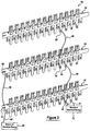
- Figure 3 is a perspective view of a terminal assembly which is dynamically configured in accordance with the teachings of the preferred embodiment of the invention.
-
- Referring now to Figures 1 and 2, there is shown a
terminal member 10 which is made in accordance with the teachings of the preferred embodiment of the invention. Particularly,terminal member 10 includes a generally planar and relativelywide body portion 12 which forms and/or integrally includes several substantially evenly spaced and outwardly protruding protrusions orblades 14 which have a respective longitudinal axis ofsymmetry 16 which is substantially orthogonal to the longitudinal axis ofsymmetry 18 of thebody portion 12. Each of the protrusions orblades 14 are each substantially coplanar to thebody portion 12. Particularly, thebody portion 12 and theprotruding blades 14 reside within substantially thesame plane 13. In another non-limiting embodiment,blades 14 may be unevenly spaced upon and/or formed bybody portion 12. - In the preferred embodiment of the invention, at least some of the
blades 14 include an insulation displacement portion or slottedaperture 20 which is formed upon respective blade insertion portions oredges 15 and which allows relatively large gauge and relatively high power conductors to be properly and operatively terminated upon theterminal 10 by "stripping" or respectively removing portions of the insulative cover or "sheath" containing the respectively received conductors, thereby allowing the respectively exposed conductors to physically and electrically contact theportions conductor containing aperture 20. Particularly, since theblades 14 are integrally formed with thebody portion 12, the relatively high-powered signals may be distributed along thebody 12 without substantially damaging theterminal 10. - Further,
terminal 10 includes several substantially identicalcomponent reception portions 22 which have afirst portion 24 which is substantially coplanar to thebody portion 12, which wholly resides withinplane 13, and which outwardly protrudes from thebody portion 12, in a direction opposite to the direction thatblades 14 protrude, and asecond portion 26 which is integrally formed withportion 24 and which resides in a plane which is substantially parallel to the plane which wholly contains thebody portion 12. Further,portions identical shoulders component reception slot 36 which is adapted to selectively receive a portion of an electrical component, effective to allow the received electrical component to be placed within one or more selectively formed circuits. Eachcomponent reception portion 22 has a longitudinal axis of symmetry 47 which is substantially parallel to the longitudinal axis ofsymmetry 16 and orthogonal to the longitudinal axis ofsymmetry 18, and eachportion 22 is "aligned" with a unique one of the blades 14 (i.e., residing above a unique one of the blades 14). -
Terminal 10 further includes several substantially identical and substantially and equally spaced or distributed connectors orcomponent reception portions 40 which cooperate withbody portion 12 to form a slottedaperture 42 which is adapted to selectively receive a component.Apertures 42 each have a longitudinal axis ofsymmetry 43 which is substantially parallel to the longitudinal axis of symmetry 47 of each of theapertures 36.Terminal 10 also includes at least one slottedinsulation displacement aperture 48 which resides upon thebody 12 along the longitudinal axis ofsymmetry 18 and which further is adapted to receive a component and/or conductor and allows relatively high electrical power signals to be coupled and/or communicated to thebody portion 12. In this manner,terminal member 10 includes a first "level" of insulation displacement apertures which reside uponedges 15 and a second "level" of insulation displacement apertures, such asaperture 48, which may be used to selectively receive a relatively high powered conductor (or other type of signal containing conductor), thereby allowing such electrical circuits to be formed even when theinsulation displacement portions 15 are hidden or substantially inaccessible due to, by way of example and without limitation, their respective placement within a circuit board assembly or other type of device or assembly. Further,body portion 12 includes ablade 27 which extends along the longitudinal axis ofsymmetry 18 and which further allows themember 10 to be contained within a reception cavity (not shown) in a direction alongaxis 18, thereby increasing the overall utility of theterminal member 10. - In a second embodiment of the invention, as best shown in Figure 2,
portions 40 are substantially curved in order to facilitate the efficient placement of certain electrical components within the slottedapertures 42. - Referring now to Figure 3, there is shown a
terminal assembly 50 which is made in accordance with the preferred embodiment of the invention. As shown,assembly 50 includes separate but substantiallyidentical terminal members terminal member 10 and which are selectively interconnected by use of relatively high powered bus orconductors - As shown,
conductor 58 is connected and/or received withininsulation displacement aperture 62 ofmember 52 and within theinsulation displacement aperture 64 ofmember 54.Conductor 60 is connected and/or received withininsulation displacement aperture 66 ofmember 54 and within theinsulation displacement aperture 68 ofmember 56.Conductor 70 is coupled to a first source ofelectrical energy 72 and toinsulation displacement aperture 74 ofterminal member 56.Conductor 80 is coupled to a second source ofelectrical power 82 and toinsulation displacement aperture 84 ofterminal member 56.Conductor 86 is coupled toinsulation displacement aperture 84 ofterminal member 56 and toinsulation displacement aperture 88 ofterminal member 54. - In this manner, it should be appreciated that electrical power may be selectively provided to terminal members such as
terminal members electrical sources reception slot 22, which is formed within these terminal members. That is, in this non-limiting example,conductors terminal members source 72 to theportion 62 of theterminal member 52.Conductor 60 provides such electrical power/energy to theterminal portion 66 ofterminal member 54.Conductor 86 communicates electrical power/energy fromterminal 56 to theinsulation displacement aperture 88 of theterminals 54. - It should be understood that the invention is not limited to the exact embodiment or method which has been previously delineated above, but that various changes and modifications may be made without departing from the spirit and the scope of the following claims.
Claims (11)
- A terminal member having a body portion including a first insulation displacement aperture and at least one blade which protrudes from said body portion and which includes a second insulation displacement aperture.
- The terminal member of claim 1 wherein said body has portion has a first longitudinal axis of symmetry and wherein said at least one protruding blade has a second longitudinal axis of symmetry which is orthogonal to said first longitudinal axis of symmetry.
- The terminal member of claim 2 wherein said first insulation displacement aperture resides along said first longitudinal axis of symmetry.
- The terminal member of claim 3 further including a component reception member which has a third longitudinal axis of symmetry which is orthogonal to said first longitudinal axis of symmetry and which is substantially parallel to said second longitudinal axis of symmetry.
- The terminal member of claim 4 wherein said component reception member is generally arcuate.
- A terminal member comprising an electrically conductive body having a plurality of blades which outwardly extend from said body in a first direction and which each respectively includes an insulation displacement portion, said body further forming a plurality of component reception members which are each aligned with a unique one of said plurality of blades and said body further having a longitudinal axis of symmetry along which at least one insulation displacement aperture is formed.
- The terminal member of claim 6 wherein said body further forms generally accurate second component reception members.
- The terminal member of claim 6 wherein said body further includes an integrally formed blade portion which extends along said longitudinal axis of symmetry.
- The terminal member of claim 8 wherein said plurality of component reception members extend in a second direction opposite to said first direction.
- The terminal member of claim 9 wherein said plurality of component reception members reside within a second plane.
- The terminal member of claim 10 wherein said plurality of blades reside with a second plane which is parallel to said first plane.
Applications Claiming Priority (2)
| Application Number | Priority Date | Filing Date | Title |
|---|---|---|---|
| US481821 | 2000-01-11 | ||
| US09/481,821 US6398580B2 (en) | 2000-01-11 | 2000-01-11 | Electrical terminal member |
Publications (2)
| Publication Number | Publication Date |
|---|---|
| EP1117150A1 true EP1117150A1 (en) | 2001-07-18 |
| EP1117150B1 EP1117150B1 (en) | 2004-08-04 |
Family
ID=23913517
Family Applications (1)
| Application Number | Title | Priority Date | Filing Date |
|---|---|---|---|
| EP00311323A Expired - Lifetime EP1117150B1 (en) | 2000-01-11 | 2000-12-18 | Electrical terminal member |
Country Status (3)
| Country | Link |
|---|---|
| US (1) | US6398580B2 (en) |
| EP (1) | EP1117150B1 (en) |
| DE (1) | DE60012678T2 (en) |
Cited By (1)
| Publication number | Priority date | Publication date | Assignee | Title |
|---|---|---|---|---|
| DE20306768U1 (en) * | 2003-05-02 | 2004-09-02 | Weidmüller Interface Gmbh & Co. | Insulation cutting and clamping system for ends of insulated electrical conductor wires, has terminals with cutting blades inside rectangular casing and connected to conductor strips |
Families Citing this family (12)
| Publication number | Priority date | Publication date | Assignee | Title |
|---|---|---|---|---|
| TWM280031U (en) * | 2005-07-01 | 2005-11-01 | Surtec Ind Inc | Pierce terminal parts |
| US7332674B2 (en) * | 2006-04-19 | 2008-02-19 | Delphi Technologies, Inc. | Electrical splice assembly |
| US7396264B2 (en) * | 2006-05-02 | 2008-07-08 | K.S. Terminals, Inc. | Electrical-tap connector |
| DE102012015581A1 (en) * | 2012-08-07 | 2014-02-13 | Rosenberger Hochfrequenztechnik Gmbh & Co. Kg | Connectors |
| US10098585B2 (en) | 2013-03-15 | 2018-10-16 | Cadwell Laboratories, Inc. | Neuromonitoring systems and methods |
| US9172170B2 (en) * | 2013-10-24 | 2015-10-27 | Asco Power Technologies, L.P. | Bus connector with reduced insertion force |
| US9287663B1 (en) | 2014-08-26 | 2016-03-15 | Lg Chem, Ltd. | Electrical connector and method of electrically coupling first and second electrical terminals of first and second battery cells to one another |
| US9935395B1 (en) | 2017-01-23 | 2018-04-03 | Cadwell Laboratories, Inc. | Mass connection plate for electrical connectors |
| US11992339B2 (en) | 2018-05-04 | 2024-05-28 | Cadwell Laboratories, Inc. | Systems and methods for dynamic neurophysiological stimulation |
| US11253182B2 (en) | 2018-05-04 | 2022-02-22 | Cadwell Laboratories, Inc. | Apparatus and method for polyphasic multi-output constant-current and constant-voltage neurophysiological stimulation |
| US11443649B2 (en) | 2018-06-29 | 2022-09-13 | Cadwell Laboratories, Inc. | Neurophysiological monitoring training simulator |
| US11139623B2 (en) * | 2020-01-14 | 2021-10-05 | Lear Corporation | Splice connector assembly |
Citations (4)
| Publication number | Priority date | Publication date | Assignee | Title |
|---|---|---|---|---|
| DE1751678U (en) * | 1957-07-18 | 1957-09-05 | Telefonbau & Normalzeit Gmbh | DISTRIBUTION BOARD FOR REMOTE INDICATORS, IN PARTICULAR TELEPHONE SYSTEMS. |
| US4533196A (en) * | 1981-09-19 | 1985-08-06 | Krone Gmbh | Device for making a solderless, non-screwed and unstripped single or multiple contact at a terminal element |
| DE4423339C1 (en) * | 1994-06-20 | 1995-09-21 | Krone Ag | Modular distribution strips for MDF for telephone and data leads |
| US5800215A (en) * | 1995-09-29 | 1998-09-01 | Krone Aktiengesellschaft | Distribution device for the telecommunication and data technique |
Family Cites Families (25)
| Publication number | Priority date | Publication date | Assignee | Title |
|---|---|---|---|---|
| GB1216575A (en) | 1967-07-12 | 1970-12-23 | Chemical Construction Corp | Recovery of power from heated gas streams |
| AR208483A1 (en) * | 1975-11-10 | 1976-12-27 | Amp Inc | ELECTRICAL TERMINAL |
| GB2125638B (en) * | 1982-08-09 | 1985-11-27 | Molex Inc | Multiguage insulation displacement connector and contacts therefor |
| DE3312754C1 (en) | 1983-04-09 | 1984-10-31 | Krone Gmbh, 1000 Berlin | Device with U-shaped LSA-PLUS connection contacts |
| US4586775A (en) | 1984-08-03 | 1986-05-06 | General Motors Corporation | Duplex insulation displacement terminal |
| US5026305A (en) * | 1990-06-28 | 1991-06-25 | Amp Incorporated | Connector for reed switch or similar electrical component |
| GB9124180D0 (en) * | 1991-11-14 | 1992-01-08 | Raychem Sa Nv | Electrical connector |
| US5194014A (en) * | 1992-05-20 | 1993-03-16 | Stewart Connector Systems, Inc. | Cable connector and contact terminal therefor |
| JP2830887B2 (en) | 1992-12-10 | 1998-12-02 | 矢崎総業株式会社 | Method of manufacturing joint terminal for bus bar and joint terminal |
| US5547391A (en) | 1993-03-11 | 1996-08-20 | Molex Incorporated | Commoning electrical connector |
| US5399098A (en) * | 1993-10-29 | 1995-03-21 | Molex Incorporated | Electrical connector and terminal therefor for mating with a blade contact |
| JP2885029B2 (en) * | 1993-11-22 | 1999-04-19 | 住友電装株式会社 | Method of manufacturing electric junction box containing bus bar and electric junction box manufactured by the method |
| KR0113849Y1 (en) * | 1994-05-07 | 1998-04-15 | 안영숙 | Electrical terminal |
| FR2720551B1 (en) * | 1994-05-25 | 1996-07-05 | Schneider Electric Sa | Self-stripping connector. |
| DE9416056U1 (en) * | 1994-10-06 | 1994-11-24 | Stocko Metallwarenfabriken Henkels Und Sohn Gmbh & Co, 42327 Wuppertal | Lockable blade receptacle for an electrical connection |
| US5622516A (en) | 1995-05-17 | 1997-04-22 | Lucent Technologies Inc. | Insulation displacement terminal with two-wire insertion capability |
| JPH097651A (en) | 1995-06-09 | 1997-01-10 | Minnesota Mining & Mfg Co <3M> | Contractor and terminal connector with that contractor |
| FR2739501B1 (en) * | 1995-09-29 | 1997-12-12 | Lacroix Jacques | CONNECTION DEVICE FOR HIGH DENSITY WIRE PATCHES |
| JP3251504B2 (en) * | 1996-07-25 | 2002-01-28 | 矢崎総業株式会社 | ID connector |
| DE59701532D1 (en) * | 1996-09-27 | 2000-05-31 | Tyco Electronics Logistics Ag | CONTACT ORGAN WITH DOUBLE CUTTING TERMINAL |
| US5888090A (en) * | 1997-02-19 | 1999-03-30 | Achee; Jamie S. | Lighting system for decorative miniature houses and village displays |
| US5902147A (en) | 1997-03-07 | 1999-05-11 | Circuit Assembly Corp. | Multi-conductor cable connector with integral grounding bus |
| US6142817A (en) * | 1997-03-07 | 2000-11-07 | Marconi Communications Inc. | Insulation displacement connector |
| US5975936A (en) * | 1997-09-03 | 1999-11-02 | Lucent Technologies Inc. | Blade carrier for use in a communication plug |
| US6280253B1 (en) * | 1999-04-22 | 2001-08-28 | Visteon Global Technologies, Inc. | Method and apparatus for selectively connecting electrical circuits and components |
-
2000
- 2000-01-11 US US09/481,821 patent/US6398580B2/en not_active Expired - Fee Related
- 2000-12-18 EP EP00311323A patent/EP1117150B1/en not_active Expired - Lifetime
- 2000-12-18 DE DE60012678T patent/DE60012678T2/en not_active Expired - Fee Related
Patent Citations (4)
| Publication number | Priority date | Publication date | Assignee | Title |
|---|---|---|---|---|
| DE1751678U (en) * | 1957-07-18 | 1957-09-05 | Telefonbau & Normalzeit Gmbh | DISTRIBUTION BOARD FOR REMOTE INDICATORS, IN PARTICULAR TELEPHONE SYSTEMS. |
| US4533196A (en) * | 1981-09-19 | 1985-08-06 | Krone Gmbh | Device for making a solderless, non-screwed and unstripped single or multiple contact at a terminal element |
| DE4423339C1 (en) * | 1994-06-20 | 1995-09-21 | Krone Ag | Modular distribution strips for MDF for telephone and data leads |
| US5800215A (en) * | 1995-09-29 | 1998-09-01 | Krone Aktiengesellschaft | Distribution device for the telecommunication and data technique |
Cited By (1)
| Publication number | Priority date | Publication date | Assignee | Title |
|---|---|---|---|---|
| DE20306768U1 (en) * | 2003-05-02 | 2004-09-02 | Weidmüller Interface Gmbh & Co. | Insulation cutting and clamping system for ends of insulated electrical conductor wires, has terminals with cutting blades inside rectangular casing and connected to conductor strips |
Also Published As
| Publication number | Publication date |
|---|---|
| DE60012678D1 (en) | 2004-09-09 |
| DE60012678T2 (en) | 2005-09-08 |
| EP1117150B1 (en) | 2004-08-04 |
| US6398580B2 (en) | 2002-06-04 |
| US20020001995A1 (en) | 2002-01-03 |
Similar Documents
| Publication | Publication Date | Title |
|---|---|---|
| US4867690A (en) | Electrical connector system | |
| US6398580B2 (en) | Electrical terminal member | |
| EP0107288A1 (en) | Electrical connector assembly for terminating flat shielded electrical cable | |
| EP1201505A3 (en) | Electrical junction box for a vehicle | |
| WO2002058191A2 (en) | Shielded electrical connector | |
| MY118192A (en) | High-speed edge connector | |
| US20010034165A1 (en) | Terminal block connector | |
| CA2363529A1 (en) | Press-fit bus bar for distributing power | |
| US4494816A (en) | Coaxial cable connector | |
| EP0820123A3 (en) | Edge connector for a printed circuit board | |
| US5709555A (en) | High density card edge connection system with outrigger and sequentially connected contacts | |
| EP0140473B1 (en) | Solderless circuit board conductor and connector assemblies employing same | |
| EP0554003A1 (en) | Dual readout extended socket | |
| EP1166400B1 (en) | Electrical connector | |
| CA2241692A1 (en) | Plug connector | |
| EP1440494B1 (en) | Connector system for interconnection with flat flexible circuitry | |
| EP0630081A1 (en) | Double sided connector for connection to an electrical cable | |
| EP1294055B1 (en) | Connector assembly comprising a tab-receiving insulated spring sleeve and a dual contact with pairs of spaced apart contact members and tails | |
| US20160181710A1 (en) | Printed Circuit Board Assembly Having Improved Terminals | |
| EP0612123A2 (en) | Programmable input-output electrical connector | |
| EP0037621A2 (en) | Electrical connector for use in establishing connections to a rectangular planar substrate | |
| US6261124B1 (en) | Connectors | |
| JPH10241805A (en) | Electric connector | |
| US6116948A (en) | Electrical connector for terminating discrete electrical wires | |
| KR950016464A (en) | IC Card Receptacle Mounting Device |
Legal Events
| Date | Code | Title | Description |
|---|---|---|---|
| PUAI | Public reference made under article 153(3) epc to a published international application that has entered the european phase |
Free format text: ORIGINAL CODE: 0009012 |
|
| AK | Designated contracting states |
Kind code of ref document: A1 Designated state(s): DE FR GB |
|
| AX | Request for extension of the european patent |
Free format text: AL;LT;LV;MK;RO;SI |
|
| 17P | Request for examination filed |
Effective date: 20020104 |
|
| AKX | Designation fees paid |
Free format text: DE FR GB |
|
| 17Q | First examination report despatched |
Effective date: 20030724 |
|
| GRAP | Despatch of communication of intention to grant a patent |
Free format text: ORIGINAL CODE: EPIDOSNIGR1 |
|
| GRAS | Grant fee paid |
Free format text: ORIGINAL CODE: EPIDOSNIGR3 |
|
| GRAA | (expected) grant |
Free format text: ORIGINAL CODE: 0009210 |
|
| AK | Designated contracting states |
Kind code of ref document: B1 Designated state(s): DE FR GB |
|
| PG25 | Lapsed in a contracting state [announced via postgrant information from national office to epo] |
Ref country code: FR Free format text: LAPSE BECAUSE OF FAILURE TO SUBMIT A TRANSLATION OF THE DESCRIPTION OR TO PAY THE FEE WITHIN THE PRESCRIBED TIME-LIMIT Effective date: 20040804 |
|
| REG | Reference to a national code |
Ref country code: GB Ref legal event code: FG4D |
|
| REF | Corresponds to: |
Ref document number: 60012678 Country of ref document: DE Date of ref document: 20040909 Kind code of ref document: P |
|
| PLBE | No opposition filed within time limit |
Free format text: ORIGINAL CODE: 0009261 |
|
| STAA | Information on the status of an ep patent application or granted ep patent |
Free format text: STATUS: NO OPPOSITION FILED WITHIN TIME LIMIT |
|
| 26N | No opposition filed |
Effective date: 20050506 |
|
| EN | Fr: translation not filed | ||
| PGFP | Annual fee paid to national office [announced via postgrant information from national office to epo] |
Ref country code: GB Payment date: 20071218 Year of fee payment: 8 |
|
| PGFP | Annual fee paid to national office [announced via postgrant information from national office to epo] |
Ref country code: DE Payment date: 20071221 Year of fee payment: 8 |
|
| GBPC | Gb: european patent ceased through non-payment of renewal fee |
Effective date: 20081218 |
|
| PG25 | Lapsed in a contracting state [announced via postgrant information from national office to epo] |
Ref country code: DE Free format text: LAPSE BECAUSE OF NON-PAYMENT OF DUE FEES Effective date: 20090701 |
|
| PG25 | Lapsed in a contracting state [announced via postgrant information from national office to epo] |
Ref country code: GB Free format text: LAPSE BECAUSE OF NON-PAYMENT OF DUE FEES Effective date: 20081218 |