EP1117116A2 - Cathode ray tube having an improved indirectly heated cathode structure - Google Patents
Cathode ray tube having an improved indirectly heated cathode structure Download PDFInfo
- Publication number
- EP1117116A2 EP1117116A2 EP01100024A EP01100024A EP1117116A2 EP 1117116 A2 EP1117116 A2 EP 1117116A2 EP 01100024 A EP01100024 A EP 01100024A EP 01100024 A EP01100024 A EP 01100024A EP 1117116 A2 EP1117116 A2 EP 1117116A2
- Authority
- EP
- European Patent Office
- Prior art keywords
- cathode
- heater
- ray tube
- cathode ray
- coating film
- Prior art date
- Legal status (The legal status is an assumption and is not a legal conclusion. Google has not performed a legal analysis and makes no representation as to the accuracy of the status listed.)
- Withdrawn
Links
- 239000011248 coating agent Substances 0.000 claims abstract description 58
- 238000000576 coating method Methods 0.000 claims abstract description 58
- 238000010438 heat treatment Methods 0.000 claims abstract description 40
- 229910052751 metal Inorganic materials 0.000 claims abstract description 12
- 239000002184 metal Substances 0.000 claims abstract description 12
- 239000000463 material Substances 0.000 claims abstract description 9
- 239000010953 base metal Substances 0.000 claims abstract description 8
- PNEYBMLMFCGWSK-UHFFFAOYSA-N aluminium oxide Inorganic materials [O-2].[O-2].[O-2].[Al+3].[Al+3] PNEYBMLMFCGWSK-UHFFFAOYSA-N 0.000 claims description 27
- 238000010894 electron beam technology Methods 0.000 claims description 23
- WFKWXMTUELFFGS-UHFFFAOYSA-N tungsten Chemical compound [W] WFKWXMTUELFFGS-UHFFFAOYSA-N 0.000 claims description 20
- OAICVXFJPJFONN-UHFFFAOYSA-N Phosphorus Chemical compound [P] OAICVXFJPJFONN-UHFFFAOYSA-N 0.000 claims description 17
- 239000000843 powder Substances 0.000 claims description 13
- UONOETXJSWQNOL-UHFFFAOYSA-N tungsten carbide Chemical compound [W+]#[C-] UONOETXJSWQNOL-UHFFFAOYSA-N 0.000 claims description 4
- 239000010410 layer Substances 0.000 description 25
- 238000004804 winding Methods 0.000 description 19
- 229910052721 tungsten Inorganic materials 0.000 description 13
- 239000010937 tungsten Substances 0.000 description 13
- 238000000034 method Methods 0.000 description 9
- 238000003466 welding Methods 0.000 description 8
- 239000007789 gas Substances 0.000 description 7
- 239000011521 glass Substances 0.000 description 7
- 238000004070 electrodeposition Methods 0.000 description 6
- 239000002356 single layer Substances 0.000 description 5
- 238000004519 manufacturing process Methods 0.000 description 4
- LFQSCWFLJHTTHZ-UHFFFAOYSA-N Ethanol Chemical compound CCO LFQSCWFLJHTTHZ-UHFFFAOYSA-N 0.000 description 3
- RTZKZFJDLAIYFH-UHFFFAOYSA-N Diethyl ether Chemical compound CCOCC RTZKZFJDLAIYFH-UHFFFAOYSA-N 0.000 description 2
- QVGXLLKOCUKJST-UHFFFAOYSA-N atomic oxygen Chemical compound [O] QVGXLLKOCUKJST-UHFFFAOYSA-N 0.000 description 2
- 239000011324 bead Substances 0.000 description 2
- 230000008901 benefit Effects 0.000 description 2
- 238000006243 chemical reaction Methods 0.000 description 2
- 239000003086 colorant Substances 0.000 description 2
- 238000005336 cracking Methods 0.000 description 2
- 238000003618 dip coating Methods 0.000 description 2
- 235000019441 ethanol Nutrition 0.000 description 2
- YIXJRHPUWRPCBB-UHFFFAOYSA-N magnesium nitrate Chemical compound [Mg+2].[O-][N+]([O-])=O.[O-][N+]([O-])=O YIXJRHPUWRPCBB-UHFFFAOYSA-N 0.000 description 2
- 239000000203 mixture Substances 0.000 description 2
- 239000001301 oxygen Substances 0.000 description 2
- 229910052760 oxygen Inorganic materials 0.000 description 2
- 230000002093 peripheral effect Effects 0.000 description 2
- XLYOFNOQVPJJNP-UHFFFAOYSA-N water Substances O XLYOFNOQVPJJNP-UHFFFAOYSA-N 0.000 description 2
- BNGXYYYYKUGPPF-UHFFFAOYSA-M (3-methylphenyl)methyl-triphenylphosphanium;chloride Chemical compound [Cl-].CC1=CC=CC(C[P+](C=2C=CC=CC=2)(C=2C=CC=CC=2)C=2C=CC=CC=2)=C1 BNGXYYYYKUGPPF-UHFFFAOYSA-M 0.000 description 1
- NTIZESTWPVYFNL-UHFFFAOYSA-N Methyl isobutyl ketone Chemical compound CC(C)CC(C)=O NTIZESTWPVYFNL-UHFFFAOYSA-N 0.000 description 1
- UIHCLUNTQKBZGK-UHFFFAOYSA-N Methyl isobutyl ketone Natural products CCC(C)C(C)=O UIHCLUNTQKBZGK-UHFFFAOYSA-N 0.000 description 1
- ZOKXTWBITQBERF-UHFFFAOYSA-N Molybdenum Chemical compound [Mo] ZOKXTWBITQBERF-UHFFFAOYSA-N 0.000 description 1
- 239000000020 Nitrocellulose Substances 0.000 description 1
- 239000002253 acid Substances 0.000 description 1
- 230000009471 action Effects 0.000 description 1
- 238000004458 analytical method Methods 0.000 description 1
- 230000004323 axial length Effects 0.000 description 1
- 239000011230 binding agent Substances 0.000 description 1
- 238000012937 correction Methods 0.000 description 1
- 238000000354 decomposition reaction Methods 0.000 description 1
- 230000002950 deficient Effects 0.000 description 1
- 238000007598 dipping method Methods 0.000 description 1
- 239000012153 distilled water Substances 0.000 description 1
- 238000001035 drying Methods 0.000 description 1
- 239000003792 electrolyte Substances 0.000 description 1
- 238000005516 engineering process Methods 0.000 description 1
- 238000010304 firing Methods 0.000 description 1
- 238000009413 insulation Methods 0.000 description 1
- 238000012423 maintenance Methods 0.000 description 1
- 238000012986 modification Methods 0.000 description 1
- 230000004048 modification Effects 0.000 description 1
- 229910052758 niobium Inorganic materials 0.000 description 1
- 239000010955 niobium Substances 0.000 description 1
- GUCVJGMIXFAOAE-UHFFFAOYSA-N niobium atom Chemical compound [Nb] GUCVJGMIXFAOAE-UHFFFAOYSA-N 0.000 description 1
- 229920001220 nitrocellulos Polymers 0.000 description 1
- 238000003825 pressing Methods 0.000 description 1
- 238000012545 processing Methods 0.000 description 1
- 230000005855 radiation Effects 0.000 description 1
- 230000009467 reduction Effects 0.000 description 1
- 239000004065 semiconductor Substances 0.000 description 1
- HBMJWWWQQXIZIP-UHFFFAOYSA-N silicon carbide Chemical compound [Si+]#[C-] HBMJWWWQQXIZIP-UHFFFAOYSA-N 0.000 description 1
- 229910010271 silicon carbide Inorganic materials 0.000 description 1
- 238000001179 sorption measurement Methods 0.000 description 1
- 125000006850 spacer group Chemical group 0.000 description 1
- 229910052715 tantalum Inorganic materials 0.000 description 1
- GUVRBAGPIYLISA-UHFFFAOYSA-N tantalum atom Chemical compound [Ta] GUVRBAGPIYLISA-UHFFFAOYSA-N 0.000 description 1
- 230000007704 transition Effects 0.000 description 1
- 238000005406 washing Methods 0.000 description 1
Images


Classifications
-
- H—ELECTRICITY
- H01—ELECTRIC ELEMENTS
- H01J—ELECTRIC DISCHARGE TUBES OR DISCHARGE LAMPS
- H01J1/00—Details of electrodes, of magnetic control means, of screens, or of the mounting or spacing thereof, common to two or more basic types of discharge tubes or lamps
- H01J1/02—Main electrodes
- H01J1/13—Solid thermionic cathodes
- H01J1/20—Cathodes heated indirectly by an electric current; Cathodes heated by electron or ion bombardment
-
- H—ELECTRICITY
- H01—ELECTRIC ELEMENTS
- H01J—ELECTRIC DISCHARGE TUBES OR DISCHARGE LAMPS
- H01J29/00—Details of cathode-ray tubes or of electron-beam tubes of the types covered by group H01J31/00
- H01J29/02—Electrodes; Screens; Mounting, supporting, spacing or insulating thereof
- H01J29/04—Cathodes
-
- H—ELECTRICITY
- H01—ELECTRIC ELEMENTS
- H01J—ELECTRIC DISCHARGE TUBES OR DISCHARGE LAMPS
- H01J1/00—Details of electrodes, of magnetic control means, of screens, or of the mounting or spacing thereof, common to two or more basic types of discharge tubes or lamps
- H01J1/02—Main electrodes
- H01J1/13—Solid thermionic cathodes
- H01J1/20—Cathodes heated indirectly by an electric current; Cathodes heated by electron or ion bombardment
- H01J1/22—Heaters
-
- H—ELECTRICITY
- H01—ELECTRIC ELEMENTS
- H01J—ELECTRIC DISCHARGE TUBES OR DISCHARGE LAMPS
- H01J2201/00—Electrodes common to discharge tubes
- H01J2201/28—Heaters for thermionic cathodes
- H01J2201/2803—Characterised by the shape or size
- H01J2201/2867—Spiral or helix
Definitions
- the present invention relates to a cathode ray tube having an electron gun employing an indirectly heated cathode, and in particular to a highly-reliable long-life cathode ray tube having prevented occurrence of leakage current by improving insulating characteristics between a cathode sleeve and a heater of the indirectly heated cathode.
- Cathode ray tubes used for a color television receiver, a display monitor and the like are widely used in various fields as display means because of their capability of reproducing high-definition images.
- Cathode ray tube of this kind includes a vacuum envelope formed of a panel portion, a neck portion and a funnel portion for connecting the panel portion and the neck portion, a phosphor screen formed of phosphors coated on an inner surface of the panel portion, an electron gun housed in the neck portion, and comprised of a plurality of electrodes such as an indirectly heated cathode, a control electrode and an accelerating electrode for projecting an electron beam toward the phosphor screen, and a deflection yoke mounted around the funnel portion for scanning the electron beam emitted from the electron gun over the phosphor screen.
- the electron gun usually employs an indirectly heated cathode.
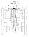
- FIG. 5 is a cross-sectional view of an essential part of an indirectly heated cathode and its vicinity of a prior art cathode ray tube.
- reference numeral 51 denotes an indirectly heated cathode structure
- the indirectly heated cathode structure 51 comprises a tubular cathode sleeve 52, a cap-shaped cathode cap 53 fixed at an end of the cathode sleeve 52, an electron-emissive material layer 54 coated on a top surface of the cathode cap 53, and a heater 55 a portion of which is disposed within the cathode sleeve 52 for heating the cathode cap 53.
- a portion of a spirally wound heating wire 55a of the heater 55 is covered with an insulating film 55b made chiefly of alumina and a coating film 55c containing alumina and tungsten powder.
- the insulating film 55b covers all the heating wire 55a of the heater 55 extending to ends 55e except for end portions 55d for welding
- the coating film 55c covers the outer surface of approximately all the insulating film 55b except for the vicinity of the ends 55e of the insulating film 55b extending from a coil portion 55f on the side of the top of the cathode sleeve 52 to ends 55g beyond a flared bottom end 52a of the cathode sleeve 52.
- the coating film 55c contains a small amount of tungsten powder as described above and appears black, and the insulating film 55b is made chiefly of alumina and appears white, but the heater 55 appears black as a whole, and this type of heaters are generally called dark heaters.
- the heater 55 is welded to heater supports 56 at its end portions 55d for welding.
- the cathode sleeve 52 is fixed to a small-diameter portion of a cathode cylinder 58, a large-diameter portion of which is fixed to a tubular cathode support eyelet 57.
- the cathode support eyelet 57 and the heater supports 56 are fixed to a pair of multiform glasses 61 via bead supports 59 and via heater lead straps 60, respectively.
- Reference numeral 62 denotes a control electrode which is fixed to the multiform glasses 61 with a desired spacing between it and the electron-emissive material layer 54.
- Japanese Patent Publication No. Hei 8-3976 discloses a technique for improving withstand voltage characteristics by preventing deformation and cracking of an insulating alumina film of a heater using insulating alumina powder of specified average diameters.
- Japanese Patent Application Laid-open No. Hei 7-161282 (laid-open on June 23, 1995) discloses a technique for suppressing a leakage current between a heater and a cathode by combining a dark heater with a cathode sleeve having a silicon carbide film on its inner surface.
- Japanese Patent Application Laid-open No. Hei 11-213859 discloses atechnique for suppressing a leakage current between a heater and a cathode by dispersing at least one of niobium and tantalum in a film made of a mixture of tungsten and alumina and coated on at least one of an inner surface of a cathode sleeve and a surface of the heater.
- Japanese Patent Application Laid-open No. Hei 11-273549 discloses atechnique for suppressing a leakage current between a heater and a cathode by improving purity of alumina used for insulation of the heater and thereby increasing electrical resistance of the alumina itself.
- Japanese Utility Model Publication No. Sho 60-3483 discloses a technique for preventing cracking of alumina by extending a dark-film region to cover a three-layer winding portion of each leg portion of a heater.
- Cathode ray tubes employing such dark heaters have a feature in that heat can be efficiently radiated from a heater because the outer surface of the heater is darkened and thereby heat radiation efficiency of the surface of the heater is increased, and consequently, their reliability can be improved.
- the alumina film serving as a heater insulating film is heated by the leakage current, oxygen escapes from the alumina due to the heat, and electrical conductivity occurs in the oxygen-deficient alumina (Al 2 O 2.99 ).
- the heater is sometimes broken by a further increase in the leakage current, and therefore it is important in view of ensuring reliability of a cathode ray tube to prevent the leakage current between the heater and the cathode.
- Tungsten present within a cathode ray tube is used in the heating wire 55a of the heater 55 and the above-mentioned coating film 55c. If the two are compared with each other, tungsten contained in the coating film 55c is of a small powder size of about 1.0 ⁇ m in diameter, and is chemically active compared with the heating wire 55a.
- the degree of vacuum of the cathode ray tube is poorest immediately after flashing of getters in the manufacturing step, that is, about 10 -2 Pa. After flashing of the getters, decomposition of residual gases within the tube by an electron beam and adsorption of the residual gases by the getter film provide the ultimate degree of vacuum of about 10 -5 Pa. It was found out that the mean free paths of the residual gases are about several tens cm in the poorest degree of vacuum (about 10 -2 Pa) and the residual gases react with portions having directly exposed tungsten within the tube.
- a second one of the two causes for occurrence of the leakage current between the heater and the cathode is occurrence of the leakage current due to the physical contact between the heater and the cathode sleeve. This is caused by the fact that leg portions of the heater 55 are pulled apart when the leg portions of the heater 55 are welded to heater supports 56 and the contact area between the heater and the cathode sleeve 52 is increased in the vicinity of the flared bottom end 52a of the cathode sleeve 52.
- the present invention provides a superior cathode ray tube having prevented the leakage current between the heater and the cathode by specifying a relationship between a cathode sleeve of an indirectly heated cathode of an electron gun and a coating length of a coating film of the heater inserted in the cathode sleeve such that collisions and consequent reactions between the residual gases within the tube and the coating film of the heater are reduced and at the same time the contact area between the heater and the cathode sleeve is reduced.
- a cathode ray tube having an evacuated envelope including a panel portion, a neck portion, a funnel portion for connecting the panel portion and the neck portion and a stem having a plurality of pins therethrough and being sealed to close the neck portion at one end thereof, a phosphor screen formed on an inner surface of the panel portion, an electron gun housed in the neck portion, the electron gun having an indirectly heated cathode structure and a plurality of electrodes disposed downstream of the indirectly heated cathode structure, spaced specified distances apart, arranged axially in a specified order, and fixed by insulating rods for projecting an electron beam toward the phosphor screen, and a deflection yoke mounted around a vicinity of a transitional region between the neck portion and the funnel portion for scanning the electron beam on the phosphor screen, the indirectly heated cathode structure comprising: a base metal having an electron emissive material coating on an outer top surface thereof; a metal sle
- FIG. 1 is a cross-sectional view of an essential part of an indirectly heated cathode structure and its vicinity in an embodiment of a cathode ray tube in accordance with the present invention.
- reference numeral 1 denotes an indirectly heated cathode structure.
- the indirectly heated cathode structure 1 includes a cylindrical sleeve 2, a cap-shaped cathode cap 3 fixed at an end of the cathode sleeve 2, an electron-emissive material layer 4 coated on a top surface of the cathode cap 3, and a heater 5 a portion of which is disposed in the cathode sleeve 2 for heating the cathode cap 3.
- a portion of a spirally wound heating wire 5a of the heater 5 is coated with two layers of an insulating film 5b made chiefly of alumina and a coating film 5c containing alumina and tungsten fine powder.
- the insulating film 5b covers all the heating wire 5a of the heater 5 extending from ends 5e to a coiled portion 5f on a top side of the cathode sleeve 2 except for end portions 5d for welding, and the coating film 5c covers outer surfaces of the insulating film 55b extending from the coiled portion 5f on a top side of the cathode sleeve 2 to ends 5g within a flared bottom end 2a of the cathode sleeve 2.
- the edges 5g of the coating film 5c is displaced toward the coiled portion 5f from the ends 5e of the insulating film 5b on the sides of the end portions 5d for welding and is within the flared bottom end 2a of the cathode sleeve 2 such that the ends 5g of the coating film 5c are displaced toward the electron-emissive material layer 4 from the bottom ends 2a.
- the coating film 5c contains alumina and tungsten powder, and is a black coating film which appears black, and on the other hand, the insulating film 5b is made chiefly of alumina, and therefore is a white insulating film which appears white.
- the whole of the black coating film of the heater is disposed within the cathode sleeve, contacts and consequent reactions between the residual gases within the tube and the black coating film are reduced and therefore tungsten does not disperse into alumina, and consequently, dielectric strength characteristics of alumina are not degraded and therefore the leakage current is prevented.
- the thickness of the insulating film of the heater in the vicinity of the flared portion of the cathode sleeve is reduced, and therefore the contact area between the cathode sleeve and the heater is reduced such that the leakage current is prevented.
- the insulating film 5b may be formed of a plurality of sub-layers each containing alumina powder different in size, for example, and also the coating 5c may be formed of a plurality of sub-layers containing alumina powder different in size or containing tungsten different in proportion, for example.
- the heater 5 is welded to heater supports 6 at its end portions 5d for welding.
- the cathode sleeve 2 is fixed to a small-diameter portion of a cathodecylinder 8, a large-diameter portion of which is fixed to a tubular cathode support eyelet 7.
- the cathode support eyelet 7 and the heater supports 6 are fixed to a pair of multiform glasses 11 via bead supports 9 and via heater lead straps 10, respectively.
- Reference numeral 12 denotes a control electrode which is fixed to the multiform glasses 11 with a desired spacing between it and the electron-emissive material layer 4.
- FIGS. 2A to 2C are detailed views of an example of the heater of FIG. 1, FIG. 2A is a plan view thereof, FIG. 2B is a side elevation view along section line IIB-IIB of the heater of FIG. 2A and FIG. 2C is an enlarged cross-sectional view of the circled portion, designated "A", of the heater of FIG. 2A.
- the same reference numerals as utilized in FIG. 1 designate corresponding portions in FIGS. 2A to 2C.
- the heater 5 is covered with the insulating film 5b in a region extending a length L2 of the overall length L1 except for the end portions 5d for welding, and further an outer surface of the insulating film 5b is covered with the coating film 5c in a region extending from the coiled portion 5f toward the end portions 5d for welding as far as the ends 5g except for a single-layer portion L3.
- Reference character L4 denotes a length of the overlapped portion of the insulating film 5b and the coating film 5c
- L5 is a single-layer winding portion of the heating wire 5a
- L6 is a plural-layer winding portion of the heating wire 5a.
- a three-layer winding configuration disclosed in U.S. Pat. No. 4,149,104 issued on Apr. 10, 1979 (which corresponds to Japanese Utility Model Publication Sho 57-34671 published on July 30, 1982) may be employed.
- reference character D denotes a diameter of a hollow formed in the heater by dissolving a winding mandrel
- d is a diameter of the heating wire 5a
- p is a winding pitch of the heating wire 5a
- tl is a thickness of the insulating film 5b
- t2 is a thickness of the coating film 5c.
- a tungsten wire of 0.032 mm in diameter for the heating wire 5a is wound around a mandrel made of a molybdenum wire of 0.15 mm in diameter with a pitch of 15 turns/mm for the single-layer winding portion L5 and the plural-layer winding portions L6 employs a three-layer winding structure disclosed in U.S. Pat. No. 4, 149, 104 (which corresponds to Japanese Utility Model Publication Sho 57-34671).
- the wound heating wire is cut to a specified length, and then is again wound spirally to form the double helical single-layer winding portion L5.
- the heater is coated with the insulating film 5b in a region designated as L2, of the overall length L1 except for the end portions 5d for welding by using a technique of electrodeposition.
- the coating thickness by electrodeposition is chosen such that the thickness of the insulating film 5b becomes about 80 ⁇ m after it is fired at about 1600 °C.
- One liter of a solution for electrodepositing the insulating film 5b is composed of 670 grams of 99.85%-pure powdered alumina (4.4 ⁇ m inaveragediameter), 440 ml of denature alcohol and 440 ml of distilled water, and the solution is mixed with 14 grams of each of magnesium nitrate and aluminum nitrate which act as electrolytes.
- the electrodeposition was carried out with the heater connected to a negative terminal of a 70 V power source.
- the thickness of the alumina coating film is controlled by adjusting the length of time for electrodeposition.
- the black coating film 5c is formed on a portion of L4 in length of the insulating film 5b except for the'single-layer film portion designated "L3" to a thickness of about 10 ⁇ m by using a dip coating technique which is disclosed in Japanese Patent Publication Hei 6-22095 (published on March 23, 1994).
- One liter of a solution for coating the black coating film 5c is roughly composed of 450 grams of the same powdered alumina as used in the solution for the electrodeposition of the insulating film 5b, 220 grams of tungsten fine powder of 1 ⁇ m in average diameter, 700 grams of methyl isobutyl ketone and 110 ml of ethyl ether and is mixed with 17 grams of nitrocellulose which acts as a binder.
- the coating thickness is thinned to be 10 ⁇ m by washing the black coating film 5c using ethyl alcohol.
- the coating length of the coating film 5c is easily controlled by adjusting a depth of dipping into the black coating solution.
- the tungsten fine powder was used for the black coating film 5c, but tungsten carbide fine powder can also be used for the black coating film 5c instead of the tungsten fine powder.
- a mixture of tungsten fine powder and tungsten carbide fine powder can also be used for the black coating film 5c.
- FIG. 3 is a side view of an example of an electron gun used for a cathode ray tube of the present invention employing an indirectly heated cathode structure shown in FIG. 1, and the same reference numerals as utilized in FIG. 1 designate corresponding portions in FIG. 3.
- the electron gun of FIG. 3 comprises a control electrode (the first grid electrode, G1) 12, an accelerating electrode (the second grid electrode, G2) 22, focus electrodes (the third grid electrode, G3; the fourth grid electrode, G4; and the fifth grid electrode, G5) 23, 24, 25, an anode (the sixth grid electrode, G6) and a shield cup 27 axially arranged in a specified order with specified spacings therebetween and fixed on a pair of multiform glasses 11, and tabs provided to or leads connected to the respective electrodes are connected to corresponding ones of stem pins 28a implanted in a stem 28.
- the indirectly heated cathode structure 1 is closely spaced from the control electrode 12 toward the stem 28, and housed within the indirectly heated cathode structure 1 is the heater 5 for heating the electron-emissive material layer described in connection with FIGS. 2A to 2C.
- Reference numeral 29 denote bulb spacer contacts which serve to align the axis of the electron gun with the longitudinal axis of the tube by pressing on an inner wall of a neck portion of a vacuum envelope of the cathode ray tube resiliently, and to introduce an anode voltage to the electron gun from an internal conductive film coated on the inner walls of the funnel and neck portions of the vacuum envelope.
- the control electrode 12, the accelerating electrode 22 and the indirectly heated cathode 1 form an electron beam generating section (a triode section).
- the focus electrodes 23 to 25 accelerate and focus electron beams emitted from the electron beam generating section, and then a main lens formed between the focus electrode 25 and the anode 26 exerts a specified focusing action on the electron beams and directs the electron beams toward a phosphor screen.
- the stem 28 is fused and bonded to an open end of the neck portion of the vacuum envelope, and external signals and voltages are applied to corresponding ones of the electrodes via the stem pins 28a.
- FIG. 4 is a schematic longitudinal cross-sectional view of a shadow mask type color cathode ray tube in accordance with an embodiment of a cathode ray tube of the present invention for explaining its overall structure roughly.
- reference numeral 31 denotes a panel portion
- 32 is a neck portion
- 33 is a funnel portion
- 34 is a phosphor film
- 35 is shadow mask having a large number of electron beam apertures therein and serving as a color selection electrode, which is disposed coaxially with the phosphor film 34 and is spaced a predetermined distance from the phosphor film 34.
- Reference numeral 36 denotes a mask frame which holds the shadow mask 35 in place and others with a structure to be described subsequently.
- Reference numeral 37 are springs, 38 are panel pins, 39 is a magnetic shield for shielding an external magnetic field (the Earth's magnetic field) and preventing trajectories of the electron beams from being changed by the Earth's magnetic field, 40 is an anode button, 41 is an internal conductive coating, 42 is a deflection yoke for deflecting the electron beams horizontally and vertically, 43 is an electron gun having an indirectly heated cathode for emitting three electron beams 44 (a center electron beam and two side electron beams).
- Reference 45 denotes an external magnetic correction device (a magnet assembly) which has a function of correcting misregister between electron beam spots and phosphor elements caused by delicate eccentricity between the electron gun and an assembly of the panel portion, the funnel portion and the shadow mask, or rotational misalignment between the electron gun and the assembly of the panel portion, the funnel portion and the shadow mask.
- an external magnetic correction device a magnet assembly
- the mask frame 36 having fixed thereto the shadow mask 35, the magnetic shield 39 and others is mounted on the panel pins 38 via the springs 37 within a bulb comprised of the panel portion 31 having the phosphor film 34 on its inner surface and the funnel portion 33, then the panel portion 31 and the funnel portion 33 are joined together with fused frit glass, the electron gun 43 is sealed into the neck portion 32, and the envelope formed of the panel portion 31, the funnel portion 33 and the neck portion 32 is vacuum-sealed.
- the electron beams 44 emitted from the electron gun 43 are modulated by video signals from an external signal processing circuit (not shown), are projected toward the phosphor screen 34, and are deflected horizontally and vertically by the deflection yoke 42 mounted around the transition region between the neck portion 32 and the funnel portion 33, then pass through electron beam apertures in the shadow mask 35 serving as the color selection electrode and impinge upon the phosphor film 34 to form images.
- the embodiment of the present invention shown in FIG. 4 is a shadow mask type color cathode ray tube of the flat-screen type.
- the outer surface of the panel portion 31 is approximately flat, and its inner surface is concavely curved.
- the shadow mask 35 is fabricated by press-forming a shadow mask blank into a shape having a specified curvature conforming to the inner surface of the panel portion 31.
- the reason why the inner surface of the panel portion 31 and the shadow mask 35 are curved irrespective of the approximately flat outer surface of the panel portion 31 is that a method of fabricating the shadow mask 5 by a press-forming technique is simple and the cost of the shadow mask 5 is low.
- Amajor surface of the shadowmask 35 including an apertured area formed with a large number of electron beam apertures is approximately rectangular, has different radiuses of curvature along the major axis, the minor axis and the diagonals, of the major surface, respectively. This is intended to obtain the compatibility of creation of a sense that a picture on the screen of the color cathode ray tube is flat, with the maintenance of mechanical strength of the formed shadow mask.
- the curved surface of the shadow mask 35 in the present embodiment is aspheric, and the radiuses of curvature of the shadow mask 35 decrease gradually with increasing distance from the center of the major surface of the shadow mask 35 toward the peripheries of the major surface, along the major axis, the minor axis and the diagonals of the major surface, respectively.
- the radius Rx of curvature along the major axis varies from 1450 mm to 1250 mm
- the radius Ry of curvature along the minor axis varies from 2000 mm to 1300 mm
- the radius Rd of curvature along the diagonals varies from 1600 mm to 1250 mm.
- the end of the overlapped portion of the insulating film and the coating film in the present invention is within the cathode sleeve and is away from the flared bottom end of the cathode sleeve, and consequently, the contact area between the cathode sleeve and the heater in the present invention is made smaller than that in the prior art, and it is thought that this fact also contributes to the reduction of the leakage current between the heater and the cathode.
- the plural-layer winding configuration of the leg portions had a disadvantage in that it increases the diameter of the heater in the vicinity of the bottom end of the cathode sleeve, and consequently, it increases the contact area between the heater and the vicinity of the bottom end of the cathode sleeve.
- the above configuration of the present invention has eliminated the above disadvantage by reducing the contact area between the coating film formed on the insulating film of the heater and the vicinity of the bottom end of the cathode sleeve.
- the present invention specifies a positional relationship between the insulating film and the coating film of the heater and the cathode sleeve in the indirectly heated cathode structure of an electron gun used for a cathode ray tube, thereby preventing the leakage current between the heater and the cathode and consequently, making it possible to employ an automatic cutoff-voltage control circuit for a monitor set or the like and thereby facilitate the adjustment of the monitor set or the like, prevent breakage of the heater and short circuit between the heater and the cathode, and consequently, the present invention provides a cathode ray tube superior in reliability.
Landscapes
- Electrodes For Cathode-Ray Tubes (AREA)
Abstract
Description
Wall thickness = 0.018 mm,
Outside diameter = 1.6 mm,
Axial length = 7 mm.
Overall length L1 = 13 mm,
Coating length L2 of the insulating film 5b = 9.5 mm,
Coating length L4 of the coating film 5c = 6 mm,
Coating thickness tl = 80 µm,
Coating thickness t2 = 10 µm.
Claims (6)
- A cathode ray tube having an evacuated envelope including a panel portion (31), a neck portion (32), a funnel portion (33) for connecting said panel portion and said neck portion and a stem having a plurality of pins therethrough and being sealed to close said neck portion at one end thereof, a phosphor screen (34) formed on an inner surface of said panel portion, an electron gun (43) housed in said neck portion, said electron gun having an indirectly heated cathode structure (1) and a plurality of electrodes disposed downstream of said indirectly heated cathode structure, spaced specified distances apart, arranged axially in a specified order, and fixed by insulating rods for projecting an electron beam (44) toward said phosphor screen, and a deflection yoke (42) mounted around a vicinity of a transitional region between said neck portion and said funnel portion for scanning the electron beam on said phosphor screen,
said indirectly heated cathode structure (1) comprising:a base metal (3) having an electron emissive material coating (4) on an outer top surface thereof;a metal sleeve (2) having said base metal attached to a first end of said metal sleeve and having a second end opposite from said first end;a heater (5) housed partly within said metal sleeve, said heater including a major heating portion having a spirally wound heating wire (5f) and leg portions (5g) connected to respective ends of said major heating portion and comprising heating wires (5a) wound spirally in a plurality of layers;an insulating film (5b) covering said major heating portion and a portion of each of said leg portions continuous with said major heating portion; anda black coating film (5c) covering a portion of said insulating film extending from said major heating portion toward each of said leg portions, a whole of said black coating film being housed within said metal sleeve. - A cathode ray tube according to claim 1, wherein said insulating film (5b) is made of alumina.
- A cathode ray tube according to claim 1, wherein said black coating film (5c) contains at least one of tungsten powder and tungsten carbide powder.
- A cathode ray tube according to claim 2, wherein said black coating film contains at least one of tungsten powder and tungsten carbide powder.
- A cathode ray tube according to one of the claims 1 to 4, where said leg portions comprise heating wires wound spirally in three layers.
- A cathode ray tube according to one of the claims 1 to 5, where said second end is flared.
Applications Claiming Priority (2)
| Application Number | Priority Date | Filing Date | Title |
|---|---|---|---|
| JP2000006163 | 2000-01-11 | ||
| JP2000006163A JP2001195997A (en) | 2000-01-11 | 2000-01-11 | Cathode ray tube |
Publications (2)
| Publication Number | Publication Date |
|---|---|
| EP1117116A2 true EP1117116A2 (en) | 2001-07-18 |
| EP1117116A3 EP1117116A3 (en) | 2003-10-15 |
Family
ID=18534736
Family Applications (1)
| Application Number | Title | Priority Date | Filing Date |
|---|---|---|---|
| EP01100024A Withdrawn EP1117116A3 (en) | 2000-01-11 | 2001-01-04 | Cathode ray tube having an improved indirectly heated cathode structure |
Country Status (6)
| Country | Link |
|---|---|
| US (1) | US6614147B2 (en) |
| EP (1) | EP1117116A3 (en) |
| JP (1) | JP2001195997A (en) |
| KR (1) | KR100402042B1 (en) |
| CN (1) | CN1183571C (en) |
| TW (1) | TW480523B (en) |
Families Citing this family (6)
| Publication number | Priority date | Publication date | Assignee | Title |
|---|---|---|---|---|
| KR20050009420A (en) * | 2003-07-16 | 2005-01-25 | 엘지.필립스 디스플레이 주식회사 | Cathode Lay Tube Including Electron Gun Having High Efficiency Heater |
| US7791047B2 (en) * | 2003-12-12 | 2010-09-07 | Semequip, Inc. | Method and apparatus for extracting ions from an ion source for use in ion implantation |
| US8477908B2 (en) * | 2009-11-13 | 2013-07-02 | General Electric Company | System and method for beam focusing and control in an indirectly heated cathode |
| KR101726191B1 (en) | 2017-01-17 | 2017-04-12 | 주식회사 세움이앤씨 건축사사무소 | Steel Box For Installation Of Sprinkler |
| KR101726190B1 (en) | 2017-01-17 | 2017-04-12 | 주식회사 세움이앤씨 건축사사무소 | Steel Box For Installation Of Sprinkler |
| CN112103154B (en) * | 2020-09-22 | 2023-11-14 | 成都创元电子有限公司 | Indirect heating lanthanum hexaboride cathode |
Family Cites Families (27)
| Publication number | Priority date | Publication date | Assignee | Title |
|---|---|---|---|---|
| DE2313911B2 (en) | 1973-03-20 | 1975-09-25 | Standard Elektrik Lorenz Ag, 7000 Stuttgart | Fast heating cathode for cathode ray tubes |
| US4149104A (en) * | 1976-12-15 | 1979-04-10 | Hitachi, Ltd. | Method of manufacturing a coil heater of an indirectly-heated type cathode electrode of electronic tubes |
| JPS5734671A (en) | 1980-08-07 | 1982-02-25 | Matsushita Electric Ind Co Ltd | Cell |
| US4611146A (en) | 1981-12-31 | 1986-09-09 | Raytheon Company | Indirectly heated cathode |
| JPS603483A (en) | 1983-06-20 | 1985-01-09 | Nissan Motor Co Ltd | Ignition distributor |
| GB8701289D0 (en) * | 1987-01-21 | 1987-02-25 | Philips Nv | Electron beam device |
| GB8707169D0 (en) * | 1987-03-25 | 1987-04-29 | Philips Nv | Electron beam device |
| GB8707170D0 (en) * | 1987-03-25 | 1987-04-29 | Philips Nv | Electron beam device |
| KR900003176B1 (en) | 1987-07-29 | 1990-05-09 | 주식회사 금성사 | Electron gun heater in cathode ray tube |
| JPH02160332A (en) | 1988-12-12 | 1990-06-20 | Mitsubishi Electric Corp | Heater for electron tube |
| JPH0384827A (en) | 1989-08-29 | 1991-04-10 | Hitachi Ltd | Manufacturing method of heater for cathode ray tube |
| US5229691A (en) * | 1991-02-25 | 1993-07-20 | Panocorp Display Systems | Electronic fluorescent display |
| JPH04292830A (en) | 1991-03-20 | 1992-10-16 | Toshiba Corp | Electronic tube heater and indirectly-heated cathode construction body |
| JP3084827B2 (en) | 1991-09-20 | 2000-09-04 | 神鋼電機株式会社 | Mechanical interface device |
| JPH0621145A (en) | 1992-06-29 | 1994-01-28 | Nippon Steel Corp | Semiconductor device |
| JP3438236B2 (en) | 1992-06-29 | 2003-08-18 | 富士ゼロックス株式会社 | Image reading device |
| TW259878B (en) | 1993-03-17 | 1995-10-11 | Toshiba Co Ltd | |
| JPH07161282A (en) | 1993-12-10 | 1995-06-23 | Mitsubishi Electric Corp | Impregnated cathode assembly |
| JPH07254352A (en) | 1994-03-17 | 1995-10-03 | Hitachi Ltd | Cathode ray tube with coil heater for indirectly heated cathode |
| JP2770215B2 (en) | 1994-06-16 | 1998-06-25 | 鹿島建設株式会社 | Vertical drain method |
| DE69611990T2 (en) | 1995-12-11 | 2001-09-13 | Koninklijke Philips Electronics N.V., Eindhoven | Cathode ray tube with a heating element |
| KR19980013749A (en) | 1996-08-02 | 1998-05-15 | 구자홍 | Composition of heater coating material of cathode ray tube electron gun |
| JPH10289645A (en) * | 1997-04-11 | 1998-10-27 | Hitachi Ltd | Cathode heater and cathode ray tube using the same |
| JPH11185649A (en) * | 1997-12-22 | 1999-07-09 | Hitachi Ltd | Indirectly heated cathode structure of cathode ray tube |
| JPH11273549A (en) | 1998-01-20 | 1999-10-08 | Matsushita Electron Corp | Indirect heated cathode and cathode-ray tube using the cathode |
| JPH11213859A (en) | 1998-01-27 | 1999-08-06 | Toshiba Corp | Cathode assembly, electron gun assembly and electron tube |
| JPH11354041A (en) * | 1998-06-05 | 1999-12-24 | Hitachi Ltd | Cathode-ray tube |
-
2000
- 2000-01-11 JP JP2000006163A patent/JP2001195997A/en active Pending
- 2000-12-27 TW TW089128058A patent/TW480523B/en not_active IP Right Cessation
-
2001
- 2001-01-04 EP EP01100024A patent/EP1117116A3/en not_active Withdrawn
- 2001-01-10 US US09/756,746 patent/US6614147B2/en not_active Expired - Fee Related
- 2001-01-10 KR KR10-2001-0001243A patent/KR100402042B1/en not_active Expired - Fee Related
- 2001-01-11 CN CNB011030267A patent/CN1183571C/en not_active Expired - Fee Related
Also Published As
| Publication number | Publication date |
|---|---|
| JP2001195997A (en) | 2001-07-19 |
| EP1117116A3 (en) | 2003-10-15 |
| KR100402042B1 (en) | 2003-10-17 |
| CN1309412A (en) | 2001-08-22 |
| CN1183571C (en) | 2005-01-05 |
| US6614147B2 (en) | 2003-09-02 |
| US20010015613A1 (en) | 2001-08-23 |
| TW480523B (en) | 2002-03-21 |
| KR20010070478A (en) | 2001-07-25 |
Similar Documents
| Publication | Publication Date | Title |
|---|---|---|
| US5994830A (en) | Narrow-neck CRT having a large stem pin circle | |
| US6614147B2 (en) | Cathode ray tube having an improved indirectly heated cathode structure | |
| US6504293B1 (en) | Cathode ray tube having an improved cathode | |
| CA1191883A (en) | Self-converging television display system | |
| US6335590B2 (en) | Cathode ray tube having an indirectly heated cathode provided with a heater having a structure which substantially prevents cracks in an insulating coating thereof | |
| EP0809853B1 (en) | Cathode ray tube comprising a heating element | |
| EP0072588B1 (en) | Cathode-ray tube | |
| US6433469B1 (en) | Cathode ray tube having an internal voltage-dividing resistor | |
| US6552479B2 (en) | Cathode ray tube having an improved heater | |
| EP0110460B1 (en) | Cathode-ray tube having a gettering device and gettering device suitable for said tube | |
| US7078851B2 (en) | Cathode ray tube | |
| US5898260A (en) | Color cathode ray tube having improved resolution | |
| US6294872B1 (en) | Cathode ray tube | |
| US6495952B1 (en) | Cathode ray tube having an internal voltage-dividing resistor | |
| JP2002093337A (en) | Cathode ray tube | |
| JP2003123661A (en) | Cathode ray tube | |
| EP1067572A2 (en) | Cathode ray tube with indirectly heated cathode | |
| US20030011294A1 (en) | Cathode ray tube employing a cathode structure having improved gamma characteristics | |
| JP2002093336A (en) | Cathode ray tube | |
| JP2001110298A (en) | Oxide cathode and cathode ray tube using the same | |
| JP2002216663A (en) | Electron gun structure and cathode ray tube | |
| JPS6311735B2 (en) | ||
| KR20020047010A (en) | Cathode ray tube having an improved indirectly heated cathode | |
| JP2002093334A (en) | Cathode ray tube | |
| JPH1069861A (en) | Electron gun |
Legal Events
| Date | Code | Title | Description |
|---|---|---|---|
| PUAI | Public reference made under article 153(3) epc to a published international application that has entered the european phase |
Free format text: ORIGINAL CODE: 0009012 |
|
| AK | Designated contracting states |
Kind code of ref document: A2 Designated state(s): AT BE CH CY DE DK ES FI FR GB GR IE IT LI LU MC NL PT SE TR |
|
| AX | Request for extension of the european patent |
Free format text: AL;LT;LV;MK;RO;SI |
|
| PUAL | Search report despatched |
Free format text: ORIGINAL CODE: 0009013 |
|
| AK | Designated contracting states |
Kind code of ref document: A3 Designated state(s): AT BE CH CY DE DK ES FI FR GB GR IE IT LI LU MC NL PT SE TR |
|
| AX | Request for extension of the european patent |
Extension state: AL LT LV MK RO SI |
|
| 17P | Request for examination filed |
Effective date: 20040206 |
|
| AKX | Designation fees paid |
Designated state(s): DE FR GB IT |
|
| 17Q | First examination report despatched |
Effective date: 20041122 |
|
| STAA | Information on the status of an ep patent application or granted ep patent |
Free format text: STATUS: THE APPLICATION IS DEEMED TO BE WITHDRAWN |
|
| 18D | Application deemed to be withdrawn |
Effective date: 20050405 |