Technical Field
-
This invention relates to multi-component systems in which
components are replicated to provide reliability.
Background of the Invention
-
Large systems are generally composed of many smaller components
which may individually be hardware, software, firmware, or a combination of
such. Different types of components perform different functions within the
larger system. In order to ensure reliability should an individual component
fail, components are replicated within the system, i.e., multiple copies of the
same component type are present in the system. Thus, if a component
fails, its function may be taken over by a backup component to the failed
component.
-
In a large system, the condition of each component, working or
backup, needs to be monitored. The primary condition of any component at
any time may be either: 1) working, i.e., performing its intended function; 2)
ready, i.e., not actually performing its intended function but healthy and
capable of performing; 3) unready, i.e., not yet in an operative state and
requiring some action before the component becomes operative; or 4)
unusable, i.e., the component is not usable. The primary condition of a
backup component is normally ready but occasionally may be unready.
-
In a replicated component system, a mechanism needs to be present
to monitor and control the configuration of the system, where the
configuration of the system is defined as the collection of all components
and their conditions, and the relationships between the components. In the
prior art, in addition to being a backup component to another component,
other relationships between components have been recognized to exist.
For example, one or more components can be a child of a parent
component, where the child performs work for its parent. If a parent fails,
the system needs to be reconfigured to find another parent for all of its
children. Another well known relationship is known as sparing. In a sparing
relationship, a minimum number of working components of the same type
are required to perform the same function, each being able to do the work of
one another. A special case of the sparing relationship between only two
components of the same type is known as the mate relationship in which
one of the components in the pair is working and the other one is a standby
component.
-
A configuration controller is an entity associated with a system that
allows the configuration of the system to be changed. For example, a
configuration controller can determine that there are not enough working
components of a given type and change the condition of a spare component
to make it a working component . In the prior art, configuration control
either could be effected from a central control location or could be
distributed throughout the system. In the prior art, configuration controllers
behave inconsistently depending upon what type of component is being
changed. Specifically, such inconsistency may result from mistakes made
by an individual who is manually performing the steps to effect a change.
Further, in automatic fault detection systems in which component failures
are detected and acted upon, the software that performs the functionalities
to effect the changes is frequently written incorrectly due to a lack of
understanding by the programmer as to how each component may need to
be changed differently than how other components are changed. Thus,
such fault detection systems generally fail to determine the overall effect on
a system that may result from changing one component. Specifically,
making a change to one component can actually be more deleterious to the
state of the system as a whole than leaving a possibly faulty component in
the system. Also, such fault detection systems fail to consider the order in
which the conditions of different components may need to be changed.
Even further, in the prior art, every time a new type of component is
introduced into a system, a re-analysis of the configuration control for that
component needs to be performed.
-
A need exists, therefore, to be able to consistently control the
configuration of a system by monitoring the conditions of the components
that comprise the system and allowing a change to the condition of each of
the components.
Summary of the Invention
-
The configuration controller, in accordance with the present
invention, in response to a request to change the condition of a component
from a fixed set of request operations, performs one of a fixed set of
common algorithms in which either the request is denied or is carried out by
following a predetermined sequence of steps which are determined in
accordance with requested operation. Advantageously, the fixed set of
common algorithms can be applied to any system consisting of a plurality of
replicated components of any kind be they software, hardware, firmware, or
any combination thereof, once the relationships between components from
a fixed set of relationships is defined and provided to the configuration
controller.
-
In an embodiment of the present invention, when a request to change
the condition of a component is received, the configuration controller first
decides whether the result of that change will result in a safe condition for
the system as a whole, i.e., it will determine whether the system will behave
properly once the change is made. Thus, each request is validated before
realization of the request is effected through a particular algorithm from the
set of fixed realization algorithms.
-
In order to process requests for a change in the condition of a
component, various information relating to each component within the
system and the relationships that exist between components in the system
are provided to the configuration controller. Thus, each component in the
system has one and only one component type, where the type of each
component in the system is defined as possessing certain attributes
associated with all components of that type. Further, each component may
have relationships with other components in the system, which relationships
are specified. The inventors have discovered additional relationships that
can exist between components in addition to the previously noted prior art
relationships of child, spare, and mate. These relationships between
components include a helper, an interrupt physical unit group, a logical unit
group, and a switch physical unit group. Components of one particular type
may be only related to components of other types by certain relationships.
-
Each component in a system at any instance of time may have one
and only one condition. The condition of a component is a combination of
four independent conditions: (1) a primary condition, which may be one of:
working, ready, unready, and unusable; (2) a secondary condition, which
may be one of: primary, secondary, forced, automatic, manual, growth, and
null; (3) a tertiary condition, which may be one of: campon, degraded,
diagfail, diagnostic, facfail, family of equipment, farfail, helper, init, interdiag,
maintiprog, nearfail, pwralarm, pwroff, roudiag, trouble, update, warming,
and null; and (4) an inhibit state, which may be either inhibited or
uninhibited.
-
When a request to change the configuration of a system is received,
it can be one of a defined fixed plurality of request types that are applied to
the system: remove, restore, switch, inhibit, allow, restart, refresh,
resynchronize, and update. Further, in the exemplary embodiment of the
invention, a desired condition of the component is specified with each
request as well as a level of validation, which, in the particular embodiment,
is an integer between one and six. For each request type, one and only one
predetermined fixed algorithm describes the validation processing that is
used to effect such a request. Further, for each request type, one and only
one predetermined fixed algorithm describes the realization processing that
is used to effect such a request. Both the set of validation algorithms and
the set of realization algorithms are commonly applied to any replicated
component system regardless of what those components are or how they
function in the system as a whole, and whether they are hardware, software,
or a combination of both.
-
Advantageously, once all of the components of a system are
individually defined by their type and the relationships that exist between all
the components, which information initializes the configuration controller, a
subsequent request for a condition change to one or more components from
a fixed set of possible requests is effected by first validating the request and
then, if the request is validated, realizing that request by performing the
steps of the particular realization algorithm associated with the request type.
Thus, for example, a component may be suspected of being faulty, which
information might be signaled to a maintenance administrator through, for
example, conventional fault detection circuitry. As a result, removal of that
component from the system may be desired so that it can be diagnosed.
That component thus needs to be changed from being an active component
to a standby component, for example. In addition to changing the condition
of the suspect component, the condition of many other components that
have a relationship with the suspect component may also need to be
changed such as those components that were sending data to or receiving
data from the suspect component. Further, other components may need to
become active, when originally their conditions were standby. By using the
relationships that exists between components and by following the steps in
the remove realization algorithm, an appropriate sequence of component
condition changes are effected to safely achieve the desired condition
change of the subject component.
Brief Description of the Drawing
-
- FIG. 1 is a block diagram showing the overall architecture of an
embodiment of the present invention;
- FIG. 2 is a flow chart showing the steps of an exemplary embodiment
of the present invention; and
- FIGS. 3 ― 11 are windows in a graphical user interface used for
specifying the characteristics of each component and the relationships
between components in the system used as input to the configuration
controller.
-
Detailed Description
-
With reference to FIG. 1, a block diagram illustrates an embodiment
of the architecture of the present invention. A configuration controller 101
operates cooperatively with a replicated multi-component system 102 to
effect a condition change to one or more components within system 102 in
response to a request for a condition change from a maintenance
administrator 103. The multiple components 104-1 ― 104-N that comprise
system 102 may be hardware, software, firmware, or any combination
thereof. Each component 104-1 ― 104-N is illustratively shown connected
via a bus 105 to the configuration controller 101 through common
hardware/software interfaces (HSIs) 106. In practice, a separate
hardware/software interface associated with each component can connect
that component to the configuration controller. Alternatively, some
components within system 102 can be connected to the configuration
controller through a common hardware/software interface and other
components can be connected through individual hardware/software
interfaces. The HSI functions to effect the actual condition change of the
component with which it is associated, whether that component is
implemented in hardware, software, or a combination thereof.
-
The maintenance administrator 103 that requests a configuration
change may be a person, such as a technician performing maintenance
routines, or a piece of software or hardware reacting, for example, to a
detected possible failure of a component within system 102 via some fault
detection processes (not shown). An inputted request for a configuration
change from the maintenance administrator 103 is passed to a request
manager 107 within the configuration controller 101. Examples of why the
condition of a component may need to be changed include: placing the
component into service or taking the component out of service, replacing
the component, running a diagnostic test on the component, and restarting
the component. The complete set of request types will be described in
detail later below.
-
An inputted request to change the condition of a component from one
condition to another is passed to a validator 108. Validator 108 may be a
piece of hardware or software that determines whether the intended request
will result in a safe configuration. In particular, validator 108 examines the
system as a whole to consider the side effects that may occur should the
requested change in fact take place. Associated with each inputted request
is a level of validation which, in the specific embodiment described herein, is
an integer between one and six. Using the level of validation as one input,
and the current configuration of the system as an another input, validator
108 performs a series of steps defined by a particular validation algorithm
associated with the type of request inputted by the maintenance
administrator 103. For example, if the request is to remove a component
from service, the validation sequence of steps for that request type will
query whether a backup component exists in the system that can perform
the work of the to-be-removed component, and whether that backup
component is in a condition that will allow it to perform the work that the to-be-removed
component has been performing. The validation sequence of
steps in each validation algorithm for each type of request will be described
in detail hereinafter. If validation of the request fails, the request is denied
and the reason for the denial is acknowledged to the request manager 107.
If validation succeeds, the request is allowed and the request manager
passes the request to a realizer 109. Realizer 109, through interactions
through hardware/software interfaces 106 to components 104-1 ― 104-N,
performs a series of steps defined by the particular realization algorithm
associated with the type of the input request. This series of steps within the
particular realization algorithm associated with the type of request may
affect the condition of not only the particular component upon which a
change is desired, but also the conditions of other components with which
that component has a relationship. Upon completion of the series of steps
within the particular algorithm associated with the particular realization,
acknowledgements are returned to realizer 109 from hardware/software
interfaces 106, and thence to request manager 107. The set of realization
algorithms associated with each type of request will be described in detail
hereinafter. The set of validation algorithms and the set of realization
algorithms, to be described in detail herein below, are commonly applied to
the components in any replicated components system regardless of what
those components are or how they function in the system as a whole.
These components can be implemented in hardware, software, or a
combination of both. The request manager 107, the validator 108, and the
realizer 109 that together make up configuration controller 101, if
implemented in software, can all be implemented on a single computer, or
on multiple computers.
-
In order to process requests for a change in condition of any
component in the system 102, certain attributes of each component type
need to be provided to the configuration controller. Specifically, the
conditions that a component of a particular type are permitted to be in and
the type of requests that may be honored by a component of a particular
type are provided to the configuration controller. It should be noted that
each component can be of only one type.
-
Each component may have relationships with other components in
the system, which inter-component relationships need to be specified to the
configuration controller. As previously noted, the relationships of child,
spare and mate are relationships that have been known to exist in the prior
art. The inventors have discovered and defined additional relationships that
can exist between components in a system. The set of the totality of
defined relationships between all components are then used to determine
how to process a request to change the configuration.
-
The additional relationship types that can exist have been determined
by the inventors to be: helper, interrupt physical unit group (PUG), switch
PUG, and logical unit group (LUG), which are defined as follows.
-
A component that is in a helper relationship with another component
is used to diagnose a potential problem in the other component by
performing diagnostic tests. Specifically, the helper component may provide
stimuli or measure the output from the other component in the helper
relationship.
-
The interrupt PUG defines a relationship between a group of
components and a subject component where, in order to change the
condition of the subject component, interrupt signals need to be inhibited
from the subject component to those components in its interrupt PUG. Such
interrupt signals would otherwise be sent by the subject component to these
components in its interrupt PUG, which are those components with which
the subject component interacts when the condition of the subject
component is changed. Thus, components A, B and C are in component
D's interrupt PUG if, in order to change the condition of component D,
interrupt signals that would normally be sent by component D to
components A, B and C, need to be inhibited. Following a change of
condition of component D, the interrupt signals to its interrupt PUG will
again be allowed. The inhibit PUG thus defines those components which
would result in erroneous processing in the system if they received an
interrupt signal from the subject component during a change of condition of
the subject component .
-
The logical unit group relationship is similar to the sparing
relationship. The logical unit group consists of a collection of components of
the same type that perform the same function. The relationship is defined
by a minimum number of components in the group that need to be working
for the system to perform its intended functions, as well as a maximum
number of components in the group that can be working at the same time.
-
The switch PUG relationship, similar to the afore-described interrupt
PUG relationship, is defined between components of different types that
interact with each other. If one component fails, then the other component
must switch to another component with which it can interact. Thus, if
component B is interacting with component A and component A is taken
out-of-service, then component B needs to know to switch to another
component, such as component C. The relationship between components
B and A is such that component B is said to be in component A's switch
PUG. Component B is also likely to be in C's switch physical unit group.
Further components A and C are in the same logical unit group.
-
The type of component determines whether or not it may have
relationships with other components. For every component type there is a
list of other component types with which it may have a child. Similarly, there
is a list for the helper, interrupt PUG, and switch PUG relationships. The
spare, mate, and logical unit group relationships may only exist between
components of the same type. Within the set of allowed relationships that a
component may have, there is a subset of relationships that exist for that
component. For example, a component may have a child relationship with
several other components. Alternatively, one may view each relationship as
containing a set of components that have a relationship.
-
Each component in a system may be in one and only one condition
at any instance of time. The condition of a component is a combination of
four independent values: a primary condition, a secondary condition, a
tertiary condition, and an inhibit state. The primary condition can be one of
the following: (1) working; (2) ready (3) unready; or (4) unusable, which
have been previously described. The secondary condition may be one of
the following: (1) primary; (2) secondary; (3) forced; (4) automatic; (5)
manual; (6) growth; or (7) null. A component in which its secondary
condition is primary indicates that the component is the main component
doing the work. A component in which its secondary condition is secondary
is indicative that the component is doing backup work. Thus, a
working.secondary component is in lock-step with a working.primary
component and ready to take over should the working.primary component
become faulty. A component in which its secondary condition is forced is
indicative that the component has been placed in this condition and that the
normal sequence of operations have been overridden to force the
component to a particular condition. The automatic secondary condition is
used when an entire collection of components have had their conditions
changed together. Thus, for example, children components are all put into
an automatic secondary condition when the condition of their parent has
been changed. A manual secondary condition is used to affect a particular
component. A growth secondary condition is used when a component is
being added to the system and the component is in some transitional phase
between where the component should eventually be and where the
component presently is. The null secondary condition is indicative that
there is no additional information to supply regarding the secondary
condition.
-
Tertiary conditions may be one of the following: (1) campon; (2)
degraded; (3) diagfail; (4) diagnostic; (5) facfail; (6) family of equipment; (7) farfail; (8) helper, (9) init (10) maintiprog; (11) nearfail; (12) pwralarm; (13)
pwroff, (14) roudiag; (15) trouble; (16) warming; and (17) null. A component
in which its tertiary condition is campon indicates that the condition of this
component cannot be changed and that some sequence of events must
occur before the component can change its condition. A degraded tertiary
condition indicates that the component is not performing at its normal
operating level, such as for example, not operating at its proper speed. A
diagfail tertiary condition indicates that a diagnostic has been run on the
component and that it is a poorly functioning component. A component with
a diagnostic tertiary condition indicates that a diagnostic test is currently
been run on the component and that nothing should now be done to change
the condition of this component. The facfail tertiary condition indicates the
occurrence of a facility failure, such as a loss of power, that prevents the
component from performing its function. The family of equipment tertiary
condition indicates that the component cannot perform its function because
it requires input from another component that has failed. A component with
a helper tertiary condition has been put in this state because it is helping
perform a diagnostic test on another component. A component with an init
tertiary condition is initializing, such as powering up. The maintiprog tertiary
condition indicates that maintenance is in progress, and that the component
is in the midst of changing its condition because a routine maintenance
procedure is currently being performed. A component with either a farfail or
a nearfail tertiary condition has failed because some component that
provides input to it has failed. The pwralarm tertiary condition indicates that
there has been some power anomaly in the system, such as the power
having been turned off. When the tertiary condition of a component is
pwroff, it is affirmatively known that power was actually turned off. A
component with the roudiag tertiary condition has been temporarily put into
a diagnostic condition for routine diagnostic testing. A component with the
trouble tertiary condition is malfunctioning for some unknown reason that
has not yet been diagnosed. A component with a warming tertiary condition
is in another kind of initialization condition. The null tertiary condition
indicates that there is no additional information regarding the tertiary
condition.
-
A component is also characterized by its inhibit state, which may be
either inhibited or uninhibited. In the inhibited state, the component will not
send interrupt signals to any other component if any interruption in its
operations occurs. A component in the uninhibited state sends interrupt
signals to all other components which are listening for such occurrences.
-
A request to change the condition of a component is from a fixed list
of possible request types. These are: allow, de-elevate, elevate, inhibit,
refresh, remove, restart, restore, resynchronize, switch, and
update_condition. Each request also specifies a desired condition of the
component to which the request is being applied and a level of validation.
When a request is realized, the condition of the component to which the
request is applied may be changed as well as the conditions of other
components with which the requested component has a relationship. For
each request type there is one and only algorithm that is used to effect the
validation processing of that request and one and only one algorithm that is
used to effect the realization processing of that request. The functions of
each of the request types follow are described immediately herein below.
Exemplary pseudo-code that can be used to implement the realization
processing of each of the request types is presented thereafter.
Descriptions of the validation processing and associated algorithms that
may be performed to validate a request before such request is realized are
then presented.
-
The allow realization operation changes the condition of a component
so that the interrupt signals it may generate can propagate to other
components. The de-elevate operation changes a component from active
to standby. The elevate operation changes a component from standby to
active. The inhibit operation changes the condition of a component so that
its interrupt signals are inhibited, i.e., not propagated to other components.
The refresh operation resynchronizes the system condition of a component
with its actual hardware condition. The remove operation removes an active
or standby component and its children components from service. The restart
operation restarts a component, as in rebooting a personal computer. The
restore operation restores a standby component, or a component that is not
working at all, to an active component, as well as the children of that
component. The resynchronize operation resynchronizes the recorded
condition of a component with its "true" condition. The switch operation
switches the conditions of two components that can perform the same
function within the system and which are mates or spares. The
update_condition operation updates the condition of a component to a
requested value.
-
As noted, the allow operation changes the condition of a component
so that its interrupts can propagate to other components in the system.
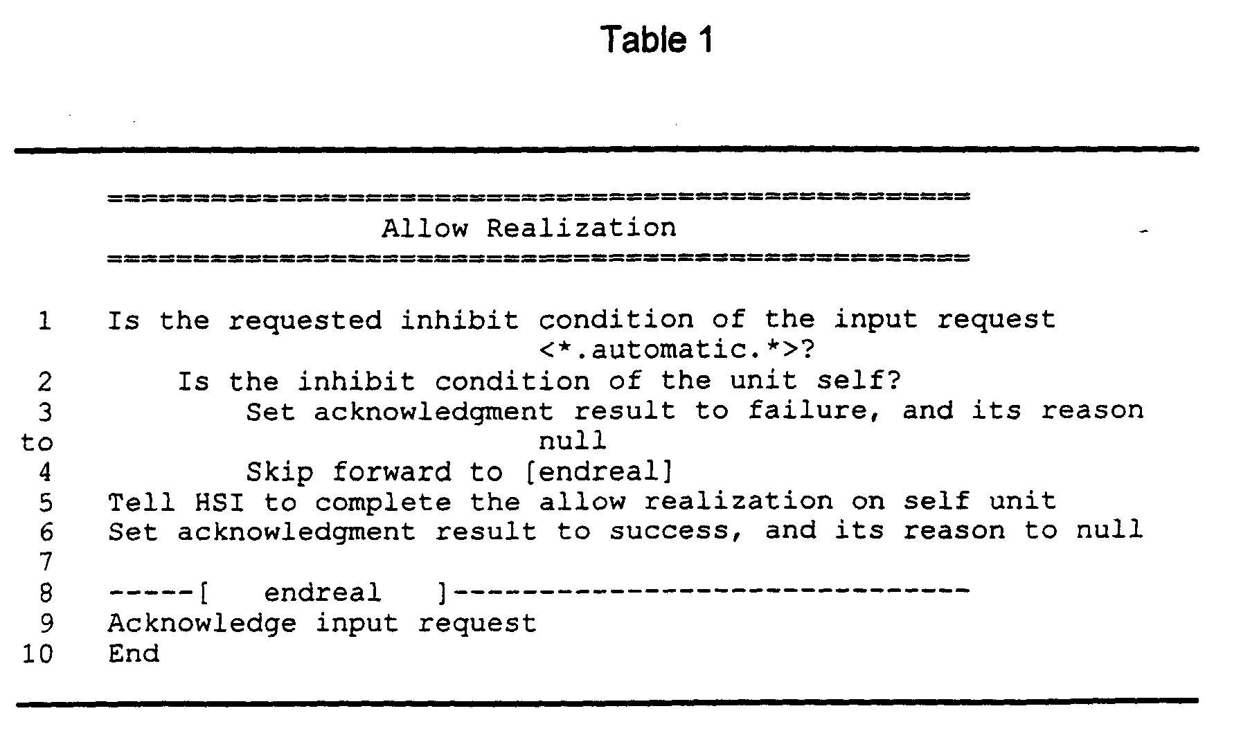
Table 1 is exemplary pseudo-code that describes steps that can be used in
this embodiment of the algorithm to effect the allow realization. In the
pseudo-code for this realization and in all other realization and validation
algorithms whose descriptions follow, the convention followed is that if a
statement is true or is answered in the affirmative, then processing
proceeds to next indented step. If the statement is false or is answered in
the negative, then processing proceeds to next statement at the same or
smaller indentation level of the first statement. Also, in the pseudo-code
below and in the pseudo-code for the other realizations and validations later
described, the word "unit" is used. In the context of this document, "unit" is
intended to be the equivalent of the word "component" as used both above
and below.
-
Referring now to Table 1, a determination is first made whether the
allow request is a request to put the inhibit state of the subject component
into a condition of
inhibited, with an
automatic secondary condition (line 1).
If it is not, the hardware-software interface (HSI) it told to allow interrupts for
that component (line 5), and the condition of the component is then
changed to allow interrupts. An acknowledgment result is set to success
(line 6) and an acknowledgment is sent back to the requester indicating the
successful realization result (line 9). If the
allow request is a request to put
the inhibit state of the subject component into a condition of
inhibited, with
an
automatic secondary condition, then a determination is made whether
the current
inhibit condition had previously been manually set (line 2). If it
had, the change will be not be allowed and the acknowledgment result is set
to
failure (line 3), and reported back to the requester with a
null reason dine
9).
-
As noted, the
de-elevate operation lowers an active component to
standby. Table 2 is exemplary pseudo-code that describes steps that can
be used in this embodiment of the algorithm to effect the
de-elevate
realization. First, success is assumed and the acknowledgment result is
initialized to success. The condition of the subject component is then set
(line 2) to the condition specified by the request. An
inhibit realization is
invoked to inhibit interrupt signals to all components that might receive them
from the subject component, i.e., those in the subject component's interrupt
PUG (line 3). An
inhibit realization is then invoked to inhibit interrupt signals
from the subject component that might affect the subject component itself
(line 4). A request is then sent (line 5), to the HSI to change the primary
condition of the subject component from
working to
ready. If the request
succeeds or is aborted (line 6), then a
refresh realization is invoked to
refresh all components related to this component by the switch PUG (i.e.,
they are checked to see that they have the correct condition) (line 7), and an
allow realization is invoked to again
allow interrupt signals from the subject
component (line 8). Processing continues (line 1) and an
allow realization is
invoked to
allow interrupt signals to all components in the subject
component's interrupt PUG and success is acknowledged (line 17). If the
invocation to
de-elevate fails (line 10), then the subject component is
removed (line 11) by invoking the
remove realization for this component,
and a fault detection and analysis (FDA) component (not shown) is informed
that the
de-elevate relation has failed (line 12). The acknowledgment result
is set to failure and its reason for failure being that that the de-elevate
operation on the component could not be performed (line 13). An
allow
realization then again allows interrupt signals to all components related to
the subject component by its interrupt PUG (line 16), and the failure is
reported to the requester (line 17).
-
The
elevate realization changes an out-ot-service standby
component to an active component. Table 3 is exemplary pseudo-code that
describes steps that can be used in this embodiment of the algorithm to
effect the
elevate realization. Firstly, an
inhibit realization inhibits interrupt
signals to all components that receive them from the subject component
(line 1) (i.e., those other components in the subject component's interrupt
PUG). Then an
inhibit realization inhibits interrupt signals within the subject
component itself (line 2). A request is then made to the HSI to
elevate the
primary condition of the component to
working (line 3). If that invocation
aborts, the component is left in its present condition and is not put into
service. An
allow realization then allows inhibit signals from the subject
component and an acknowledgment result is set to aborted with a reason
being the failure to elevate the component. (lines 4-6). An
allow realization
is then invoked to allow interrupt signals from the component's interrupt
PUG and the request is acknowledged to the requester (lines 19-20). If the
invocation to
elevate fails, then the component is malfunctioning and a
remove realization is invoked to remove the component from service (lines
8-9). The FDA is then informed of the failure so that "clean-up" can be
performed later, and the acknowledgment result is set to failure (line 10-11).
An
allow realization is then invoked to
allow interrupts to the component's
interrupt PUG and the request is acknowledged (lines 19-20). If the
invocation through the HSI to
elevate the component succeeds, then an
allow realization is invoked to allow interrupts from the component (line 13),
and a
refresh realization is invoked to refresh the condition of all
components in the subject component's switch PUG (line 14). The
condition of the subject component is then changed to the requested
condition (line 15), and an
allow realization is invoked to allow interrupts
from the subject component to components in its interrupt PUG (line 19) and
success is acknowledged to the requester (line 20).
-
The
inhibit realization changes the condition of a component so that
interrupt signals are not propagated from the subject component to other
components. Table 4 is exemplary pseudo-code that describes steps that
can be used in this embodiment of the algorithm to effect the
inhibit
realization. First, a check is performed to determine if the request is one to
change the condition of the component to
inhibited with an
automatic
secondary condition when the current condition of the component is
inhibited with a
manual secondary condition (lines 1-3). If true, the request
will not be satisfied since a system rule precludes changing the condition of
a component which has been manually set since that
manual setting needs
to be given precedence over a subsequent request. An error is thus
returned to the requester (
lines 4, 5 and 10). Otherwise, if not manually set,
a request is sent to the HSI to inhibit interrupt signals from the component
(line 6). The condition of the component is changed so that interrupt signals
are inhibited and success is acknowledged back to the requester (line 10).
-
The
refresh realization resynchronizes the system condition of a
component with its actual hardware condition. Table 5 is exemplary pseudo-code
that describes steps that can be used in this embodiment of the
algorithm to effect the
refresh realization. In this realization, the HSI is
simply told to complete the
refresh realization of the component, i.e., the
component is asked to re-read its own internal data structure (line 1). The
success of this realization is then reported to the requester (lines 2-3). This
realization cannot fail.
-
The remove realization is invoked by a the requester to take a
working or ready component out-of-service and make it a standby
component. This operation consists of both removing the subject
component itself from service, and removing all children components of that
subject component. Table 6 is exemplary pseudo-code that describes steps
that can be used in an embodiment of the algorithm to effect the remove
realization. Firstly, the CLIENT is informed that a remove realization of the
subject component is about to begin (line 1). The CLIENT is any software
running on the subject component, or running off the subject component
that is dependent upon the subject component and that has registered
interest as a CLIENT. Such CLIENT software that is dependent upon the
subject component needs to be informed before the component is shut
down to enable such software to perform clean-up operations before a
remove realization of the component is effected.
-
A determination is then made (line 2) whether the tertiary condition of
the input request is family of equipment. This step questions whether the
present remove operation is being performed as a result of the removal of a
parent or an ancestor of the current subject component. If it is, a
determination is made whether such parent component is working or ready
(line 3). If it is, the subject component (a child of that parent) does not have
to be removed since a remove realization of the parent did not succeed.
The operation is still treated as a success even though the subject
component was not removed and the acknowledgment result is set to
success (line 4). Processing of the remove realization then skips to the end
of realization subroutine (endreal) (lines 45-48), where the input request is
acknowledged (line 46) and the CLIENT is informed that the remove
realization is about to end (line 26). If the input request is a consequence of
a request to an ancestor (line 2 being true) but the condition of the subject
component is unready or unusable (line 6), then the subject component is
already out-of-service and removed. No further action is therefore required.
The acknowledgment result is then set to success (line 7) and the afore-noted
endreal subroutine is followed.
-
If the request to remove the subject component is not a consequence
of a request to remove a parent, then (at line 9) a determination is made
whether the subject component is active and in-service (working.null or
working.primary). If it is, a determination is made (lines 10-11) whether the
condition of a spare or mate component of the subject component is ready
or working.secondary to determine whether there is another standby
component is available to perform the functions of the subject component if
the subject component is removed (lines 10-11). If such a component is
found, then an elevate realization is invoked to elevate such a spare or mate
component (line 12). A determination is then made whether that elevate
realization was successful. If that realization aborts, the acknowledgment
result of the remove realization is set to abort with its reason being a failure
to elevate the spare or mate, and no further action is taken on the subject
component (lines 13-15). Processing then proceeds to the afore-noted
endreal subroutine (lines 45-46). Similarly, if the elevate realization of the
spare or mate component (line 12) fails, failure is acknowledged with a
reason being re-validate, to indicate that since a failure has occurred, a
check needs to be performed to ensure that the system is being left in a
valid configuration (lines 18-20). If no spare or mate component of the
subject component is found, or if the condition of an existent spare or mate
component is neither ready nor working.secondary, then a de-elevate
realization is invoked (line 21) to change the subject component from a
working condition to a standby condition (e.g., ready.null.null).
-
The invocation of a remove realization on a child component of the
subject component (line 22) follows, which is reached either following the
de-elevation realization of the current component, or if the condition of the
current component is neither working.null nor working.primary (line 9 being
false). Such a remove realization is invoked for each child component of
the subject component (line 22). Thus, the remove realization is invoked for
each such child of the subject component by following the above-described
steps beginning at line 1 and applying them to the child component.
Eventually a de-elevate realization (line 21) is invoked to de-elevate the self
component, which in this realization is the child of the original subject
component. The next step (line 22) then invokes a remove realization on
the child of the then current component, or the child of the child. Assuming,
arguendo, that there is no child of any child of the original subject
component, then no invocation of a remove realization takes place and the
following step (line 23) is processed. If in fact there is a child of a child of
the original subject component, then the afore-described steps are reiterated.
-
Assuming that there are no children of any child, then the step of
determining whether the invocation to remove the child of the child failed or
aborted (line 23) need not be made and the associated steps on lines 24-28
are skipped. Interrupt signals are then inhibited from the child to
components in its interrupt PUG (line 29) and then within the child itself (line
30). The HSI is then told to complete the remove realization of the child
(line 31). A determination is then made whether that invocation failed (line
32). If it failed, the acknowledgment result is set to failure with its reason
being the failure to remove the child (line 33). A determination is then made
whether the condition of a child of the subject child is family of equipment.
Since it has been assumed that there is no child of the child, the steps at
lines 35-36 are skipped. Interrupt signal are then allowed from the child
component and from the child to components in its interrupt PUG (lines 37-38)
and processing continues at the end of realization (endreal) subroutine
(lines 45-46). At the latter, the input request (to remove the child) is
acknowledged and the CLIENT (of the child) is informed that the remove
realization is about to end. If the invocation to the HSI to complete the
remove realization (line 31) does not fail, so that the child is successfully
removed, processing continues by setting the condition of the child to the
condition specified by the remove realization of the child (line 40). Interrupts
are then allowed from the child component to components in its interrupt
PUG (line 41). The acknowledgment is set to success with a null reason
and routine maintenance (RMTCE) is told that the remove realization of the
child is completed (line 43). The remove realization of the child is then
completed at the endreal subroutine (steps 45-48), by acknowledging the
request (to remove the child) and telling the CLIENT of the child that the
remove realization is about to end. The remove realization is then repeated
for each child of the original subject component.
-
Once invocation of the remove realization of each child component of
the original subject component has been completed, a determination is
made whether that invocation aborted or failed for any child component of
the original subject component (line 23). If it has, then the acknowledgment
result is set to failure with a reason being the failure to remove a child of the
subject component (line 24). If the tertiary condition of any child component
is family of equipment (line 25), then an update realization is invoked to
update the condition of that child component to the condition specified by
the remove realization (line 26) for clean-up purposes. Processing then
skips forward to the endreal subroutine steps (lines 45-48). If there was no
failure or aborting of the remove realization for any child, then the inhibit
realization is invoked on the original subject component to inhibit interrupts
from the original subject component to components in its interrupt PUG and
within the subject component itself (lines 29-30).
-
The subject component's HSI is then told to complete the remove
realization on itself (line 31). A determination is then made whether that
invocation failed (line 32). If it did, the acknowledgment result is set to
failure with a reason being the failure to remove the component itself (line
33). A determination is then made whether the tertiary condition of any child
is family of equipment (line 34). If it is, an update realization is invoked (line
35) to update the condition of each child to the condition specified by the
original remove realization request. An allow realizations is then invoked on
the original subject component to allow interrupts from the subject
component to components in its interrupt PUG (lines 37-38). Processing
then completes at the endreal subroutine (lines 45-48).
-
If the
remove realization via the HSI succeeds (line 31), then
processing continues (at line 40) and the condition of the original subject
component is set to the condition specified in the original
remove request.
Interrupt signals are then allowed from the original component to
components in its interrupt PUG (line 41). The acknowledgment result is
then set to success (line 42) and RMTCE is informed that the
remove
realization of the original subject component is complete (line 43). The
endreal subroutine (lines 45-48) then completes the
remove realization by
acknowledging the original input request and telling the CLIENT of the
original subject component that the
remove realization is about to end.
-
The
restart realization restarts a component to re-initialize the
condition of the component to the condition it was in when it was turned on.
Table 7 is exemplary pseudo-code that describes steps that can be used in
an embodiment of the algorithm to the effect the restart realization. First,
the acknowledgement result is set to success (line 1) and the
inhibit
realization is invoked on the component (line 2) to halt the propagation of
interrupt signals from the subject component. The HSI is then told to restart
the component, i.e., to re-set values in the component to their initial states
(line 4). If the attempt to restart via the HSI aborts (line 4), then likely there
is a fault in the subject component and the component needs to be removed
by invoking the
remove realization (line 5) on that component. The FDA is
then informed that the
restart realization of that component failed (even
though it only aborted) and the acknowledgment result is changed to
aborted, with a reason of null (lines 6 and 7). That result is then provided to
the requester (line 17). If the attempt to restart via the HSI fails (line 9), then
the component is removed (line 10) and the FDA is told that the
restart
realization has failed (line 11). The acknowledgment result is then changed
to failure (line 12) and the requester is informed of that result (line 17). If the
HSI operation succeeds, interrupt signals are allowed to again propagate
from the component by invoking the
allow realization (line 14). The
previously set acknowledgment result of success is then sent to the
requester (line 17).
-
The restore realization restores a non-working component to a
working condition. As an example, the restore realization restores an
unready component to a ready or working condition. Table 8 is exemplary
pseudo-code that describes steps that can be used in an embodiment of the
algorithm to effect the restore realization. The first step in the restore
realization determines whether the primary condition of a parent of the
subject component is unready (line 1). If the parent of the subject
component is unready, no attempt need be made to restore the subject
component to a higher condition. Thus, if the subject component's parent is
unready, the condition of subject component (primary, secondary and
tertiary) is set to the condition (primary, secondary and tertiary) of its
unready parent (line 2). The acknowledgment result is set to success (line
3) and the requester of the realization is acknowledged. If parent is not
unready, the CLIENT is told that the restore realization is about to begin so
that software that may be running can complete its current functioning (line
6). Interrupts are then inhibited from the subject component to components
in its interrupt PUG (line 7).
-
The HSI is then told to complete the restore realization on the subject
component to bring it to a ready condition (line 9). If that invocation fails
(line 10), the acknowledgment result is set to failure, with its reason being
the failure to restore the component. Processing then jumps to a failure
subroutine (fail) (lines 77-82). Upon failure, a remove realization is invoked
to remove the subject component (line 78). The fault detection and analysis
(FDA) is then informed that the restore realization of the subject component
has failed (line 79), and the input request is acknowledged as a failure (line
80). The CLIENT is then told that the restore realization is about to end
(line 81). The restore realization is then complete (line 82). If the invocation
to the HSI to complete the restore realization does not fail (line 9), then
processing continues by invoking an allow realization to allow interrupt
signals from the subject component to components in its interrupt PUG (line
13). The condition of the subject component is then set to the condition
specified in the original restore request (line 14). Interrupts are then allowed
from the subject component (line 15). An update realization is then invoked
to update the condition of the parent to the condition specified by the restore
request to make the parent's condition consistent with that of its child.
-
At this point, the component being restored is either in a ready
condition or a working.secondary condition. A determination is now made
whether the subject component is the type of component that should have
its children restored when it is in this type of condition (line 18). This is
determined by a parameter associated with the subject component's type
that is specified when the system as a whole is defined. If the subject
component is that type of component, then a restore realization is invoked
for each child of the subject component (line 21). Thus, the present restore
realization (starting at line 1) is invoked as it is applies to each child of the
subject component. The same processing steps previously applied to the
original subject component are now applied to the child. Thus, firstly, a
determination is made whether the primary condition of the parent of the
child is unready (line 1), where the parent of the child thus devolves back to
the original subject component. Since the condition of the subject
component is known not to be unready, processing continues with the
CLIENT of the child being told that the restore realization of the child is to
begin (line 6). The previously described steps are then processed as they
apply to the child, with the HSI being directed to complete the restore
realization of the child (line 9). Such invocation either succeeds or fails. If it
fails, the acknowledgment result is set to failure for the restore realization of
the child component (line 11). The steps within the fail subroutine (lines 77-82)
are then followed as they apply to the child, including invoking a remove
realization (line 78) of the child.
-
If the HSI succeeds in restoring the child, the previously described
steps (allowing interrupts from the child to components in its interrupt PUG,
setting the condition of child to a specified condition, and allowing interrupts
from within the child itself) (lines 13-15) are processed as applied to the
child component. The invocation of the update realization (line 16) is then
applied to the parent of the child, i.e., the subject component itself. A
determination is next made whether the children of the child should be
restored when condition of the child is ready.null or working.secondary (line
18). Since it has been assumed for purposes of the present discussion that
no child has a child, processing skips forward to the next step at that same
indent level.
-
A determination is then made whether the requested condition of the
child is ready. null or working.secondary (line 31). If it is, the restore
realization of the child has been effectively accomplished and processing
skips forward to the success subroutine (line 68-69). The acknowledgment
result for the child is then set to success (line 69). The end restore (endrst)
subroutine (lines 71-75) is then processed by telling routine maintenance
(RMTCE) that the restore realization for the child has been completed (line
72), acknowledging the input request as applied to the child (line 73), and
telling the child's CLIENT that the restore realization of the child is about to
end.
-
If, on the other hand, the requested condition of the child in neither
ready. null nor working.secondary (line 31), then an elevate realization is
invoked on the child (line 34) to bring the condition of the child to
working.null or working.primary. If that invocation to elevate fails (line 35),
the acknowledgment result is set to failure with its reason being the failure
to self elevate the child component (line 36). Processing next continues at
the endrst subroutine (lines 71-75), telling RMTCE that the restore
realization on the child has been completed, acknowledging the input
request (a failure to restore the child), and telling the child's CLIENT that the
restore realization is about to end. If the invocation to elevate does not fail,
but aborts (line 38), the acknowledgment result is set to aborted with the
reason being a failure to elevate the child. The steps in the previously noted
endrst subroutine are then followed. If the elevate realization succeeds,
then the child is placed into a working.null or working.primary condition.
-
A determination is then made whether the children of this component
should be restored when the condition of the component is working.null or
working.primary (line 41). Since the child has no children, processing
continues skips forward (to line 54) to determine whether the LUG maximum
availability check fails. This test determines whether too many components
of the same type are currently in service. If such checks do in fact fail, a
further determination is made whether a spare or mate to this child is in a
working.null or working.primary condition (line 55). If yes, a de-elevate
realization is invoked on such spare or mate to the child (line 57). If that de-elevate
realization fails (line 58), the acknowledgment result for the child is
set to failure with its reason being the failure to de-elevate a spare or mate
(line 59). Processing then skips forward to the endrst subroutine. Similarly,
a determination is made whether the de-elevate realization aborted (line
62). If yes, the acknowledgment result is set to aborted with its reason
being the failure to de-elevate a spare or mate (line 63). If the de-elevate
realization of the spare or mate neither failed nor aborted, then the de-elevate
realization succeeded (line 66), and processing continues at the
success subroutine (lines 68-69) to complete processing of the child there
and at the succeeding endrst subroutine (lines 71-75).
-
If the LUG maximum availability checks fails (line 54), but the
condition of the spare or mate component is neither working.null or
working.primary (line 55), success is assumed and processing of the child
continues at the success and endrest subroutines. Similarly, if the LUG
maximum availability checks did not fail (line 54), then success is assumed
and processing immediately proceeds to the success and endrst
subroutines. Once processing of a child of the original subject component is
completed, the same procedures are then followed for each other child of
that subject component being restored.
-
Once the restore realization has been invoked for each child of the
original subject component (line 21), a determination is made whether the
restore realization failed for any child (line 22). If it did, the acknowledgment
result is set to failure and the reason being a failure to restore all of the
children. Processing skips forward to the fail subroutine (lines 77-82),
applying that subroutine now to the original subject component. If the
restore realization did not fail for any child but aborted (line 26), then the
acknowledgment result is set to aborted with a reason being a failure to
restore all the children. Processing then moves to the endrst subroutine
(lines 71-75), applying its previously described steps to the original subject
component. If the restore realization of all the children neither fails nor
aborts, then it has succeeded and the condition of the original subject
component is set to that condition specified by the original restore request
(line 30). A determination is then made whether the condition of the input
request is ready.null or working.secondary (line 31). If it is, processing skips
to the success and endrst subroutines, thereby completing the restore
realization of the original subject component and its children.
-
If the condition of the input request is neither ready.null nor
working.secondary (line 31), then an elevate realization is invoked the for
the subject component (line 34). If that elevate realization fails (line 35), the
acknowledgment result is set to failure with the reason being the failure to
elevate the current component (line 39). Processing then continues at the
endrst subroutine. If that elevate realization aborts (line 38), the
acknowledgment result is set to aborted for the same reason.
-
If the elevate realization neither fails nor aborts, then it has
succeeded and processing continues to now determine whether the children
of the component should be restored when the condition of the component
is workng.null or working.primary (line 41). Since, to have reached this
point, the children have already been successfully restored, the answer
must be no. Processing then continues (line 54) by determining whether the
LUG maximum availability checks fail as applied to the original subject
component. If they do, then a determination is made whether the condition
of the spare or mate of the original subject component is working.null or
working.primary (line 55). If it is, the previously described steps on lines 57-66
are applied to the spare or mate, de-elevating such spare or mate of the
original subject component. Upon success of the latter operation, the
acknowledgment result of the original restore request is set to success-through
the success subroutine (line 68-69), and the endrst subroutine
(lines 71-75) to complete the restore realization. If the de-elevate realization
of the spare or mate fails or aborts, then the acknowledgment result is set to
failure or aborted, respectfully, and the endrst subroutine completes the
restore realization. If the condition of the spare or mate of the original
subject component is neither working.null nor working.primary, or if the LUG
maximum availability checks do not fail, then the success and endrst
subroutines are followed to successfully complete the restore realization.
-
It has heretofore been assumed that the children of the subject
component should affirmatively be restored when the component is
ready.null or
working.secondary (line 18). If the children should not be
restored, then processing continues by next determining whether the
requested condition for the restore realization of the original subject
component is
ready.null or
working.secondary (line 31). If yes, processing
skips to the success subroutine, and the restore realization is completed
without restoring any child of the subject component. If it isn't, then an
elevate realization is invoked on the subject component (line 34). If this
elevate realization does not fail or abort, then a determination is made
whether the children of the original subject component should be restored
when the subject component is
working.null or
working.primary (line 41). If
they should, a
restore realization is invoked for each child (line 44) in a
manner described above, starting at
line 1. If that invocation fails or aborts,
the fail or endrst subroutines are respectively followed. If each child is
successfully restored, then the condition of the original subject component is
set to the condition specified by the elevate request (line 53). As previously
described, the LUG maximum availability checks are performed (line 54),
which may invoke a
de-elevate realization of a spare or mate of the original
component. If the children of the original subject component should not be
restored when the component is
working.null or
working.primary (line 41),
then processing proceeds directly to the LUG maximum availability checks
(line 54) as described above for possible invocation of a
de-elevate
realization of a spare or mate of the original component.
-
The
resynchronize operation resynchronizes the recorded condition
of a component with its "true" hardware condition. It causes a component to
check its own internal data with respect to its condition and compare it with
the condition that the requester thinks the component is in. Table 9 is
exemplary pseudo-code that describes steps that can be used in this
embodiment of the algorithm to effect the
resynchronize realization. The
HSI is first told to resynchronize the component (line 1). Thus a condition
which the requester believes the component to be in is given to the HSI and
a check is performed to determine whether the component is actually in that
condition. If that invocation succeeds (line 3), the acknowledgment result is
set to success (line 3) and the condition of the component is set to the
condition specified by the
resynchronize realization (line 4). Processing
then skips forward to the end of realization (endreal) subroutine (line 13-16),
where the FDA is informed that the component has been resynchronized
(line 14), and the input request is acknowledged (line 15). If the invocation
to the HSI aborts (line 6), then the acknowledgment result is set to aborted
with its reason being a failure to resynchronize (line 7). Processing then
skips forward to the endreal subroutine and the FDA is told of the abort
result of the
resynchronize realization. If the invocation to the HSI fails (line
9), then the acknowledgment result is set to failure with its reason being a
failure to resynchronize (line 10). Processing concludes with the endreal
subroutine, the FDA being told of the failure of the
resynchronize realization.
-
The
switch realization is used to change the conditions of two
components that can perform the same functions within the system, one
component being
working (working.null or
working.primary) and one
component being a standby component
(ready.null or
working.secondary),
so that their roles are reversed. These two components must be mates or
spares. The switch realization is invoked on the
working component to
change its secondary condition to
secondary and to change the primary
condition of its mate or spare to
working. Table 10 is exemplary pseudo-code
that describes steps that can be used in this embodiment of the
algorithm to effect the
switch realization. The first step tells the CLIENT that
the
switch realization is about to begin (line 1). The acknowledgment result
is initialized by setting it to success (line 2). An
elevate realization is then
invoked on the spare or mate (usually a mate) (line 3) to change the
condition of the component that was not the primary one. A determination is
made whether that invocation succeeded (line 4). If it did (line 5), a
de-elevate
realization is invoked on the other component (line 5). Processing
then skips forward to the endreal subroutine (lines 14-17) where the input
request is acknowledged (line 15) and the CLIENT is informed that the
switch realization is about to end (line 16). If the
elevate realization aborts
(line 7), the acknowledgment result is changed to aborted with its reason
being a failure to elevate the spare or mate component (line 8). Processing
then concludes with the endreal subroutine, as described. If the
elevate
realization fails (line 11), then the acknowledgment result is set to failure
and its reason being re-validate (line 12), so that the configuration of the
system can be checked when the realization is completed. The realization
is then completed with the endreal subroutine.
-
The update operation is used to change the condition of a
component to a specified condition. Table 11 is exemplary pseudo-code that
describes steps that can be used in this embodiment of the algorithm to
effect the
update realization. The
update realization never fails. The
acknowledgment result is set to success (line 1) and the condition of the
component is set to the condition specified by the request (line 2). The
input request is then acknowledged (line 3).
-
Prior to the invocation of a realization operation, in the embodiment
of the present invention described herein, a validation check is performed to
determine whether that realization should in fact be invoked. Accompanying
every request is an associated validation level, which may be associated
with the requester who is making the request. In the specific embodiment of
the present invention, the validation level varies between one and six, with a
validation level of one requiring the lowest degree of validation and a
validation of six requiring the highest degree of validation. For every
request, based in part on that validation level and the current configuration
of the system, some validation procedure is performed to determine whether
in fact a realization of that request should be performed. For example, if a
request to invoke a remove realization on a component is invoked, a
remove validation is first invoked to determine whether a backup component
exists to perform the work of the component to be removed and whether
such backup component is in a condition to perform that work.
-
A validation procedure, depending upon the type of realization
request, may be either a trivial procedure that blankly authorizes the
realization to proceed, or may be a specific algorithm that is performed to
determine whether or not the request is authorized to proceed to a
realization. A validation either succeeds or fails. If it succeeds, the request
is allowed and the appropriate realization algorithm is then executed. If the
validation fails, the request is denied and no attempt is made to invoke the
associated realization. A reason why the request has been denied is then
reported back to the requester. Described herein below are six algorithms
associated with realization operations previously described which require
specific validation before a realization can be invoked. As will be described,
each algorithm consists of a series of steps. Within each algorithm, if at any
point an indication of invalidity is produced, further validity processing is
halted and a realization operation is not invoked. In the specific
embodiment of the invention, the realizations that do not have associated
validation algorithms have blanket authorization to directly proceed to a
realization algorithm without needing a prior successful validation.
-
The
allow validation is invoked prior to an
allow realization. The allow
operation, as previously noted, is a request to allow interrupt signals to
propagate from a component. Table 12 is an example of pseudo-code that
can be used for the
allow validation. The first step determines whether the
level of validation is one, requiring the lowest degree of checking (line 1). If
yes, the operation automatically succeeds and the acknowledgment result is
set to success (line 2). Processing then proceeds to the end of validation
(endval) subroutine (lines 12-14) where the input request is acknowledged
and whereupon the
allow realization is invoked. If the level of validation is
not one, then a determination is made whether the inhibit state of the
component has been manually set (line 4). If it has, then a determination is
made whether the primary condition of the component is
unready or
unusable. If it is, then interrupt signals should not be allowed to propagate,
and the acknowledgment result is set to failure with its reason to chkself,
indicating that the self condition did not allow it (line 6). The endval
subroutine then acknowledges the input request, precluding invocation of
the
allow realization. If the condition of the component is neither
unready or
unusable, then the acknowledgment result is set to success (line 8) and
processing concludes with the endval subroutine, permitting the
allow
realization to proceed. If the inhibit state was not manually set, then the
acknowledgment result is set to failure, preventing invocation of the
allow
realization (line 10). This prevents changing the inhibit state of a
component that might be in transition due to some other occurring
realization algorithm that could change the inhibit state of the component
during its processing.
-
The
refresh validation is performed prior to a
refresh realization,
which is a request to have the component check its own internal data to look
at its own condition. In general, such an operation will almost always be
allowed. Table 13 is an example of pseudo-code that can be used for the
refresh validation. The first step determines whether the primary condition
of the component is
working or
ready. If it is, the acknowledgment result is
set to success (line 2) and the input request is acknowledged, thereby
allowing the
refresh realization to proceed (line 7). If the condition of the
component is neither
working nor
ready, then it must be in an
unready or
unusable condition, which might imply that the component is malfunctioning.
In such a case, the component should not refresh itself since it might do so
incorrectly. Thus, the acknowledgment result is set to failure, precluding
invocation of the
refresh realization (line 4), with the reason being that the
condition of the component itself has been checked. It should be noted that
the
refresh validation is independent of the value of the validation level.
-
Before a remove realization is invoked to remove a component from
service, a remove validation is performed. As previously described, a
remove request is a request to take a working component out of service to a
ready or unready condition, or to whatever condition is specified in the
request. Table 14 is exemplary pseudo-code that can be used to effect the
remove validation. The first step determines whether the requested level of
validation is one (a request that requires the lowest degree of validation)
(line 1). If it is, nothing further is need be done in the validation processing,
and the acknowledgment result is set to success (line 2). Processing then
skips to the endval subroutine (lines 80-82), where the input request is
acknowledged and a remove realization is performed. If the requested level
of validation is not one, a determination is made whether the requested level
of validation is greater than or equal to six (six requiring the highest level of
validation) (line 4). In the embodiment herein, a validation level of six
implies that the component upon which the remove request is being made
has been acting in a suspicious manner, which has been noted by a
technician or fault detection circuitry, and that the remove request is being
performed to enable a diagnostic test to be performed on the component. If
it is, a determination is made whether a diagnostic test on the subject
component can in fact be performed. This, in turn, is determined by
whether or not the subject component has helper components (line 5). If
the subject component has no such helper components, then the
acknowledgment result is set to failure (line 7), since without a helper
component, a diagnostic test cannot be performed. Processing then skips
to the endval subroutine and the remove realization is not performed. If the
subject component has one or more helper components (line 6), the
processing skips forward to the helper subroutine (lines 10-17).
-
Within the helper subroutine, another validation is invoked
(validations only invoke validations and realizations only invoke
realizations). Specifically, for each helper component, a remove validation
is invoked, with a validation level of five (line 11). For each such validation,
a determination is made whether that invocation failed (line 12). If it fails,
then the acknowledgment result of the remove validation of the subject
component is set to failure for the reason of checking the helper (line 13).
Processing then skips to the endval subroutine. Thus, if the remove
validation for any helper component of the subject component fails, then the
validation of the subject component fails. Similarly, if the remove validation
for any helper component aborts (line 15), the acknowledgment result is set
to aborted (line 16), thereby aborting the remove validation of the subject
component.
-
If the remove validation for each helper component succeeds (from
line 11), or if the requested level of validation is less than six (but greater
than one) (from line 4), a determination is made whether the request is a
descendent of an original request (line 18). In other words, a determination
is made whether the present request is an original validation request or is
the descendent of some other validation request. If it is a descendent, a
determination is made whether the primary condition of the parent of the
subject component is working or ready (line 19). If it is, the
acknowledgment result is set to success (line 20) since this is a "healthy"
state for the component to be in, and the remove realization can likely
proceed with implied impunity. Processing then skips forward to the endval
subroutine (line 21).
-
If the primary condition parent of the subject component is neither
working nor ready (line 19), or if the request is not a descendent of an
original request (line 18) but is an original request, then a determination is
made whether the tertiary condition of the component is either diagnostic or
interdiag (line 22). These conditions are indicative that the component is in
a diagnostic state and that a negative event has occurred. A determination
is then made whether the requested level of validation is greater than or
equal to three (line 24). If it is, the acknowledgment result is set to failure
(line 25) and processing skips to the endval subroutine (line 26), and the
remove realization is precluded. If the requested level of validation is not
greater than or equal or three (and greater than one), or, in other words,
equal to two, then the acknowledgment result is set to success (line 27) and
processing skips to the endval subroutine (line 26), allowing the remove
realization to proceed.
-
If the subject component is not in a diagnostic condition (line 22
being false), processing then determines whether the tertiary condition of
the component is in a pwralarm or pwroff condition (line 29), neither of
which are "good" conditions to be in. If it is in either such condition, a
determination is made whether the level of validation is six (line 30). If it is,
then the acknowledgment result is set to succeed (line 31), since it is known
that a diagnostic test is going to be performed. If the level of validation is
less than six, however, then the acknowledgment result is set to failure (line
33) with a reason that the power has been checked (chkpwr), since in a
power-off condition, one cannot do anything with the component.
-
If the tertiary condition of the component is neither pwralarm nor
pwroff (line 29), then a determination is made whether the secondary
condition of the component is growth (line 35), i.e. it is in some state where
the component is warming up. If it is, the acknowledgment result is set to
success (line 36), since the likelihood of a deleterious effect on the system
is small and the remove realization of the component can proceed. If the
secondary condition is not growth, a determination is made whether the
primary condition of the component is unusable, i.e., truly not working (line
38). If it is, a determination is made whether the requested level of
validation is greater than or equal to six (i.e., a diagnostic test is going to be
performed on the component) (line 39). If it is, then the acknowledgment-result
is set to success and the remove realization can proceed (line 40). If
the requested level of validation is less than six (but greater than one), the
acknowledgment result is set to failure and the remove realization is not
invoked (line 42).
-
A sequence of tests are then performed, the failure of any one of
which will cause the failure of the validation. The first test determines
whether the tertiary condition of the component is maintiprog (line 44). This
condition is indicative that some kind of routine testing is presently in
progress, and a component in such a testing condition would not be
interrupted for its removal. The next test determines whether the tertiary
condition of the component is campon (line 47). The campon condition is a
condition imposed on a working component while it awaits some other
event. A component would not be removed while it is in such a condition.
The next test determines whether the tertiary condition of the component is
update (line 50). The update condition is indicative that the system is in the
middle of updating another component's condition, which will have an effect
on the subject component. Again, a component would not be removed
while it is in this update condition.
-
If the component does not fail any of these previously described
tests, a determination is made whether the primary condition of the
component is unready (line 53). Since that is the condition that the
component should be in when it is removed, the acknowledgment result is
set to success (line 54) and processing concludes at the endval subroutine,
allowing the remove realization to proceed.
-
If the previous steps have neither resulted in the success or failure of
the remove validation, a determination is made whether the requested level
of validation is greater than or equal to five (line 56). This implies that much
is presently ongoing. A determination is then made whether the condition of
a spare or mate to the subject component is either working or ready (line
57) in order to ascertain that some spare or mate is available to assume the
functions of the subject component should the subject component be
removed. A determination is then made whether the condition of the spare
or mate is invalid for elevate (line 58), i.e., whether the spare or mate cannot
be elevated. If it cannot, the acknowledgment result is set to failure (line
59). If it is not invalid, then processing continues with respect to that spare
or mate in the spare subroutine (lines 66-78) to determine whether, by
changing the condition of the spare or mate, other problems will be created.
-
Within the spare subroutine, a determination is made whether the
LUG minimum availability check fails (line 68) to determine that the
minimum number of components of that subject component's type will be
working. If there will not be enough working components, the
acknowledgment result is set to failure to prevent the removal of the subject
component. If the LUG minimum availability check passes, a remove
validation of each child (if such child exists) of the subject component is
invoked (line 70). If the remove validation for any of the children fails (line
71), then a determination is made whether the reason for the failure was a
power condition (line 72). If it is, the acknowledgment result is set to failure
for the reason of failing to be able to remove the child. If the reason is not a
power condition, but some other reason, then processing is allowed to
continue. A determination is then made whether the LUG functionality
checks succeed (line 75). These tests are special set of checks associated
with the connectivity between components to determine whether the remove
operation will put the system into an undesirable configuration. If these
tests are passed, the acknowledgment result is set to success (line 76) and
processing concludes at the endval subroutine. If these tests fail, the
acknowledgment results is set to failure.
-
If the requested level of validation is less than five (but greater than
one) (line 56), processing skips directly to the spare subroutine for the
above-described tests. If the requested level of validation is greater than or
equal to five, but the condition of the spare or mate in neither
working nor
ready (line 57), then the spare or mate will not be able to elevated, and the
acknowledgment result is set to failure (line 63).
-
The
restart validation is performed prior to a
restart validation, which
is an operation that places a component into the initial condition that it was
in when it was first powered on. Table 15 is an example of pseudo-code
that can be used for the
restart validation. The first step determines
whether the primary condition of the component is
working or
ready (line 1).
If it is, the acknowledgment result is set to success (line 2) and the input
request is acknowledged (line 7), thereby allowing the
restart realization to
commence. If the primary condition of the component is neither
working nor
ready, then it is
unusable or
unready. It may then be in a condition where
attempting to restart it might cause even further damage. The
acknowledgment result is thus set to failure (line 4) and the input request is
acknowledged, precluding the
restart realization from being invoked.
-
The restore validation is performed prior to a restore validation, which
is invoked to bring a component back into service. Such a component may
have been idling as a standby component and the requester by this request
wants to bring the component back into service as a working component, or
to restore it as a ready component. Table 16 is an example of pseudo-code
that can be used for the restore validation. The first step determines
whether the primary condition of the component is unready (line 1). If it is,
then a determination is made whether the secondary condition of the
component is growth. The latter means that the component is one that is
going through an initialization phase between the time when a component is
first powered on and it is available for use (line 2). If it is, a determination is
made whether the requested condition of the request is ready.growth (line
3). That means the component should be moved up to the ready condition
but it still is in the growth stage. If it is, processing skips to the growth check
(growchk) subroutine (lines 8-13). In that subroutine a determination is
made there whether the present request is a descendent of an original
request (i.e., the present validation request is triggered as a result of trying
to validate a request on another component) (line 9).
-
If it is, a determination is made whether the tertiary condition of the
present component is family of equipment (the present component is having
its condition changed because a parent of this component had its condition
changed) (line 10). If it is, processing continues at the descendent check
subroutine (decendchk) (lines 15-20). Herein, the condition of such a parent
component is checked to determine whether it is in a condition that is invalid
for restore, i.e., is it in a condition from which one cannot automatically
restore a component (line 16). If it is, then the acknowledgment result is set
to failure since a component will not be restored if its parent cannot be
restored (line 17). The input request is then acknowledged as a failure and
the restore realization is not invoked. If the parent can be restored, then the
acknowledgment result is set to success (line 19) and the restore realization
is allowed.
-
If the condition of the component is not
family of equipment (line 10),
then the component is independent of its parent, and the acknowledgment
result is set to failure (line 12). That is, since it is known that the component
is in a
growth condition, but a descendent of another validation request, this
component should not be automatically restored without a direct request to
do so. If the requested condition of the input request is not
ready.growth
(line 3), the acknowledgment result is set to failure for reason that
chkgrowth failed (line 5) since a component can only go from
unready.growth to
ready.growth. If the condition of the component is not
unready (line 1), the acknowledgment result is set to failure (line 21) since
one can only restore a component from an
unready condition. Similarly, if
the primary condition of the component is
unready (line 1), but the
secondary condition of the component is not
growth (line 2), processing
skips to the growchk subroutine. The previously described steps within that
subroutine are then processed. If the request is not a descendant of an
original request (line 9), the processing jumps to the decendchk subroutine
(lines 15-20). If the condition of its parent component is not invalid-for-restore
(or if there is no parent component), then the acknowledgment result
is set to success (line 19), and the
restore realization is allowed.
-
The
switch validation is performed prior to a
switch realization, which
is invoked to change the conditions of a pair of components, one
working
and one standby so that the
working component becomes standby and the
standby component becomes
working. The request is made to the
working
component and affects both the
working component and its spare or mate.
Table 17 is an example of pseudo-code that can be used for the
switch
validation. The first step determines whether the condition of the
component is
working.secondary, ready, unready or unusable, all of which
are conditions that a component can be in if it is not
working.primary (line 1).
If it is, the acknowledgment result is set to failure with a reason chkself (line
2) since the
switch request can only be made on a component that is
working.primary. The input request is then acknowledged in the endval
subroutine (lines 17-19) and no
switch realization is performed. If the
component is
working.primary, a determination is then made whether the
condition of the spare or mate component is
working.secondary or
ready
(lines 5-6). If it is either, a determination is made whether the requested
level of validation is greater than or equal to five (five or six). If it is, a
determination is made whether the condition of the spare or mate
component is invalid to make the switch (line 8). If so, the acknowledgment
result is set to failure (line 9). If the spare or mate is not in an invalid state,
then processing is forwarded (line 11) to the spare subroutine (lines 15-19).
A determination is then made whether the LUG functionality checks have
succeeded. (line 16) As previously discussed, the LUG functionality checks
determine whether there are the correct number of components
working.primary in a logical unit group if the switch is effected. If such
check have succeeded, the acknowledgment result is set to success (line
17). If they have not, the acknowledgment result is set to failure (line 19). If
the requested level of validation is less than five (line 7), processing skips to
the spare subroutine since this is indicative of a more urgent request and
the operation will be performed regardless of the condition of the spare or
mate. Again, the LUG functionality checks determine whether the
acknowledgment result is set to success or failure. If the condition of the
spare or mate is neither
working.secondary nor
ready (line 5), then the
acknowledgment result is set to failure (line 12).
-
FIG. 2 is a flowchart that summarizes the steps associated the
above-described embodiment of the present invention. After starting, at
step 201, the configuration controller is initialized by providing the type of
each component in the system, and the relationships that exist between
components in the system. In addition, any special relationships or
conditions associated with any component are inputted, as, for example, a
component being invalid for restore. At step 202, a request is received to
change the condition of one or more components, where that request is
from a fixed predetermined set of possible request types. Accompanying
that request is a validation level which may be a function of the identity of
the requester as well as a condition that the subject component of the
request that the requester wants that component to have. At step 203, the
request is validated as a function of the request type and validation level.
As previously discussed, such validation may involve a specific algorithm
associated with the request type, which determines the success, failure, or
aborting of the validation processing. Alternatively, depending on the
request type, the validation may be a blanket authorization to proceed
regardless of where the request is originating. At step 204, a determination
is made whether or not the validation succeeded. If it did not, at step 205, a
report of the denial of the request is provided to the requester as well as a
reason for the denial. The configuration controller then awaits the receipt of
another request to change the condition of one or more components. If, at
step 204, the validation is determined to have succeeded or if, for the
particular request, there was a blanket authorization, then the realization
associated with the request type is performed, at step 206, using the
algorithm associated with that request type. That realization may succeed,
abort or fail. If the realization succeeds, then the condition of the subject
component is changed to the condition specified with the request. If it
aborts or fails, then the condition of the subject component is not changed
to the requested condition. At step 207, the result of the realization is
provided to the requester together with additional information, such as the
reason for the success, failure or abortion of the request. Processing then
returns to await receipt from of a next request to change the condition of
one or more components.
-
In the embodiment of the invention described above, requests are
validated using a validation algorithm associated with the type of request
before they are subsequently realized using a separate realization algorithm
associated with that same request type. It should be well understood by
one skilled in the art that the validation algorithms associated with the
request types could be incorporated into and made part of their associated
realization algorithms. Furthermore, it should be understood that the
present invention could be implemented in an embodiment that dispenses
with validation processing altogether, and incorporating only the realization
of each request via an algorithm associated with the type of request from a
fixed set of possible request types.
-
The configuration controller of the present invention can be
implemented as software running on a processor to control either software
components running on a system or hardware components, or a
combination of hardware and software components. The configuration
controller can also be implemented in hardware to similarly control either
software components or hardware components, or a combination of
hardware or software components in a system.
-
As previously described, in order to initialize the configuration
controller, information regarding each component and the relationships that
exist between components in the system needs to be provided. With
reference again to FIG. 1, a graphical user interface (GUI) 110 displayed on
a client terminal 111 has been devised that enables the attributes of each
type of component 104-1 ― 104-N within the system 102 to be specified as
well as those relationships that exist between these components. This
information is then used by the configuration controller 101 to effect the
above-described validations and realizations upon a request to change the
condition of a component in the system to a specified condition. This GUI
provides an easy to use methodology for entering those component
attributes and specifying those interrelationships, while providing a visual
representation of those relationships to the system administrator, or
whoever is setting up and initializing the configuration controller.
Specifically, the system administrator interacts through the GUI 110 on
client terminal 111 with processor 112 to supply the component attributes
and component interrelationships, which information is stored in a database
113, which in turn is connected to the configuration controller 101. That
information is then available to the request manager 107, the validator 108
and the realizer 109 as needed to process input requests. The graphical
user interface is the subject of co-pending patent application, Serial No.
09/464,602, filed on even date hereof.
-
As will be described, the administrator, for example, first creates
representations of the components through the use of a palette of buttons
from which a button for each component type can be created. If a
component type has already been defined, and a button for that component
type has already been established on the palette, by clicking on that button
with a graphical pointing device 114, such as a mouse, connected to client
terminal 111, an instance of that component type is created on the drawing
area of the GUI. If a component of that particular type has not already been
created, then a component of that type is created through a series of steps.
Using a series of dialog boxes, through a list selection, the selection of a
radio button, or typed-in values, all the attributes for a component type are
specified. A button for that newly created component type is then created
on the palette to enable as many components of that type to be defined on
the viewing area of the GUI canvas window as may exist in the system.
Thus each component of each type in the system is represented by some
geometric shape (e.g., polygon, oval, etc) in the viewing area with as many
instances of each such component type that exist in the actual system.
Once all of the components of each type and each instance in the system
have been defined, the relationships between those components displayed
in the drawing area on the screen are established by selecting, through the
graphical pointer, such as through the click of a computer mouse, a
relationship type as, for example, the child relationship of one component to
its parent component. By then clicking on the parent component and
dragging the graphical pointer, such as the mouse, to its child component
on the screen, a line is drawn between the two components and
automatically labeled to indicate, for this example, the parent-child .
relationship. This creates in the processor 112, which is collecting all the
information provided through the GUI and storing it in database 113, the
relationship that exists between these components. This process is
repeated for all the relationships between components in the system.
-
The GUI, through the processor 112, also checks for relationships
that may be defined that cannot actually exist. For example, if component A
is defined as the parent of component B, B cannot thereafter be defined as
the parent of A. Thus, certain types of mistakes that might be made in
defining relationships can be prevented.
-
A first dialog box 301 for defining the attributes of a component type
that has not already been defined is shown in FIG. 3. The first attribute to
be filled in is a name in box 302 which, for example in FIG. 3, is Top. The
other relevant attributes that need to filled in include Maximum Units in box
303, which when filled in indicates how many components of this type can
be present in a valid configuration. In this example, "2" is typed in fill-in box
303. A list of binary attributes (yes or no) are then selected via sets of radio
buttons 304, 305, 306 and 307. The Inhibit State button set 304 selects
whether this particular component can have an inhibit state in its condition,
i.e., whether or not its interrupt signals can be controlled. If the No button is
selected, the condition of a component of the type Top will only consist of a
primary, secondary, and tertiary condition. The selection of the Routine
Maintenance button set 305 indicates whether or not a component of this
type will ever goes through a routine maintenance procedure. The selection
of the Soft Switch button set 306 indicates whether or not a backup
component of this type will be able to process all of the work the active
component is doing without the loss of the work being performed on this
active component. The Mate/Spare button set 307 is redundant to
information that is diagrammatically provided separately.
-
The dialog box in FIG. 4 includes an upper window 401 and a lower
window 402. In the upper window 401, the administrator is able to define all
the possible conditions (primary-secondary-tertiary) that a component of this
type can be in. This is effected by inputting, as shown, each such possible
condition. This information is inputted by the administrator based upon his
or her knowledge of the actual component and the subset of all possible
conditions that a component of this type can ever be in. In upper window
401, the listed conditions are those conditions for which components of the
type Top can have, and which are entered, line-by-line, by the administrator.
It should be apparent that the list of conditions is merely an example. The
lower window 402 defines from all possible actions that can be performed
on a component, a subset of those actions that can be performed on a
component of this type. In the specific embodiment, a list of all possible
actions is presented to the administrator and those specific actions that are
permissible are selected by the administrator. Alternatively, each such
action can be inputted by the administrator line-by-line. The qualifier
associated with each action is part of the validation level, indicating who is
requesting the action.
-
FIG. 5 illustrates a Helper dialog box 501 in which the administrator
defines the conditions that a component of this type (Top, for this illustrative
example) can be in when acting as a helper for a diagnostic for another
component (generally of another type).
-
FIG. 6 illustrates a dialog box 601 for Timer Values, where timing
values are provided in fill-in boxes 602 that are used to determine whether a
specified operation has failed to occur. The administrator inputs a timer
value in each fill-in box 602 for each noted operation. If such an operation
is called upon to be effected with respect to any component of type Top
within the system, and that operation fails to occur within the time-value
specified for that operation, then the presumption is that the operation has
failed. As previously described, the algorithm calling the invocation of that
operation then reports a failure of that operation.
-
The values inputted through dialog boxes in FIGS. 3-6 together
characterize the attributes of a component of the example Top. The
attributes of each other type of component in a system are similarly defined
through the input of values in these dialog boxes. Thus, in the example that
follows, components of type Middle and type Bottom are defined in a similar
manner. Once each type of component in the system is defined, each
instance of each type of component and the relationships between the
components in the actual system is graphically represented in a GUI canvas
window for the configuration controller.
-
FIG. 7 shows the palette window of different component types that is
used to create component instances on the GUI canvas screen. Buttons
702, 703 and 704, labeled Top, Middle, and Bottom, are component types
that have been defined using the dialog boxes in the manner previously
described. In order to create an instance of any one of those components,
the administrator first clicks his mouse on the associated button in the
palette and then clicks in the GUI canvas window where he wants to place
that component. Upon clicking in the window, a polygon or other geometric
shape representing the component appears in the canvas screen. Multiple
instances of component types are defined on the canvas screen in a similar
manner. By clicking on the New Unit button 705 on palette 701, the
administrator can define a new component type through the dialog boxes
described above in connection with FIGS. 3-6. When completed, a button
with that newly created component type appears on palette 701. The Copy
Unit button 706 enables the administrator to create a new type of
component that might be similar to an existing component type, but slightly
different with respect to some of its attributes. The Delete button 707
deletes one of the component types from the palette.
-
FIG. 8 shows a portion 801 of a GUI canvas window in which two
components of type Top (labeled Top-0 and Top-1) and one component of
type Middle (labeled Middle-0-0) have been created using the palette of
FIG. 7. In order to define relationships between components, a particular
relationship from among all the possible of the defined relationships is
selected from a menu 802 across the top of the canvas window by clicking
via the computer mouse on the appropriate relationship button. As noted in
FIG. 8, these relationship buttons are Child, Spare, Mate, Helper, SPUG
and IPUG, corresponding to the previously described component
relationships. For example, to establish a parent-child relationship between
two components, the administrator first clicks on the Child button in menu
802. The administrator then clicks on the component instance within
window 801 that represents, for example, the parent component, such as
the component of type Top that is labeled Top-0 in window 801. The
administrator then drags the mouse pointer to the child component in
window 801, such as the component of type Middle that is labeled Middle-0-0,
where it is released. As noted in FIG. 9, which shows a portion of the
window, a line is automatically drawn between these components and is
labeled with the selected relationship, which for this example is the parent-child
relationship. Further, that relationship is created between these two
components by processor 112 and stored in database 113.
-
The logical unit group (LUG) relationship is created between
component instances through a dialog window shown in FIG. 10. The
administrator names the particular LUG in fill-in window 1001 (e.g., Bgroup)
and then specifies in the Minimum Availability window 1002 the minimum
number of such components that need to be active (e.g., 1), and in the
Maximum Availability window 1003, the maximum number of components
that are to be active (e.g.,. 3) in any configuration. Each configuration can
have plurality of LUGs. Each LUG, when established through the dialog
window of FIG. 10 creates a LUG button in a palette (not shown) on the
canvas window screen, similar to the buttons 802. Once a LUG button is
created, that particular LUG relationship is established in the canvas
window by clicking the mouse on that LUG button, and then clicking on a
first component and dragging the mouse to a second component in that
LUG relationship. All the components with that same LUG relationship are
similarly defined
-
FIG. 11 is an example of a canvas window screen in which all the
relationships between components have been created as described above
and then visually displayed. As can be noted, Top-0 and Top-1 have a
mate relationship with each other, as do components Middle-0-0 and
Middle-0-1. A parent-child relationship exists between Top-0 and both
Middle-0-0 and Middle-0-1. A parent-child relationship also exists between
Top-1 and Middle-0-0 and Middle-0-1. A parent-child relationship also
exists between Middle-0-1 and Bottom-0-0, Bottom-0-1 and Bottom-0-2.
There is a spare relationship between Bottom-0-0 and Bottom-0-1, and
between Bottom-0-1 and Bottom-0-2. Middle-0-0 is also a helper to Top-0
and Middle-0-1 is a helper to Top-1. Top-1's SPUG includes Bottom-0-0-,
Bottom-0-1 and Bottom-0-2. Top-0's IPUG is Top-1, Middle-0-0's IPUG is
Middle-0-1. Bottom-0-0's IPUG is Middle-0-1, as is Bottom-0-1's and
Bottom-0-2's IPUG. The units in the LUG Bgroup include Bottom-0-0,
Bottom-0-1 and Bottom-0-2.
-
Advantageously, the afore-described GUI enables the attributes of
each component type within a system and the relationships between
components in the system to be specified. This information is stored by the
processor 112 in database 113 and associated with the configuration
controller is then used when a request for an action associated with any of
the components is called upon in the manner described above.
-
The foregoing merely illustrates the principles of the invention. It will
thus be appreciated that those skilled in the art will be able to devise various
arrangements which, although not explicitly described or shown herein,
embody the principles of the invention and are included within its spirit and
scope. Furthermore, all examples and conditional language recited herein
are principally intended expressly to be only for pedagogical purposes to aid
the reader in understanding the principles of the invention and the concepts
contributed by the inventors to furthering the art, and are to be construed as
being without limitation to such specifically recited examples and conditions.
Moreover, all statements herein reciting principles, aspects, and
embodiments of the invention, as well as specific examples thereof, are
intended to encompass both structural and functional equivalents thereof.
Additionally, it is intended that such equivalents include both currently
known equivalents as well as equivalents developed in the future, i.e., any
elements developed that perform the same function, regardless of structure.
-
Thus, for example, it will be appreciated by those skilled in the art
that the block diagrams herein represent conceptual views of illustrative
circuitry embodying the principles of the invention. Similarly, it will be
appreciated that any flow charts, flow diagrams, state transition diagrams,
pseudo-code, and the like represent various processes which may be
substantially represented in computer readable medium and so executed by
a computer or processor, whether or not such computer or processor is
explicitly shown.
-
The functions of the various elements shown in the FIGS., including
functional blocks labeled as "processors" may be provided through the use
of dedicated hardware as well as hardware capable of executing software in
association with appropriate software. When provided by a processor, the
functions may be provided by a single dedicated processor, by a single
shared processor, or by a plurality of individual processors, some of which
may be shared. Moreover, explicit use of the term "processor" or "controller'
should not be construed to refer exclusively to hardware capable of
executing software, and may implicitly include, without limitation, digital
signal processor (DSP) hardware, read-only memory (ROM) for storing
software, random access memory (RAM), and non-volatile storage. Other
hardware, conventional and/or custom, may also be included. Similarly, any
switches shown in the FIGS. are conceptual only. Their function may be
carried out through the operation of program logic, through dedicated logic,
through the interaction of program control and dedicated logic, or even
manually, the particular technique being selectable by the implementor as
more specifically understood from the context.
-
In the claims hereof any element expressed as a means for
performing a specified function is intended to encompass any way of
performing that function including, for example, a) a combination of circuit
elements which performs that function or b) software in any form, including,
therefore, firmware, microcode or the like, combined with appropriate
circuitry for executing that software to perform the function.