EP1116985A2 - Optical modulator and optical modulation method - Google Patents
Optical modulator and optical modulation method Download PDFInfo
- Publication number
- EP1116985A2 EP1116985A2 EP01100593A EP01100593A EP1116985A2 EP 1116985 A2 EP1116985 A2 EP 1116985A2 EP 01100593 A EP01100593 A EP 01100593A EP 01100593 A EP01100593 A EP 01100593A EP 1116985 A2 EP1116985 A2 EP 1116985A2
- Authority
- EP
- European Patent Office
- Prior art keywords
- analyzer
- single crystal
- optical
- microwave
- light
- Prior art date
- Legal status (The legal status is an assumption and is not a legal conclusion. Google has not performed a legal analysis and makes no representation as to the accuracy of the status listed.)
- Ceased
Links
Images


Classifications
-
- G—PHYSICS
- G02—OPTICS
- G02F—OPTICAL DEVICES OR ARRANGEMENTS FOR THE CONTROL OF LIGHT BY MODIFICATION OF THE OPTICAL PROPERTIES OF THE MEDIA OF THE ELEMENTS INVOLVED THEREIN; NON-LINEAR OPTICS; FREQUENCY-CHANGING OF LIGHT; OPTICAL LOGIC ELEMENTS; OPTICAL ANALOGUE/DIGITAL CONVERTERS
- G02F1/00—Devices or arrangements for the control of the intensity, colour, phase, polarisation or direction of light arriving from an independent light source, e.g. switching, gating or modulating; Non-linear optics
- G02F1/01—Devices or arrangements for the control of the intensity, colour, phase, polarisation or direction of light arriving from an independent light source, e.g. switching, gating or modulating; Non-linear optics for the control of the intensity, phase, polarisation or colour
- G02F1/09—Devices or arrangements for the control of the intensity, colour, phase, polarisation or direction of light arriving from an independent light source, e.g. switching, gating or modulating; Non-linear optics for the control of the intensity, phase, polarisation or colour based on magneto-optical elements, e.g. exhibiting Faraday effect
Definitions
- the present invention relates to an optical modulator and an optical modulation method, and more particularly, the present invention relates to an optical modulator and an optical modulation method for obtaining an optical intensity as a result of modulation by an alternating-current signal of several hundreds or lower megahertz.
- optical modulators have been configured such that light passes through a magnetic ferrite single crystal, such as an yttrium iron garnet (YIG), a thin-line transducer, a microstrip line, or other suitable element, microwaves are applied thereto, and the optical intensity is modulated by the microwaves.
- YIG yttrium iron garnet
- a thin-line transducer such as an yttrium iron garnet (YIG)
- YIG yttrium iron garnet
- microstrip line or other suitable element
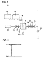
- FIG. 1 is a view showing an example of a conventional optical modulator that relates to the present invention described hereinbelow.
- An optical modulator 10 shown in FIG. 1 includes a plate-like magnetic garnet single crystal 12 for use as a magnetic ferrite single crystal.
- a microstrip line 14 defining a transducer is provided in a central portion of one of the primary surfaces of the magnetic garnet single crystal 12.
- An output terminal of a microwave-signal generator 16 is connected to one end of the microstrip line 14 via a microwave amplifier 18.
- an output terminal of an optional-signal generator 19 is connected to the microwave-signal generator 16.
- the optional-signal generator 19 modulates a microwave that has been output from the output terminal of the microwave-signal generator 16, and it uses an alternating-current signal having a frequency that is lower than that of the microwave for the modulation.
- the other end of the. microstrip line 14 is connected to a terminal resistor 20.
- a permanent magnet (not shown) is provided near the magnetic garnet single crystal 12.
- the permanent magnet is used to apply a dielectric-current magnetic field in a direction that is parallel to the magnetic garnet single crystal 12 and perpendicular to the microstrip line 14.
- a light source such as a laser-beam source 22, a polarizer 24, and a first lens 26 are arranged to be close to the magnetic garnet single crystal 12 in that order.
- the laser-beam source 22 generates leaser beams.
- the polarizer 24 linearly polarizes laser beams, which have been generated by the laser-beam source 22, in a predetermined direction.
- the first lens 26 concentrates the laser beams, which have been generated by the laser-beam source 22, into the magnetic garnet single crystal 12. In this way, the laser-beam source 22 is arranged such that laser beam emitted from the laser-beam source 22 is introduced to the magnetic garnet single crystal 12 and modulated by the microwave applied to the microstrip line 14.
- a second lens 28, an analyzer 30, a third lens 32, and a photodiode 34 are arranged to be spaced apart from the magnetic garnet single crystal 12 in that order and arranged to receive the light beam emitted from the magnetic garnet single crystal 12.
- the second lens 28 rectifies laser beams transmitted through the magnetic garnet single crystal 12 to parallel beams.
- the analyzer 30 allows the linearly polarized laser beams to be transmitted in a predetermined direction and the analyzer is arranged to have the crossed-Nicols relationship with the polarizer 24.
- the third lens 32 converges the laser beams transmitted through the analyzer 30.
- the photodiode 34 detects laser-beam signals.
- an output terminal of the photodiode 34 is connected to an input terminal of a photoelectric-current amplifier 36.
- optical systems (configurations of the magnetic garnet single crystal 12 and the components on two sides thereof) are substantially the same as a measurement optical system for transmission-type photomagnetic effects, such as a Faraday effect.
- a microwave is applied to the magnetic garnet single crystal 12 via the microstrip line 14 defining the transducer to couple the light and the microwave together in the magnetic garnet single crystal 12, and a polarized state of the light is modulated according to the microwave.
- the modulated state is then converted by a Faraday optical system into the variation in the intensity for the implementing detection.
- FIG. 2 is a view showing a waveform of an optical-signal that is produced without a microwave being applied in the optical modulator 10 shown in FIG. 1.
- FIG. 3 is a view showing a waveform of an optical-signal that is produced with a microwave being applied in the optical modulator 10 shown in FIG. 1.
- the microwave is not applied, as shown in FIG. 2, the light transmitted through the magnetic garnet single crystal 12 remains in the state of direct current, and the optical output is constant.
- the microwave is applied, as shown in FIG. 3, a modulated alternating-current component overlaps with a direct-current component.
- the microwave applied to the magnetic garnet single crystal 12 is preliminarily modulated according to the alternating-current signal, which has been generated by the optional-signal generator 19 and which has a frequency lower than that of the microwave. Therefore, the intensity of the light led to be incident on the photodiode 34 is also modulated further by the microwave modulated according to the low-frequency signal.
- the frequency band of each of the photoreceptor systems (such as the photodiode 34 and the photoelectric-current amplifier 36) includes the frequency of the signal that modulates the microwave and is lower than the frequency of the microwave, the individual photoreceptor system functions as a low-pass filter in which only the signal for modulating the microwave has sensitivity to the optical signal.
- the alternating-current component of the optical signal that is output from the photoelectric-current amplifier 36 matches the low-frequency signal that modulates the microwave.
- the optical-signal output is modulated according to the alternating-current signal having the frequency lower than the microwave.
- the reason that the microwave is first modulated using the low-frequency alternating-current signal and is then applied to the magnetic garnet single crystal 12 is that any frequency band other than the microwave frequency band cannot be propagated through the magnetic garnet single crystal 12.
- the microwave is just propagated therethrough, and optical modulation is implemented by the microwave.
- a sufficiently intensive external magnetic field is applied to the magnetic garnet single crystal 12
- a static magnetowave is excited, and optical modulation is implemented by the static magnetowave.
- preferred embodiments of the present invention provide an optical modulator optical and a modulation method in which the optical modulation amplitude is greatly increased and in addition the ratio S/N is greatly increased.
- an optical modulator includes a magnetic ferrite single crystal, an optical source, a photoreceptor system and an analyzer.
- the magnetic ferrite single crystal has a transducer mounted thereon and arranged to receive a microwave.
- the microwave is modulated by a signal having a frequency lower than the microwave.
- the optical source is arranged such that light emitted from the optical source is introduced to the magnetic garnet single crystal and modulated by the microwave applied to the transducer.
- the photoreceptor system is arranged so as to receive the modulated light that is emitted from the magnetic ferrite single crystal.
- the analyzer is provided between the magnetic ferrite single crystal and the photoreceptor system, and the analyzer is arranged such that a rotation angle of the analyzer about an optical axis thereof is shifted by an angle in the range of about 40 degrees to about 50 degrees from an extinct position at which an amount of direct-current light transmitted through the analyzer is minimized.
- a frequency band of a photoreceptor system includes, for example, the frequency of a signal that modulates the microwave, and concurrently, is lower than the frequency of the microwave.
- the magnetic ferrite single crystal is, for example, an iron yttrium garnet.
- An optical modulation method applies a microwave to a transducer formed in a magnetic ferrite single crystal and thereby modulates light being transmitted through the magnetic ferrite single crystal.
- the method is performed such that the microwave applied is modulated by an alternating-current signal having a frequency that is lower than that of the microwave, and the rotation angle of an analyzer in the optical-axis rotation direction is set by further rotating the analyzer by about 40 degrees to about 50 degrees from a rotation angle (extinct position) at which the amount of direct-current light transmitted through the analyzer is minimized.
- a frequency band of a photoreceptor system includes, for example, the frequency of a signal that modulates the microwave, and concurrently, is lower than the frequency of the microwave.
- the magnetic ferrite single crystal is, for example, an iron yttrium garnet.
- the rotation angle in the optical-axis rotation direction of the analyzer is set preferably by further rotating the analyzer by about 40 to about 50 degrees from a rotation angle (extinct position) at which the amount of direct-current light transmitted through the analyzer is minimized.
- the optical-modulation amplitude of an output from the first photoelectric-current amplifier 36 is 1 ⁇ V.
- preferred embodiments of the present invention achieve a significant advantage of increasing the optical-modulation amplitude to about 10 mV.
- FIG. 1 is a view showing an example of a conventional optical modulator that relates to the present invention.
- FIG. 2 is a view showing a waveform of an optical signal that is output without a microwave being applied in the optical modulator shown in FIG. 1.
- FIG. 3 is a view showing a waveform of an optical signal that is output with a microwave being applied in the optical modulator shown in FIG. 1.
- FIG. 4 is an extracted view of only an optical-system portion of the optical modulator shown in FIG. 1.
- FIG. 5 is a view showing an example optical modulator that uses light transmitted through an analyzer, but also light reflected therefrom.
- FIG. 6 is a graph showing the magnitude of a direct-current component and the magnitude (optical-modulation amplitude) of an optical output signal detected when the analyzer is driven to rotate.
- FIG. 4 is an extracted view of only the optical-system portion of the optical modulator 10 shown in FIG. 1.
- An oscillation direction a (the oscillation direction of an electric field) of incident light IB that is caused to be incident on the magnetic garnet single-crystal 12 is determined according to the rotation angle in the optical-axis rotation direction of the polarizer 24.
- the oscillation direction a of the incident light IB can be determined according to the rotation angle in the optical-axis rotation direction of the laser.
- the oscillation direction a of the incident light IB may be appropriately determined, however, the angle is preferably arranged to cause the ellipticity of the light emanated from the magnetic garnet single-crystal 12 to be minimized as much as possible, and the optical-modulation amplitude thereof is increased.
- the oscillation direction a of the incident light IB is fixed in a certain direction.
- the variations are individually caused in the magnitude of a direct-current component DC and in the optical-modulation amplitude (the magnitude of an alternating-current component AC) according to the low-frequency signal that modulates the microwave.
- the magnitude of the direct-current component DC is minimized. That is, it is an extinct position. The magnitude is not reduced to be zero when the emanated light becomes the elliptically polarized light.
- the analyzer 30 when the analyzer 30 is rotated by a certain degree from the extinct position, the magnitude of the alternating-current component AC was discovered to be maximized.
- the angle is about 45 degrees, and generally, the angle ranges from about 40 degrees to about 50 degrees. Therefore, by setting the analyzer 30 in the optical-axis direction by further rotating it, typically by the angle of about 45 degrees, and generally by the angle of about 40 degrees to about 50 degrees, a greatly increased and very large amplitude modulated by the microwave is achieved and a very high ratio S/N is also obtained.
- an optical modulator and an optical modulation method that use only light transmitted through the analyzer 30 of the optical modulator 10 shown in FIG. 1 may be used as a measurement apparatus and a measurement method for Faraday effects.
- FIG. 5 is a view showing an example of an optical modulator of the aforementioned type.
- An optical modulator 11 shown in FIG. 5 is arranged to use also light reflected from the analyzer 30 in the optical modulator 10. Therefore, in comparison to the optical modulator 10 shown in FIG. 1, in the optical modulator 11 shown in FIG. 5, a fourth lens 40 and a second photodiode 42 are arranged so as be spaced apart from an analyzer 30 in that order in the direction which intersects with the direction along which a second lens 28, an analyzer 30, and a third lens 32 are aligned and which extends through the analyzer 30.
- the fourth lens 40 converges light reflected from the analyzer 30.
- the second photodiode 42 detects the light reflected from the analyzer 30.
- An output terminal of a second photodiode 42 is connected to an input terminal of a second photoelectric-current amplifier 44.
- Individual output terminals of a first photoelectric-current amplifier 36 and the second photoelectric-current amplifier 44 are connected to an input terminal of a signal-operating unit 46.
- An output of the first photoelectric-current amplifier 36 is represented by A
- an output of the second photoelectric-current amplifier 44 is represented by B.
- (A - B)/(A + B) is output from an output terminal of the signal-operating unit 46.
- the analyzer 30 is rotated typically by about 45 degrees or generally by about 40 to about 50 degrees from an extinct position of light transmitted through the analyzer 30 in the optical modulator 11 shown in FIG. 5.
- the individual magnitudes of the alternating-current component of the output A of the first photoelectric-current amplifier 36 and the alternating-current component of the output B of the second photoelectric-current amplifier 44 are maximized.
- the optical modulator 11 shown in FIG. 5 can achieve a ratio S/N that is even higher than in the case of the optical modulator 10 shown in FIG. 1.
- pure-YIG bulk single crystal grown in a floating zone method was used for the magnetic ferrite single crystal.
- the crystal was cut to have approximate dimensions of 5 mm ⁇ 5 mm ⁇ 0.8 mm, and each surface thereof was abraded so as to define a mirror surface.
- a semiconductor laser having a wavelength of about 1.3 ⁇ m was used as a light source, and the light was emanated from one of the surfaces each having the approximate dimensions of 5 mm ⁇ 0.8 mm and was caused to be incident on and to pass through the crystal.
- the direction along which the incident light oscillates was fixed so as to match the direction of a plate surface that is normal relative to the plate-like crystal.
- a microstrip line defining a transducer was arranged to cause the characteristic impedance to be 50 ⁇ .
- a 1.72 GHz microwave modulated according to an AM method with a sine wave having a frequency of about 5 kHz was applied to the microstrip line.
- the direction of the microstrip line was arranged to be substantially perpendicular to the light-forwarding direction. No external magnetic field was applied thereto.
- the magnitude of a direct-current component and the magnitude (optical-modulation amplitude) of an optical-signal output detected with an analyzer being rotated are shown in a graph in FIG. 6.
- the angle ⁇ p at which the direct-current component is maximized is approximately 90 degrees
- the angle ⁇ p at which the optical-modulation amplitude is maximized is about 40 degrees
- the differential angle from the extinct position in this case is about 40 degrees.
- a thin-film single crystal grown according to, for example, a liquid epitaxial method may be used.
Landscapes
- Physics & Mathematics (AREA)
- Nonlinear Science (AREA)
- Engineering & Computer Science (AREA)
- Power Engineering (AREA)
- General Physics & Mathematics (AREA)
- Optics & Photonics (AREA)
- Optical Modulation, Optical Deflection, Nonlinear Optics, Optical Demodulation, Optical Logic Elements (AREA)
- Non-Reversible Transmitting Devices (AREA)
Abstract
Description
Claims (17)
- An optical modulator (10; 11) comprising:a single crystal (12) having a transducer (14) mounted thereon and arranged to receive a microwave, the microwave being modulated by a signal having a frequency lower than the microwave;an optical source (22) arranged such that light emitted from the optical source (22) is introduced to the single crystal (12) and modulated by the microwave applied to the transducer (14);a photoreceptor system (34, 36; 42, 44, 46) arranged to receive the modulated light which is emitted from the single crystal (12);an analyzer (30) provided between the single crystal (12) and the photoreceptor system (34, 36; 42, 44, 46), the analyzer (30) being arranged such that a rotation angle of the analyzer (30) about an optical axis thereof is shifted by an angle (p) in the range of about 40 degrees to about 50 degrees from an extinct position at which an amount of direct-current light transmitted through the analyzer (30) is minimized.
- An optical modulator (10; 11) according to Claim 1, wherein the single crystal (12) is a magnetic ferrite single crystal.
- An optical modulator (10; 11) according to Claim 1, wherein the single crystal (12) is a magnetic garnet single crystal.
- An optical modulator (10; 11) according to Claim 1, wherein a frequency band of the photoreceptor system (34, 36; 42, 44, 46) includes the frequency of the signal that modulates the microwave, and is lower than the frequency of the microwave.
- An optical modulator (10; 11) according to Claim 1, wherein the single crystal (12) is an iron yttrium garnet.
- An optical modulator (10; 11) according to Claim 1, wherein the analyzer (30) is arranged such that the rotation angle of the analyzer (30) about the optical axis thereof is shifted by an angle of about 45 degrees from the extinct position.
- An optical modulator (10) according to Claim 1, wherein the analyzer (30) is arranged to receive and analyze only light that is transmitted through the analyzer (30).
- An optical modulator (11) according to Claim 1, wherein the analyzer (30) is arranged to receive and analyze light that is transmitted through the analyzer (30) and light that is reflected from the analyzer (30).
- An optical modulation method comprising the steps of:providing a single crystal (12) having a transducer (14) mounted thereon;transmitting light through the single crystal (12);applying a microwave to the transducer (14) on the single crystal (12) to modulate light being transmitted through the single crystal (12);modulating the microwave applied to the transducer (14) by an alternating-current signal having a frequency that is lower than that of the microwave;passing the modulated light through an analyzer (30); andarranging a rotation angle of the analyzer (30) in the optical-axis rotation direction by rotating the analyzer (30) by about 40 degrees to about 50 degrees from a rotation angle at which the amount of direct-current light transmitted through the analyzer (30) is minimized.
- An optical modulation method according to Claim 9, further comprising the step of providing a photoreceptor system (34, 36; 42, 44 46) to receive the modulated light that is emitted from the single crystal (12).
- An optical modulation method according to Claim 9, wherein the single crystal (12) is a magnetic ferrite single crystal.
- An optical modulation method according to Claim 9, wherein the single crystal (12) is a magnetic garnet single crystal.
- An optical modulation method according to Claim 9, wherein a frequency band of the photoreceptor system (34, 36; 42, 44, 46) includes the frequency of the signal that modulates the microwave and is lower than the frequency of the microwave.
- An optical modulation method according to Claim 9, wherein the single crystal (12) is an iron yttrium garnet.
- An optical modulation method according to Claim 9, wherein the step of rotating the analyzer (30) is performed such that the analyzer (30) is shifted by an angle (p) of about 45 degrees from the extinct position.
- An optical modulation method according to Claim 9, wherein the analyzer (30) is arranged to receive and analyze only light that is transmitted through the analyzer (30).
- An optical modulation method according to Claim 9, wherein the analyzer (30) is arranged to receive and analyze light that is transmitted through the analyzer (30) and light that is reflected from the analyzer (30).
Applications Claiming Priority (2)
| Application Number | Priority Date | Filing Date | Title |
|---|---|---|---|
| JP2000008000 | 2000-01-17 | ||
| JP2000008000A JP3582441B2 (en) | 2000-01-17 | 2000-01-17 | Optical modulator and optical modulation method |
Publications (2)
| Publication Number | Publication Date |
|---|---|
| EP1116985A2 true EP1116985A2 (en) | 2001-07-18 |
| EP1116985A3 EP1116985A3 (en) | 2003-08-27 |
Family
ID=18536344
Family Applications (1)
| Application Number | Title | Priority Date | Filing Date |
|---|---|---|---|
| EP01100593A Ceased EP1116985A3 (en) | 2000-01-17 | 2001-01-10 | Optical modulator and optical modulation method |
Country Status (3)
| Country | Link |
|---|---|
| US (1) | US6462857B2 (en) |
| EP (1) | EP1116985A3 (en) |
| JP (1) | JP3582441B2 (en) |
Families Citing this family (2)
| Publication number | Priority date | Publication date | Assignee | Title |
|---|---|---|---|---|
| JP5461094B2 (en) * | 2008-08-08 | 2014-04-02 | 株式会社半導体エネルギー研究所 | Photoelectric conversion device and electronic apparatus including the photoelectric conversion device |
| KR101042798B1 (en) | 2009-04-29 | 2011-06-20 | 창원대학교 산학협력단 | MFC system for magnetic domain observation |
Family Cites Families (4)
| Publication number | Priority date | Publication date | Assignee | Title |
|---|---|---|---|---|
| US4217036A (en) * | 1978-04-17 | 1980-08-12 | Itek Corporation | Acoustic-optic coherent modulator and detection system |
| US4683421A (en) * | 1985-03-29 | 1987-07-28 | Westinghouse Electric Corp. | Drift compensation technique for a magneto-optic current sensor |
| US4671621A (en) * | 1985-04-29 | 1987-06-09 | American Telephone And Telegraph Company, At&T Bell Laboratories | Optical systems with antireciprocal polarization rotators |
| JP3399351B2 (en) * | 1998-03-11 | 2003-04-21 | 株式会社村田製作所 | Optical signal processing device and optical signal processing method |
-
2000
- 2000-01-17 JP JP2000008000A patent/JP3582441B2/en not_active Expired - Fee Related
-
2001
- 2001-01-10 EP EP01100593A patent/EP1116985A3/en not_active Ceased
- 2001-01-17 US US09/761,316 patent/US6462857B2/en not_active Expired - Fee Related
Also Published As
| Publication number | Publication date |
|---|---|
| JP3582441B2 (en) | 2004-10-27 |
| EP1116985A3 (en) | 2003-08-27 |
| US6462857B2 (en) | 2002-10-08 |
| US20010008456A1 (en) | 2001-07-19 |
| JP2001201726A (en) | 2001-07-27 |
Similar Documents
| Publication | Publication Date | Title |
|---|---|---|
| US5739943A (en) | Polarization control unit | |
| EP0138452B1 (en) | Laser light source device | |
| JP2815509B2 (en) | Optical attenuator | |
| US4563646A (en) | Optical magnetometer using a laser coupled to a magneto-optical medium | |
| US4516073A (en) | Magnetometer probe using a thin-film magnetic material as a magneto-optic sensor | |
| WO1995002192A1 (en) | Electric field sensor | |
| EP0696739B1 (en) | Optical sensor | |
| US6927909B2 (en) | Integrated magneto-optical modulator with optical isolator, method of manufacturing the same and optical communication system using the same | |
| US6462857B2 (en) | Optical modulator and optical modulation method | |
| US5500729A (en) | Magneto-optical arrangement for laser radar | |
| US4027948A (en) | Low loss laser modulator | |
| US6661935B2 (en) | Optical signal processing apparatus and method | |
| US6646783B1 (en) | Light modulation device and filter device | |
| US4810065A (en) | High-frequency light polarization modulator device | |
| JPH04128715A (en) | Optical modulator | |
| JPH0961772A (en) | Polarization controller | |
| JP2001264716A (en) | Optical modulator and optical modulation method | |
| US3526854A (en) | Large band-width laser modulator | |
| JP3612557B2 (en) | Physical quantity measuring apparatus and physical quantity measuring method | |
| JP4330923B2 (en) | Optical isolator integrated magneto-optical modulator, method for manufacturing the same, and optical communication system using the optical isolator integrated magneto-optical modulator | |
| JPH0961771A (en) | Polarization scrambler | |
| JP3442629B2 (en) | Probe for optical near-field excited spin-polarized scanning tunneling microscope | |
| JP2001272639A (en) | Optical device | |
| RU2031423C1 (en) | Method of light modulation and device for its realization | |
| Isella et al. | A low cost modulation technique for magneto-optical measurements |
Legal Events
| Date | Code | Title | Description |
|---|---|---|---|
| PUAI | Public reference made under article 153(3) epc to a published international application that has entered the european phase |
Free format text: ORIGINAL CODE: 0009012 |
|
| 17P | Request for examination filed |
Effective date: 20010110 |
|
| AK | Designated contracting states |
Kind code of ref document: A2 Designated state(s): AT BE CH CY DE DK ES FI FR GB GR IE IT LI LU MC NL PT SE TR |
|
| AX | Request for extension of the european patent |
Free format text: AL;LT;LV;MK;RO;SI |
|
| PUAL | Search report despatched |
Free format text: ORIGINAL CODE: 0009013 |
|
| AK | Designated contracting states |
Designated state(s): AT BE CH CY DE DK ES FI FR GB GR IE IT LI LU MC NL PT SE TR |
|
| AX | Request for extension of the european patent |
Extension state: AL LT LV MK RO SI |
|
| AKX | Designation fees paid |
Designated state(s): DE FR GB |
|
| 17Q | First examination report despatched |
Effective date: 20050216 |
|
| RAP1 | Party data changed (applicant data changed or rights of an application transferred) |
Owner name: MURATA MANUFACTURING CO., LTD. |
|
| STAA | Information on the status of an ep patent application or granted ep patent |
Free format text: STATUS: THE APPLICATION HAS BEEN REFUSED |
|
| 18R | Application refused |
Effective date: 20070807 |