EP1116939A2 - Thermal type air flow sensor - Google Patents
Thermal type air flow sensor Download PDFInfo
- Publication number
- EP1116939A2 EP1116939A2 EP01100125A EP01100125A EP1116939A2 EP 1116939 A2 EP1116939 A2 EP 1116939A2 EP 01100125 A EP01100125 A EP 01100125A EP 01100125 A EP01100125 A EP 01100125A EP 1116939 A2 EP1116939 A2 EP 1116939A2
- Authority
- EP
- European Patent Office
- Prior art keywords
- air flow
- flow rate
- type air
- rate sensor
- thermal type
- Prior art date
- Legal status (The legal status is an assumption and is not a legal conclusion. Google has not performed a legal analysis and makes no representation as to the accuracy of the status listed.)
- Granted
Links
Images



Classifications
-
- G—PHYSICS
- G01—MEASURING; TESTING
- G01F—MEASURING VOLUME, VOLUME FLOW, MASS FLOW OR LIQUID LEVEL; METERING BY VOLUME
- G01F1/00—Measuring the volume flow or mass flow of fluid or fluent solid material wherein the fluid passes through a meter in a continuous flow
- G01F1/68—Measuring the volume flow or mass flow of fluid or fluent solid material wherein the fluid passes through a meter in a continuous flow by using thermal effects
-
- G—PHYSICS
- G01—MEASURING; TESTING
- G01F—MEASURING VOLUME, VOLUME FLOW, MASS FLOW OR LIQUID LEVEL; METERING BY VOLUME
- G01F1/00—Measuring the volume flow or mass flow of fluid or fluent solid material wherein the fluid passes through a meter in a continuous flow
- G01F1/68—Measuring the volume flow or mass flow of fluid or fluent solid material wherein the fluid passes through a meter in a continuous flow by using thermal effects
- G01F1/684—Structural arrangements; Mounting of elements, e.g. in relation to fluid flow
- G01F1/688—Structural arrangements; Mounting of elements, e.g. in relation to fluid flow using a particular type of heating, cooling or sensing element
- G01F1/69—Structural arrangements; Mounting of elements, e.g. in relation to fluid flow using a particular type of heating, cooling or sensing element of resistive type
- G01F1/692—Thin-film arrangements
-
- G—PHYSICS
- G01—MEASURING; TESTING
- G01F—MEASURING VOLUME, VOLUME FLOW, MASS FLOW OR LIQUID LEVEL; METERING BY VOLUME
- G01F1/00—Measuring the volume flow or mass flow of fluid or fluent solid material wherein the fluid passes through a meter in a continuous flow
- G01F1/68—Measuring the volume flow or mass flow of fluid or fluent solid material wherein the fluid passes through a meter in a continuous flow by using thermal effects
- G01F1/684—Structural arrangements; Mounting of elements, e.g. in relation to fluid flow
- G01F1/6845—Micromachined devices
-
- G—PHYSICS
- G01—MEASURING; TESTING
- G01F—MEASURING VOLUME, VOLUME FLOW, MASS FLOW OR LIQUID LEVEL; METERING BY VOLUME
- G01F1/00—Measuring the volume flow or mass flow of fluid or fluent solid material wherein the fluid passes through a meter in a continuous flow
- G01F1/68—Measuring the volume flow or mass flow of fluid or fluent solid material wherein the fluid passes through a meter in a continuous flow by using thermal effects
- G01F1/696—Circuits therefor, e.g. constant-current flow meters
- G01F1/698—Feedback or rebalancing circuits, e.g. self heated constant temperature flowmeters
Definitions
- the present invention relates to a thermal type air flow rate sensor and a detection element, and more particularly, to a thermal type air flow rate sensor suitable for measuring an intake air flow rate of an internal combustion engine.
- an air flow rate sensor for measuring an intake air flow rate is provided in an electronically controlled fuel injection system for an internal combustion engine of an automotive vehicle
- a thermal type sensor is a mainstream for capability of direct detection of mass air flow rate.
- an air flow rate sensor fabricated by a semiconductor micro-machining technology is attracting attention for capability of lowering of cost and driving at low power.
- thermal type air flow rate sensors employing the conventional semiconductor substrate have been disclosed in Japanese Patent No. 2880651 and Japanese Patent Application Laid-Open No.11-83850(1999) .
- polycrystalline silicon (poly-silicon) has been used as a heating resistor for advantage in heat-electric resistivity and material cost.
- consideration has not be given for temperature dependency of air temperature upon measuring an intake air flow rate, and thus, accuracy of flow rate measurement cannot be sufficient.
- a problem is encountered in mechanical strength or the like of an electric insulation film supporting the heating resistor.
- an air temperature measuring resistor is formed with polycrystalline silicon (poly-silicon) to consider temperature dependency of the air temperature.
- the heating resistor and the temperature measuring resistor are formed with polycrystalline silicon (poly-silicon) respectively having different impurity concentration, fabrication process becomes complicate and cost is high.
- the electric insulation film (diaphragm) formed with the heating resistor has to be constructed to achieve thermal insulation with the semiconductor substrate and to be thin in the extent of several microns in total thickness for making a thermal capacity smaller for enhancing response characteristics. Therefore, when the heating resistor repeats heating and cooling or when the air flow rate is increased, excessive stress is loaded on the electric insulation film to possibly cause breakage.
- an object of the present invention is to provide a low cost thermal type air flow rate sensor and a control system for an internal combustion engine solving the problem in the prior art and fabrication process of which is simplified.
- a thermal type air flow rate sensor formed with at least a heating resistor and a temperature measuring resistor on a semiconductor substrate via an electric insulation film
- a heating resistor and the temperature measuring resistor by forming the heating resistor and the temperature measuring resistor with an impurity doped silicon (Si) semiconductor thin film, and by performing high concentration doping process so that an electric resistivity ( ⁇ ) of the silicon (Si) semiconductor thin film is less than or equal to 8 x 10 -4 ⁇ cm, sensitivity in measurement can be improved for increasing of a temperature coefficient of resistance ( ⁇ ) of the heating resistor and the temperature measuring resistor. Also, since the heating resistor and the temperature measuring resistor can be realized with the same impurity concentration to permit simplification of the fabrication process and lower the cost.
- the silicon (Si) semiconductor thin film is processed for high concentration doping of phosphorous (P) as impurity for further increasing the temperature coefficient of resistance ( ⁇ ).
- the silicon (Si) semiconductor thin film has a polycrystallized structure from an amorphous structure through an impurity thermal diffusion process for further increasing the temperature coefficient of resistance ( ⁇ ).
- the silicon (Si) semiconductor thin film is enabled high concentration doping through an impurity thermal diffusion process at a temperature higher than or equal to 1050 °C for longer than or equal top 30 minutes.
- the semiconductor substrate has a cavity portion, and at least the heating resistor is formed on said cavity portion via an electric insulation film for providing sufficient heat insulation between the heating resistor and the semiconductor substrate to improve sensitivity of the thermal type air flow rate sensor.
- a low cost control system for an internal combustion engine controlling fuel injection amount can be provided.
- Fig. 1 is a plan view showing the first embodiment of a thermal type air flow rate sensor element 1 according to the present invention
- Fig. 2 is a section of the sensor element 1 taken along line A - A' of Fig. 1.
- the element 1 is constituted of a semiconductor substrate 2 of silicon or the like, a diaphragm 7 constructed with electric insulation film 12 (12a, 12b), an upstream side heating resistor 4a and a downstream side resistor 4b formed on the electric insulation film 12a, a temperature measuring resistor 5 detecting a temperature of the heating resistor, an air temperature measuring resistor 6 formed at a tip end portion of the substrate 2 for measuring an air temperature, terminal electrodes 10 (10a, 10b, 10c, 10d, 10e, 10f, 10g) for connecting a signal of the element 1 to external circuits, wiring connecting portion 9 (9a, 9b, 9c, 9d, 9e, 9f, 9g) for connecting respective resistors and terminal electrodes 10, and the electric insulation film 12b for protecting respective resistors.
- respective resistors 4a, 4b, 5, 6 are formed with silicon (Si) semiconductor thin film processed by impurity doping, and is formed by high concentration doping process so that the electric resistivity ( ⁇ ) of the silicon (Si) semiconductor thin film is less than or equal to 8 x 10 -4 ⁇ cm.
- the embodiment of the thermal type air flow rate sensor according to the present invention will perform the following operation.
- a pair of the upstream and downstream side heating resistors 4a and 4b are directly connected electrically.
- a junction (intermediate tap) D is connected to the terminal electrode 10f by a leading electrode 9f.
- a heating (indirect heat) current flows so that a temperature of the temperature measuring resistor 5 detecting temperatures of the heating resistors 4a and 4b can be made higher for a predetermined temperature than a temperature of the air temperature measuring resistor 6 indicative of temperature of an air flow 11.
- the heating resistors 4a and 4b indicate substantially the same temperature as the temperature of the temperature measuring resistor 5 when air flow is zero and no temperature difference is caused.
- the heating resistor 4a arranged on upstream side subjects to greater cooling effect by the air flow 11 than the heating resistor 4b arranged on the downstream side.
- the temperature of the upstream side heating resistor 4a becomes a lower value than that of the downstream side heating resistor 4b.
- the temperature of the downstream side heating resistor 4b becomes lower than the temperature of the upstream side heating resistor 4a.
- Fig. 3 is a section showing the embodiment of the thermal type air flow rate sensor installed the element 1 of Fig. 1.
- the thermal type air flow rate sensor is constructed with including the element 1, the supporting body 19 and an external circuit 20.
- the element 1 is arranged within an auxiliary passage 18 within the air intake passage 17.
- the external circuit 20 is electrically connected to the terminal electrode 10 of the sensor element 1 via the supporting body 19.
- the intake air flows in the direction shown by 11, and in certain condition of the internal combustion engine, the intake air flows in the opposite direction (reverse flow).
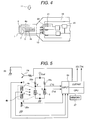
- Fig. 4 is an enlarged illustration of the element 1 and the supporting body 18 of Fig. 3.
- the element 1 is fixed on the supporting body 19.
- the terminal electrode 21 and the external circuit 20 formed with a signal processing circuit are fixed on the supporting body 19, in similar manner.
- the element 1 and the external circuit 20 are electrically connected by wire bonding of gold wire 22 or the like between the terminal electrodes 10 and 21, and thereafter, sealingly protected by the supporting body 19 (not shown) for protecting the gold wire 22, the electrode terminals 10, 21 and the external circuit 20 from upper side.
- Fig. 5 shows the resistors 4a, 4b 5, 6 of the element 1 of Fig. 1 and the external circuit 20 for signal processing.
- 23 denotes a power source
- 24 denotes transistor for applying the heating (indirect heating) current for the heating resistors 4a and 4b
- 25a, 25b, 25c are resistors
- 26 denotes a control circuit comprising an input circuit including an A/D converter or the like, an output circuit including a D/A converter or the like and CPU performing arithmetic process or the like
- 27 denotes a memory circuit.
- a voltage of terminals F, G of a bridge circuit consisted of the temperature measuring resistor 5, the air temperature measuring resistor 6, the resistors 25b, 25c, is input to the control circuit 26.
- ⁇ Th 150 °C
- the transistor 24 When the temperature of the temperature measuring resistor 5 is higher than the set temperature, the transistor 24 is controlled to be turned OFF and is controlled to be constant at the set value. At this time, the heating current value (corresponding to the charge E of the resistor 25a) applied to the heating resistors 4a, 4b becomes an air flow rate (Q).
- the direction of the air flow is detected by the temperature difference pf the heating resistors 4a, 4b.
- comparison of the temperature (resistance value) of the heating resistors 4a, 4b is performed by potentials at both ends of respective resistors connected in series.
- a potential difference between the points C and D of Fig. 5 corresponds to the temperature of the upstream side heating resistor 4a and a potential difference between the points D and E corresponds to the temperature of the downstream side heating resistor 4b. Accordingly, by inputting the potentials at the points C, D and E to the control circuit 26, the direction of the air flow is detected from the potential difference corresponding to respective heating resistors.
- Fig. 6(a) on the upper and lower surface of the silicon semiconductor substrate, about 0.5 micron thick of silicon dioxide (SiO 2 ) layers 12a and 15 are formed by thermal oxidation process.
- silicon dioxide SiO 2
- the electric insulation film 12a formed on the upper surface of the silicon semiconductor substrate 2 the material other than silicon dioxide can be used.
- silicon nitride Si 3 N 4
- slightly greater residual tensile stress than the silicon semiconductor substrate 2 may be used.
- amorphous silicon (Si) semiconductor thin film as the heating resistors 4a, 4b and the temperature measuring resistors 5 and 6, is formed in a thickness of about 1 micron by a method of CVD or so forth.
- the amorphous silicon (Si) semiconductor thin film is formed by a method of LPCVD using plasma, ECR-PCVD using electron cyclotron resonance, CVD using the micro wave and so forth.
- a forming temperature of the thin film to he lower than or equal to 600 °C, amorphous silicon (Si) semiconductor thin film can be obtained.
- impurity doping process is performed by thermal diffusion process for the formed amorphous silicon (Si) semiconductor thin film 13.
- a phosphate glass (POCl 3 ) is formed on the surface of the amorphous silicon (Si) semiconductor thin film 13, and heat treatment is performed at 1050 °C for 30 minutes to form the polycrystalline silicon (Si) semiconductor thin film 13, for which high concentration phosphorous (P) doping process is performed so that the electric resistivity is less than or equal to 8 x 10 -4 ⁇ cm, is formed.
- the amorphous film as the silicon (Si) semiconductor thin film 13 it is formed into polycrtal through thermal diffusion process.
- This process permits higher concentration phosphorous (P) doping process becomes possible in comparison with the case where the polycrystal is formed in advance and thermal diffusion is performed subsequently, for lowering electric resistivity ( ⁇ ), and in conjunction therewith, temperature coefficient of resistance ( ⁇ ) becomes large to have an appropriate material characteristics as resistor body.
- the semiconductor thin film 13 is patterned by a method, such as reactive ion etching or the like to form the heating resistors 4a, 4b, the temperature measuring resistor 5 and the air temperature measuring resistor 6 (not shown).
- a method such as reactive ion etching or the like to form the heating resistors 4a, 4b, the temperature measuring resistor 5 and the air temperature measuring resistor 6 (not shown).
- connecting terminal electrodes 10 (10a, 10b, 10c, 10d, 10e, 10f, 10g) and wiring connecting portions 9 (9a, 9b, 9c, 9d, 9f, 9g) for connecting each resistor and the terminal electrodes 10 are formed by aluminum, gold or the like.
- the electric insulation film 12b is formed in a thickness of about 0.5 microns in similar manner as the former electric insulation film 12a.
- a masking material 15 for etching is patterned into a predetermined shape to expose only etching portion of the semiconductor substrate 2.
- silicon dioxide or silicon nitride having higher etching selection ratio may be used.
- antistrophic etching is performed from the back surface of the silicon semiconductor substrate 2 using an etchant, such as potassium hydroxide (KOH) or the like for forming the cavity 8.
- an etchant such as potassium hydroxide (KOH) or the like for forming the cavity 8.
- P phosphorous
- N nitrogen
- Sb antimony
- As arsenic
- Al aluminum
- B Boron
- P (phosphorous) having high solid solubility at high temperature is optimal.
- the heating resistors 4a, 4b and the temperature measuring resistors 5, 6 with the doping-processed silicon (Si) semiconductor thin film, and by high concentration doping of phosphorous (P) so that the electric resistivity is less than or equal to 8 x 10 -4 ⁇ cm, the temperature coefficient of resistance ( ⁇ ) of the temperature measuring resistors 5, 6 can be maintained to be relatively large to improve temperature measuring sensitivity. Furthermore, by forming the heating resistors 4a, 4b and the temperature measuring resistors 5,6 with the silicon (Si) semiconductor thin film of the same impurity concentration, the silicon (Si) semiconductor thin films are formed simultaneously in a lump. Therefore, in comparison with Japanese Patent Application Laid-Open No. Heisei 11-83580, it becomes possible to provide the thermal type air flow rate sensor which is simplified the fabrication process and low cost.
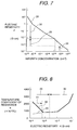
- Fig. 7 shows a relationship between the electric resistivity ( ⁇ ) of the silicon (Si) semiconductor thin film and the impurity concentration
- Fig. 8 shows a relationship between temperature coefficient of resistance ( ⁇ ) and electric resistivity ( ⁇ )
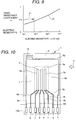
- Fig. 9 shows a relationship between a piezo resistance coefficient ( ⁇ ) and the electric resistivity ( ⁇ ).
- a region 29 where the impurity concentration shown in Figs. 7 and 8 is less than or equal to 3 x 10 19 (cm -3 ) is applied to the heating resistors 4a, 4b, and a region 30 where the impurity concentration is greater than or equal to 3 x 10 19 (cm -3 )is applied to the temperature measuring resistor 5.
- the reason is that a relationship between the temperature coefficient of resistance ( ⁇ ) and the electric resistivity ( ⁇ ) of the silicon (Si) semiconductor thin film shown in Fig. 8 is the relationship as shown by broken line 33 in the region doped at high concentration.
- the silicon (Si) semiconductor film shows a thermistor like resistance-temperature characteristics.
- metallic resistance-temperature characteristics is expressed by the expression (1).
- R R0 ( 1 + ⁇ (T - T0)) wherein R is a resistance value of the semiconductor film at temperature (T), R0 is a resistance value of the semiconductor film at temperature (T0) , and ⁇ is a temperature coefficient of resistance.
- the temperature measuring resistors 5, 6, it is desired for large variation of the resistance value with respect to the temperature for large temperature coefficient of resistance ( ⁇ ) to improve detection sensitivity. Accordingly, assuming the broken line 33 of Fig. 8, the relationship between the electric resistivity ( ⁇ ) and the temperature coefficient of resistance ( ⁇ ) becomes monotone increasing.
- the region 30 where temperature coefficient of resistance ( ⁇ ) is greater than or equal to 1000 (x 10 -6 /°C) (electric resistivity ( ⁇ ) is greater than or equal to 30 x 10 -4 ⁇ cm, and impurity concentration is less than or equal to 3 x 10 19 (cm -3 ) is selected.
- the same impurity concentration region 30 as the temperature measuring resistors 5, 6 may have too large electric resistivity ( ⁇ ).
- the resistance value of the heating resistors 4a, 4b become large to require high driving voltage to cause difficult for sufficiently heat. Accordingly, as the heating resistors 4a, 4b, a region where the impurity concentration shown by the region 29 of Fig. 8 is greater than or equal to 3 x 10 19 (cm -3 ) and the electric resistivity ( ⁇ ) is less than or equal to 30 x 10 04 ⁇ cm, is selected.
- the temperature measuring resistors 5, 6 and the heating resistors 4a, 4b are selected to have different impurity concentrations to make fabrication process complicate and make the cost high.
- piezo resistance coefficient ( ⁇ ) As shown by a relationship between piezo resistance coefficient ( ⁇ ) and the electric resistivity ( ⁇ ) shown in Fig. 9, according to increasing of impurity concentration (electric resistivity ( ⁇ ) becomes smaller), the piezo resistance coefficient ( ⁇ ) becomes smaller.
- the resistance variation ( ⁇ R/R) of the resistor is variable depending only on the temperature as shown in the expression (1) and the piezo resistance coefficient ( ⁇ ) as resistance variation factor other than the temperature is small.
- the piezo resistance coefficient ( ⁇ ) is large, stress in fabrication process in resistor and electric insulation film formation, etching and so forth causes aging to also vary resistance value (R) to make it impossible to accurately measure the air flow rate.
- the piezo resistance coefficient ( ⁇ ) can be made small. Therefore, in comparison with the fabrication process in Japanese Patent Application Laid-Open No. Heisei 11-83580 of prior application, stable air flow rate measurement becomes possible.
- Fig. 10 is a plan view of the second embodiment of the thermal type air flow rate sensor element 1 according to the present invention. What is different from the first embodiment of Fig. 1, the temperature measuring resistors 5a, 5b are formed upstream and downstream of the heating resistor 4.
- a region 31 where the electric resistivity ( ⁇ ) is less than or equal to 8 x 10 -4 ⁇ cm can be applied.
- the silicon (Si) semiconductor thin film having the same impurity concentration can be formed simultaneously in a lump, the thermal type air flow rate sensor with simplified fabrication process and low cost can be provided.
- thermo type air flow rate sensor constructed with the heating resistor and the temperature measuring resistor on the semiconductor substrate 2.
- the heating resistor and the temperature measuring resistor are formed with doped silicon (Si) semiconductor thin film, the high concentration doped region 31 of the electric resistivity ( ⁇ ) is less than or equal to 8 x 10 -4 ⁇ cm.
- the silicon (Si) semiconductor thin film having the same impurity concentration can be formed simultaneously in a lump, the thermal type air flow rate sensor with simplified fabrication process and low cost can be provided.
Landscapes
- Physics & Mathematics (AREA)
- Fluid Mechanics (AREA)
- General Physics & Mathematics (AREA)
- Measuring Volume Flow (AREA)
Abstract
Description
Claims (13)
- A thermal type air flow rate sensor (1) formed with at least a heating resistor (4a, 4b) and a temperature measuring resistor (5) on a semiconductor substrate (2) via an electric insulation film (12a), is characterized by said heating resistor (4a, 4b) and the temperature measuring resistor (5) are formed with an impurity doped silicon (Si) semiconductor thin film (13), and high concentration doping process being performed so that an electric resistivity (ρ) of the silicon (Si) semiconductor thin film (13) is less than or equal to 8 x 10⁻⁴ Ωcm.
- A thermal type air flow rate sensor (1) as set forth in claim 1, wherein said silicon (Si) semiconductor thin film (13) is processed for high concentration doping of phosphorous (P) as impurity.
- A thermal type air flow rate sensor ( 1 ) as set forth in claim 1 or 2, wherein said silicon (Si) semiconductor thin film (13) is a monocrystal.
- A thermal type air flow rate sensor (1) as set forth in claim 1 or 2, wherein said silicon (Si) semiconductor thin film (13) has a polycrystallized structure from an amorphous structure through an impurity thermal diffusion process.
- A thermal type air flow rate sensor ( 1 ) as set forth in any one of claims 1 to 4, wherein said silicon (Si) semiconductor thin film (13) is processed by high concentration doping through an impurity thermal diffusion process at a temperature higher than or equal to 1050 °C for longer than or equal to 30 minutes.
- A thermal type air flow rate sensor (1) as set forth in any one of claims 1 to 5, wherein said semiconductor substrate (2) has a cavity portion (8), and said heating resistor (4a, 4b) is formed on said cavity portion (8) via an electric insulation film (12a).
- A control system for an internal combustion engine measuring an intake air flow rate using a thermal type air flow rate sensor (1) as set forth in any one of claims 1 to 6, and controlling a fuel injection amount.
- A thermal type air flow rate sensor (1) including a resistor film provided on a semiconductor substrate (2) via an insulation film (12a) and generating a heat by power supply, and a control circuit controlling heat generation of said resistor film,
wherein a temperature coefficient of said resistor film is greater than or equal to 1000 x 10-6/°C and an electric resistivity is less than or equal to 8 x 10⁻⁴ Ωcm. - A thermal type air flow rate sensor (1) as set forth in claim 8, wherein said semiconductor substrate (2) is provided with a cavity portion (8).
- A thermal type air flow rate sensor (1) as set forth in claim 9, wherein said insulation film (12a) covers entire or part of said cavity portion (8).
- A detection element for a thermal type air flow rate sensor (1) comprising:a semiconductor substrate (2); anda resistor film provided on said semiconductor substrate (2) via an insulation film (12a) and a temperature coefficient of resistance greater than or equal to 1000 x 10-6/°C and an electric resistivity less than or equal to 8 x 10⁻⁴ Ωcm.
- A detection element for a thermal type air flow rate sensor (1) set forth in claim 11, wherein said semiconductor substrate (2) is formed with a cavity portion (8).
- A detection element for a thermal type air flow rate sensor (1) set forth in claim 12, wherein said insulation film (12a) covers entire or part of said cavity portion (8).
Applications Claiming Priority (2)
| Application Number | Priority Date | Filing Date | Title |
|---|---|---|---|
| JP2000010103A JP3468731B2 (en) | 2000-01-14 | 2000-01-14 | Thermal air flow sensor, element, and internal combustion engine controller |
| JP2000010103 | 2000-01-14 |
Publications (3)
| Publication Number | Publication Date |
|---|---|
| EP1116939A2 true EP1116939A2 (en) | 2001-07-18 |
| EP1116939A3 EP1116939A3 (en) | 2003-08-06 |
| EP1116939B1 EP1116939B1 (en) | 2009-04-15 |
Family
ID=18538154
Family Applications (1)
| Application Number | Title | Priority Date | Filing Date |
|---|---|---|---|
| EP01100125A Expired - Lifetime EP1116939B1 (en) | 2000-01-14 | 2001-01-12 | Thermal type air flow sensor |
Country Status (5)
| Country | Link |
|---|---|
| US (1) | US6490915B2 (en) |
| EP (1) | EP1116939B1 (en) |
| JP (1) | JP3468731B2 (en) |
| KR (1) | KR100728314B1 (en) |
| DE (1) | DE60138323D1 (en) |
Cited By (9)
| Publication number | Priority date | Publication date | Assignee | Title |
|---|---|---|---|---|
| FR2855260A1 (en) * | 2003-05-21 | 2004-11-26 | Bosch Gmbh Robert | Measurement element for a combustion engine air intake comprises an earth tap and five other taps together with associated heating resistances and temperature sensors |
| EP1348937A3 (en) * | 2002-03-27 | 2006-06-07 | Hitachi, Ltd. | Micromachined thermal mass flow sensor |
| EP1452838A3 (en) * | 2003-02-26 | 2007-05-09 | Hitachi, Ltd. | Thermal flow rate sensor |
| EP1703263A3 (en) * | 2005-03-15 | 2008-11-26 | Hitachi, Ltd. | Heating resistor flow sensor or acceleration sensor |
| US7755466B2 (en) | 2006-04-26 | 2010-07-13 | Honeywell International Inc. | Flip-chip flow sensor |
| US20130241017A1 (en) * | 2006-07-10 | 2013-09-19 | Renesas Electronics Corporation | Solid-state image pickup device |
| EP2740452A1 (en) | 2012-12-10 | 2014-06-11 | The Procter & Gamble Company | Absorbent article with high absorbent material content |
| EP2740450A1 (en) | 2012-12-10 | 2014-06-11 | The Procter & Gamble Company | Absorbent core with high superabsorbent material content |
| EP2740449A1 (en) | 2012-12-10 | 2014-06-11 | The Procter & Gamble Company | Absorbent article with high absorbent material content |
Families Citing this family (14)
| Publication number | Priority date | Publication date | Assignee | Title |
|---|---|---|---|---|
| JP4254263B2 (en) | 2002-08-22 | 2009-04-15 | 日産自動車株式会社 | Gas flow measuring device and gas flow measuring method |
| US6983653B2 (en) * | 2002-12-13 | 2006-01-10 | Denso Corporation | Flow sensor having thin film portion and method for manufacturing the same |
| DE10317466A1 (en) * | 2003-04-16 | 2004-12-09 | Robert Bosch Gmbh | electric motor |
| JP4839685B2 (en) * | 2005-06-13 | 2011-12-21 | 株式会社デンソー | Semiconductor device |
| JP4882732B2 (en) * | 2006-12-22 | 2012-02-22 | 株式会社デンソー | Semiconductor device |
| JP4497165B2 (en) | 2007-02-05 | 2010-07-07 | 株式会社デンソー | Manufacturing method of semiconductor device |
| US7500392B1 (en) | 2007-10-11 | 2009-03-10 | Memsys, Inc. | Solid state microanemometer device and method of fabrication |
| US20100078753A1 (en) * | 2008-10-01 | 2010-04-01 | Flowmems, Inc. | Flow Sensor and Method of Fabrication |
| US8263426B2 (en) * | 2008-12-03 | 2012-09-11 | Electronics And Telecommunications Research Institute | High-sensitivity z-axis vibration sensor and method of fabricating the same |
| JP5276964B2 (en) * | 2008-12-08 | 2013-08-28 | 日立オートモティブシステムズ株式会社 | Thermal fluid flow sensor and manufacturing method thereof |
| CN101980024B (en) * | 2010-09-29 | 2012-05-02 | 东南大学 | Rectangular platinum film two-dimensional wind speed and direction sensor |
| CN101980026B (en) * | 2010-09-29 | 2012-05-23 | 东南大学 | Two-dimensional wind speed and direction sensor for circular silicon film |
| JP5883740B2 (en) * | 2012-08-01 | 2016-03-15 | 日立オートモティブシステムズ株式会社 | Thermal air flow sensor |
| US10107662B2 (en) | 2015-01-30 | 2018-10-23 | Honeywell International Inc. | Sensor assembly |
Family Cites Families (13)
| Publication number | Priority date | Publication date | Assignee | Title |
|---|---|---|---|---|
| DE2728060A1 (en) * | 1977-06-22 | 1979-01-18 | Bosch Gmbh Robert | MEASURING PROBE WITH TEMPERATURE DEPENDENT RESISTANCE FOR QUANTITY MEASUREMENT |
| US4571996A (en) * | 1984-08-10 | 1986-02-25 | Allied Corporation | Air flow sensor |
| US4930347A (en) * | 1989-05-23 | 1990-06-05 | University Of Cincinnati | Solid state microanemometer with improved sensitivity and response time |
| JPH0760107B2 (en) * | 1989-07-11 | 1995-06-28 | 三菱電機株式会社 | Signal processing method for thermal flow sensor |
| US5237867A (en) * | 1990-06-29 | 1993-08-24 | Siemens Automotive L.P. | Thin-film air flow sensor using temperature-biasing resistive element |
| DE4426102C2 (en) * | 1994-07-22 | 1997-07-10 | Bosch Gmbh Robert | Sensor carrier for a device for measuring the mass of a flowing medium and method for producing a sensor carrier |
| JP2880651B2 (en) * | 1994-08-12 | 1999-04-12 | 東京瓦斯株式会社 | Thermal micro flow sensor and method of manufacturing the same |
| US5631417A (en) * | 1995-09-06 | 1997-05-20 | General Motors Corporation | Mass air flow sensor structure with bi-directional airflow incident on a sensing device at an angle |
| WO1997033161A1 (en) * | 1996-03-08 | 1997-09-12 | Holometrix, Inc. | Heat flow meter instruments |
| JP3333712B2 (en) * | 1997-06-19 | 2002-10-15 | 三菱電機株式会社 | Flow rate detecting element and flow rate sensor using the same |
| JP3364115B2 (en) * | 1997-07-03 | 2003-01-08 | 三菱電機株式会社 | Thermal flow detection element |
| JPH1183580A (en) | 1997-09-11 | 1999-03-26 | Hitachi Ltd | Thermal air flow sensor |
| JP3355127B2 (en) * | 1998-02-23 | 2002-12-09 | 株式会社日立製作所 | Thermal air flow sensor |
-
2000
- 2000-01-14 JP JP2000010103A patent/JP3468731B2/en not_active Expired - Fee Related
-
2001
- 2001-01-12 DE DE60138323T patent/DE60138323D1/en not_active Expired - Lifetime
- 2001-01-12 EP EP01100125A patent/EP1116939B1/en not_active Expired - Lifetime
- 2001-01-12 KR KR1020010001869A patent/KR100728314B1/en not_active Expired - Fee Related
- 2001-01-16 US US09/759,224 patent/US6490915B2/en not_active Expired - Lifetime
Cited By (11)
| Publication number | Priority date | Publication date | Assignee | Title |
|---|---|---|---|---|
| EP1348937A3 (en) * | 2002-03-27 | 2006-06-07 | Hitachi, Ltd. | Micromachined thermal mass flow sensor |
| EP2811265A1 (en) * | 2002-03-27 | 2014-12-10 | Hitachi, Ltd. | Micromachined thermal mass flow sensor and manufacturing method thereof |
| EP1452838A3 (en) * | 2003-02-26 | 2007-05-09 | Hitachi, Ltd. | Thermal flow rate sensor |
| FR2855260A1 (en) * | 2003-05-21 | 2004-11-26 | Bosch Gmbh Robert | Measurement element for a combustion engine air intake comprises an earth tap and five other taps together with associated heating resistances and temperature sensors |
| EP1703263A3 (en) * | 2005-03-15 | 2008-11-26 | Hitachi, Ltd. | Heating resistor flow sensor or acceleration sensor |
| US7555944B2 (en) | 2005-03-15 | 2009-07-07 | Hitachi, Ltd. | Physical quantity sensor |
| US7755466B2 (en) | 2006-04-26 | 2010-07-13 | Honeywell International Inc. | Flip-chip flow sensor |
| US20130241017A1 (en) * | 2006-07-10 | 2013-09-19 | Renesas Electronics Corporation | Solid-state image pickup device |
| EP2740452A1 (en) | 2012-12-10 | 2014-06-11 | The Procter & Gamble Company | Absorbent article with high absorbent material content |
| EP2740450A1 (en) | 2012-12-10 | 2014-06-11 | The Procter & Gamble Company | Absorbent core with high superabsorbent material content |
| EP2740449A1 (en) | 2012-12-10 | 2014-06-11 | The Procter & Gamble Company | Absorbent article with high absorbent material content |
Also Published As
| Publication number | Publication date |
|---|---|
| JP3468731B2 (en) | 2003-11-17 |
| DE60138323D1 (en) | 2009-05-28 |
| JP2001194202A (en) | 2001-07-19 |
| US6490915B2 (en) | 2002-12-10 |
| KR20010087155A (en) | 2001-09-15 |
| EP1116939A3 (en) | 2003-08-06 |
| EP1116939B1 (en) | 2009-04-15 |
| US20010015199A1 (en) | 2001-08-23 |
| KR100728314B1 (en) | 2007-06-13 |
Similar Documents
| Publication | Publication Date | Title |
|---|---|---|
| US6490915B2 (en) | Thermal type air flow sensor and control device for a vehicle | |
| JP3461469B2 (en) | Thermal air flow sensor and internal combustion engine controller | |
| EP1348937B1 (en) | Micromachined thermal mass flow sensor | |
| EP1643219B1 (en) | Thermal type fluid flow sensor | |
| JP5683192B2 (en) | Thermal flow sensor | |
| JP3355127B2 (en) | Thermal air flow sensor | |
| US9188470B2 (en) | Thermal flow meter | |
| CN100437043C (en) | Physical quantity sensor | |
| CN103380353B (en) | Thermal flowmeter | |
| EP1707925A1 (en) | Thermal flow meter | |
| CN101493349A (en) | Thermal type flow sensor | |
| JP4474771B2 (en) | Flow measuring device | |
| US6684693B2 (en) | Heat generation type flow sensor | |
| JP2001012985A (en) | Thermal air flow sensor and internal combustion engine controller | |
| JP2002048616A (en) | Thermal air flow sensor and internal combustion engine controller | |
| JPH11258021A (en) | Thermal air flow sensor | |
| JPH1183580A (en) | Thermal air flow sensor | |
| JP2002071416A (en) | Thermal air flow sensor and internal combustion engine controller | |
| JP2001021401A (en) | Thermal air flow meter | |
| JP2842485B2 (en) | Thermal flow sensor | |
| WO2017086086A1 (en) | Flow rate sensor | |
| KR20030026615A (en) | Mass flow sensor and mass flowmeter comprising the same | |
| JP2003075222A (en) | Gas flow meter and method of manufacturing the same |
Legal Events
| Date | Code | Title | Description |
|---|---|---|---|
| PUAI | Public reference made under article 153(3) epc to a published international application that has entered the european phase |
Free format text: ORIGINAL CODE: 0009012 |
|
| AK | Designated contracting states |
Kind code of ref document: A2 Designated state(s): AT BE CH CY DE DK ES FI FR GB GR IE IT LI LU MC NL PT SE TR |
|
| AX | Request for extension of the european patent |
Free format text: AL;LT;LV;MK;RO;SI |
|
| PUAL | Search report despatched |
Free format text: ORIGINAL CODE: 0009013 |
|
| AK | Designated contracting states |
Designated state(s): AT BE CH CY DE DK ES FI FR GB GR IE IT LI LU MC NL PT SE TR |
|
| AX | Request for extension of the european patent |
Extension state: AL LT LV MK RO SI |
|
| 17P | Request for examination filed |
Effective date: 20031007 |
|
| AKX | Designation fees paid |
Designated state(s): DE FR GB |
|
| 17Q | First examination report despatched |
Effective date: 20060822 |
|
| GRAP | Despatch of communication of intention to grant a patent |
Free format text: ORIGINAL CODE: EPIDOSNIGR1 |
|
| GRAS | Grant fee paid |
Free format text: ORIGINAL CODE: EPIDOSNIGR3 |
|
| RAP1 | Party data changed (applicant data changed or rights of an application transferred) |
Owner name: HITACHI, LTD. Owner name: HITACHI CAR ENGINEERING CO., LTD. |
|
| RIN1 | Information on inventor provided before grant (corrected) |
Inventor name: YAMADA, MASAMICHI Inventor name: NAKADA, KEIICHI Inventor name: WATANABE, IZUMI |
|
| GRAA | (expected) grant |
Free format text: ORIGINAL CODE: 0009210 |
|
| AK | Designated contracting states |
Kind code of ref document: B1 Designated state(s): DE FR GB |
|
| REG | Reference to a national code |
Ref country code: GB Ref legal event code: FG4D |
|
| REF | Corresponds to: |
Ref document number: 60138323 Country of ref document: DE Date of ref document: 20090528 Kind code of ref document: P |
|
| PLBE | No opposition filed within time limit |
Free format text: ORIGINAL CODE: 0009261 |
|
| STAA | Information on the status of an ep patent application or granted ep patent |
Free format text: STATUS: NO OPPOSITION FILED WITHIN TIME LIMIT |
|
| 26N | No opposition filed |
Effective date: 20100118 |
|
| PGFP | Annual fee paid to national office [announced via postgrant information from national office to epo] |
Ref country code: FR Payment date: 20130204 Year of fee payment: 13 Ref country code: GB Payment date: 20130109 Year of fee payment: 13 |
|
| GBPC | Gb: european patent ceased through non-payment of renewal fee |
Effective date: 20140112 |
|
| REG | Reference to a national code |
Ref country code: FR Ref legal event code: ST Effective date: 20140930 |
|
| PG25 | Lapsed in a contracting state [announced via postgrant information from national office to epo] |
Ref country code: FR Free format text: LAPSE BECAUSE OF NON-PAYMENT OF DUE FEES Effective date: 20140131 Ref country code: GB Free format text: LAPSE BECAUSE OF NON-PAYMENT OF DUE FEES Effective date: 20140112 |
|
| PGFP | Annual fee paid to national office [announced via postgrant information from national office to epo] |
Ref country code: DE Payment date: 20180103 Year of fee payment: 18 |
|
| REG | Reference to a national code |
Ref country code: DE Ref legal event code: R119 Ref document number: 60138323 Country of ref document: DE |
|
| PG25 | Lapsed in a contracting state [announced via postgrant information from national office to epo] |
Ref country code: DE Free format text: LAPSE BECAUSE OF NON-PAYMENT OF DUE FEES Effective date: 20190801 |