EP1116625A2 - Booster seat - Google Patents
Booster seat Download PDFInfo
- Publication number
- EP1116625A2 EP1116625A2 EP01100742A EP01100742A EP1116625A2 EP 1116625 A2 EP1116625 A2 EP 1116625A2 EP 01100742 A EP01100742 A EP 01100742A EP 01100742 A EP01100742 A EP 01100742A EP 1116625 A2 EP1116625 A2 EP 1116625A2
- Authority
- EP
- European Patent Office
- Prior art keywords
- seat member
- base
- seat
- support portion
- armrests
- Prior art date
- Legal status (The legal status is an assumption and is not a legal conclusion. Google has not performed a legal analysis and makes no representation as to the accuracy of the status listed.)
- Granted
Links
Images





Classifications
-
- B—PERFORMING OPERATIONS; TRANSPORTING
- B60—VEHICLES IN GENERAL
- B60N—SEATS SPECIALLY ADAPTED FOR VEHICLES; VEHICLE PASSENGER ACCOMMODATION NOT OTHERWISE PROVIDED FOR
- B60N2/00—Seats specially adapted for vehicles; Arrangement or mounting of seats in vehicles
- B60N2/02—Seats specially adapted for vehicles; Arrangement or mounting of seats in vehicles the seat or part thereof being movable, e.g. adjustable
- B60N2/04—Seats specially adapted for vehicles; Arrangement or mounting of seats in vehicles the seat or part thereof being movable, e.g. adjustable the whole seat being movable
- B60N2/16—Seats specially adapted for vehicles; Arrangement or mounting of seats in vehicles the seat or part thereof being movable, e.g. adjustable the whole seat being movable height-adjustable
-
- B—PERFORMING OPERATIONS; TRANSPORTING
- B60—VEHICLES IN GENERAL
- B60N—SEATS SPECIALLY ADAPTED FOR VEHICLES; VEHICLE PASSENGER ACCOMMODATION NOT OTHERWISE PROVIDED FOR
- B60N2/00—Seats specially adapted for vehicles; Arrangement or mounting of seats in vehicles
- B60N2/24—Seats specially adapted for vehicles; Arrangement or mounting of seats in vehicles for particular purposes or particular vehicles
- B60N2/26—Seats specially adapted for vehicles; Arrangement or mounting of seats in vehicles for particular purposes or particular vehicles for children
- B60N2/28—Seats readily mountable on, and dismountable from, existing seats or other parts of the vehicle
- B60N2/2857—Seats readily mountable on, and dismountable from, existing seats or other parts of the vehicle characterised by the peculiar orientation of the child
- B60N2/286—Seats readily mountable on, and dismountable from, existing seats or other parts of the vehicle characterised by the peculiar orientation of the child forward facing
-
- B—PERFORMING OPERATIONS; TRANSPORTING
- B60—VEHICLES IN GENERAL
- B60N—SEATS SPECIALLY ADAPTED FOR VEHICLES; VEHICLE PASSENGER ACCOMMODATION NOT OTHERWISE PROVIDED FOR
- B60N2/00—Seats specially adapted for vehicles; Arrangement or mounting of seats in vehicles
- B60N2/02—Seats specially adapted for vehicles; Arrangement or mounting of seats in vehicles the seat or part thereof being movable, e.g. adjustable
- B60N2/04—Seats specially adapted for vehicles; Arrangement or mounting of seats in vehicles the seat or part thereof being movable, e.g. adjustable the whole seat being movable
- B60N2/06—Seats specially adapted for vehicles; Arrangement or mounting of seats in vehicles the seat or part thereof being movable, e.g. adjustable the whole seat being movable slidable
- B60N2/062—Seats specially adapted for vehicles; Arrangement or mounting of seats in vehicles the seat or part thereof being movable, e.g. adjustable the whole seat being movable slidable transversally slidable
-
- B—PERFORMING OPERATIONS; TRANSPORTING
- B60—VEHICLES IN GENERAL
- B60N—SEATS SPECIALLY ADAPTED FOR VEHICLES; VEHICLE PASSENGER ACCOMMODATION NOT OTHERWISE PROVIDED FOR
- B60N2/00—Seats specially adapted for vehicles; Arrangement or mounting of seats in vehicles
- B60N2/02—Seats specially adapted for vehicles; Arrangement or mounting of seats in vehicles the seat or part thereof being movable, e.g. adjustable
- B60N2/04—Seats specially adapted for vehicles; Arrangement or mounting of seats in vehicles the seat or part thereof being movable, e.g. adjustable the whole seat being movable
- B60N2/16—Seats specially adapted for vehicles; Arrangement or mounting of seats in vehicles the seat or part thereof being movable, e.g. adjustable the whole seat being movable height-adjustable
- B60N2/1635—Seats specially adapted for vehicles; Arrangement or mounting of seats in vehicles the seat or part thereof being movable, e.g. adjustable the whole seat being movable height-adjustable characterised by the drive mechanism
- B60N2/165—Gear wheel driven mechanism
-
- B—PERFORMING OPERATIONS; TRANSPORTING
- B60—VEHICLES IN GENERAL
- B60N—SEATS SPECIALLY ADAPTED FOR VEHICLES; VEHICLE PASSENGER ACCOMMODATION NOT OTHERWISE PROVIDED FOR
- B60N2/00—Seats specially adapted for vehicles; Arrangement or mounting of seats in vehicles
- B60N2/02—Seats specially adapted for vehicles; Arrangement or mounting of seats in vehicles the seat or part thereof being movable, e.g. adjustable
- B60N2/04—Seats specially adapted for vehicles; Arrangement or mounting of seats in vehicles the seat or part thereof being movable, e.g. adjustable the whole seat being movable
- B60N2/16—Seats specially adapted for vehicles; Arrangement or mounting of seats in vehicles the seat or part thereof being movable, e.g. adjustable the whole seat being movable height-adjustable
- B60N2/169—Stepwise movement mechanisms, e.g. ratchets
-
- B—PERFORMING OPERATIONS; TRANSPORTING
- B60—VEHICLES IN GENERAL
- B60N—SEATS SPECIALLY ADAPTED FOR VEHICLES; VEHICLE PASSENGER ACCOMMODATION NOT OTHERWISE PROVIDED FOR
- B60N2/00—Seats specially adapted for vehicles; Arrangement or mounting of seats in vehicles
- B60N2/24—Seats specially adapted for vehicles; Arrangement or mounting of seats in vehicles for particular purposes or particular vehicles
- B60N2/26—Seats specially adapted for vehicles; Arrangement or mounting of seats in vehicles for particular purposes or particular vehicles for children
- B60N2/28—Seats readily mountable on, and dismountable from, existing seats or other parts of the vehicle
-
- B—PERFORMING OPERATIONS; TRANSPORTING
- B60—VEHICLES IN GENERAL
- B60N—SEATS SPECIALLY ADAPTED FOR VEHICLES; VEHICLE PASSENGER ACCOMMODATION NOT OTHERWISE PROVIDED FOR
- B60N2/00—Seats specially adapted for vehicles; Arrangement or mounting of seats in vehicles
- B60N2/75—Arm-rests
- B60N2/763—Arm-rests adjustable
- B60N2/77—Height adjustment
Definitions
- the present invention relates to a booster seat and, more specifically, to a booster seat having armrests and a seat member, which is capable of changing the distance between the armrests according to the height of the support portion of the seat member.
- a booster seat is used on a vehicle to seat a child taller than babies and shorter than adults, such as a schoolchild (hereinafter referred to simply as "child”), at a properly level on the seat of the vehicle.
- a schoolchild hereinafter referred to simply as "child”
- a seat belt cannot be properly put round a child if the child is seated on the seat of a vehicle. Therefore, a booster seat is placed on the seat of the vehicle and the child is seated on the booster seat so that the apparent height of the child is great enough to put the seat belt round the child.
- a known booster seat is provided with armrests that can be moved to adjust the width of the support portion of a seat member according to the build of a child to be seated on the booster seat.
- the height of the support portion remains unchanged regardless of the width thereof. Therefore the booster seat is narrow to a tall child and is unable to hold a short child steady.
- the present invention has been made in view of such a problem and it is therefore an object of the present invention to provide a booster seat having armrests and a seat member, which is capable of changing the distance between the armrests according to the height of the support portion of the seat member.
- a booster seat comprises a base to be mounted on a seat of a vehicle; a seat member placed on the base and having a support portion; a pair of armrests disposed on the opposite sides of the seat member, respectively; a seat height adjusting mechanism capable of vertically moving the seat member relative to the base to adjust the height of the support portion of the seat member, and an armrest adjusting mechanism capable of adjusting the distance between the armrests according to the vertical movement of the seat member by the seat height adjusting mechanism, wherein the distance between the armrests is decreased when the height of the support portion of the seat member is increased, and is increased when the height of the support portion of the seat member is decreased.
- the seat height adjusting mechanism comprises a plurality of wedge-shaped blocks disposed between the base and the seat member, tapered from the opposite sides of the support portion toward the middle of the support portion, respectively, and each having an upper surface serving as a first slope; and a bottom part of the seat member facing the plurality of wedge-shaped blocks and having a second slope corresponding to the first slopes; and the seat member can be moved vertically relative to the base by the cooperative action of the first slopes of the plurality of wedge-shaped blocks and the second slope of the seat member when the plurality of wedge-shaped blocks are moved in directions along the width of the support portion.
- the armrest adjusting mechanism includes a pair of side members extended along the opposite sides of the support portion of the seat member on the base, connected to the outer ends of the plurality of wedge-shaped blocks, respectively, and provided with the armrests, respectively; and the distance between the armrests can be adjusted by moving the side members together with the plurality of wedge-shaped blocks on the base in a direction along the width of the support portion.
- the seat height adjusting mechanism includes an operating bar provided with pins extending along the width of the support portion of the seat member; and the base and the seat member are provided with longitudinal slots capable of receiving the pins of the operating bar, respectively, and inclined relative to each other; and the seat member can be moved vertically relative to the base by the cooperative action of the pins of the operating bar and the slots of the base and the seat member when the operating bar is moved longitudinally on the base in a state where the seat member is able to move only vertically relative to the base.
- the armrest adjusting mechanism includes a pair of bearing portions formed on the base each for pivotally supporting one end of each armrest; the seat member is provided with a pair of openings in which the armrests are inserted, respectively; and the armrests turn in a plane perpendicular to a direction along the length of the support portion as the seat member is moved vertically relative to the base so that the distance between the armrests is adjusted.
- the seat height adjusting mechanism moves the seat member vertically relative to the base to adjust the height of the support portion of the seat member
- the armrest adjusting mechanism moves the armrests according to the vertical movement of the seat member by the seat height adjusting mechanism to adjust the distance between the armrests.
- the distance between the armrests can be automatically adjusted according to the adjustment of the height of the support portion of the seat member.
- the seat member when the seat member is moved vertically relative to the base by the cooperative action of the seat member and the plurality of wedge-shaped blocks capable of moving along the width of the support portion, and the distance between the armrests is adjusted by moving the pair of side members in coordination with the movement of the wedge-shaped blocks, the seat member can be vertically moved and the distance between the armrests can be adjusted by mechanical mechanisms.
- the booster seat is simple in construction and capable of functioning with reliability.
- the booster seat is simple in construction and capable of functioning with reliability.
- Figs. 1 to 3 show a booster seat in a first embodiment of the present invention.
- a booster seat 10 has a base 11 to be mounted on and fastened to a seat 51 of a vehicle, such as an automobile, a seat member 14 placed on the base 11 and having a support portion 14a for supporting a child thereon and armrests 12a and 13a disposed on the opposite sides of the support portion 14a of the seat member 14, respectively, to support the arms of the child seated on the seat member 14.
- the armrests 12a and 13a are formed on side members 12 and 13 extended on the opposite sides of the support portion 14a of the seat member 14 on the base 11, respectively.
- a plurality of tapered, wedge-shaped blocks 17 and 18 are arranged at equal intervals on the side members 12 and 13 so as to project from the inner side surfaces of the side members 12 and 13, respectively.
- the wedge-shaped blocks 17 and 18 extend from the side surfaces of the side members 12 and 13 toward a middle portion of the support portion 14a, respectively, i.e., toward each other.
- the wedge-shaped blocks 17 and the wedge-shaped blocks 18 are arranged alternately.
- the wedge-shaped blocks 17 and 18 have sloping upper surfaces 17a and 18a (first slopes), respectively.
- the seat member 14 is placed on the wedge-shaped blocks 17 and 18.
- a bottom portion of the seat member 14 facing the wedge-shaped blocks 17 and 18 has a V-shaped bottom surface (second slopes) 14b corresponding to the sloping upper surfaces 17a and 18a.
- the seat member 14 has a skirt 19 forming a front wall.
- Recesses 15 are formed in the side walls of the base 11.
- the wedge-shaped blocks 17 and 18 projecting from the side members 12 and 13 are inserted through the recesses 15 into the base 11.
- the base 11 has a guide surface 16 flush with the bottom surfaces of the recesses 15 and extending between the recesses 15.
- the side members 12 and 13 and the wedge-shaped blocks 17 and 18 are moved on the base 11 in directions along the width of the support portion 14a to raise and lower the seat member 14 relative to the base 11 by the cooperative action of the sloping upper surfaces 17a and 18a of the wedge-shaped blocks 17 and 18, and the bottom surface 14b of the seat member 14.
- the distance between the armrests 12a and 13a is adjusted by moving the side members 12 and 13 and the plurality of wedge-shaped blocks 17 and 18 on the base 11 in directions along the width of the support portion 14a.
- the wedge-shaped blocks 17 and 18 form a seat height adjusting mechanism that moves the seat member 14 vertically relative to the base 11 to adjust the height of the support portion 14a of the seat member 14.
- the side members 12 and 13 form an armrest adjusting mechanism that adjusts the distance between the armrests 12a and 13a in coordination with the vertical movement of the seat member 14 caused by the wedge-shaped blocks 17 and 18 having outer ends connected to the side members 12 and 13.
- the distance between the armrests 12a and 13a is decreased by the armrest adjusting mechanism when the height of the support portion 14a of the seat member 14 is increased by the seat height adjusting mechanism, and is increased by the armrest adjusting mechanism when the height of the support portion 14a of the seat member 14 is decreased by the seat height adjusting mechanism.
- Fig. 3A shows the booster seat 10 shown in Figs. 1 and 2 in a state where the armrests 12a and 13a are spaced a maximum distance W1 apart and the support portion 14a is at a minimum height H1.
- the booster seat 10 is provided with positioning members for preventing the longitudinal and lateral displacement of the seat member 14 to ensure the satisfactory operation of the booster seat 10.
- helical compression springs 21 are put on the bolts 20 to bias the seat member 14 toward the wedge-shaped blocks 17 and 18. The helical compression springs 21 prevent the seat member 14 effectively from rattling.
- the wedge-shaped blocks 17 and 18 are locked in place on the base 11 by a locking mechanism.
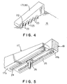
- a locking mechanism it is preferable to form a projection 22 on one side surface of each of the wedge-shaped blocks 17 and 18, and to form a plurality of projections 23 on the guide surface 16 of the base 11 at predetermined intervals to engage the projection 22 in a space between the adjacent projections 23 as shown in Fig. 4 to retain each of the wedge-shaped blocks 17 and 18 at a desired position.
- interlock the wedge-shaped block 17 projecting from one the side member 12 and the wedge-shaped block 18 projecting from the side member 13 and adjacent to the wedge-shaped block 17 by an interlocking mechanism.
- a booster seat in a second embodiment of the present invention will be described with reference to Figs. 6 to 9B.
- a booster seat 30 has a base 32 to be mounted on and fastened to a seat 51 of a vehicle, such as an automobile, a seat member 31 placed on the base 32 and having a support portion 31a for supporting a child thereon, armrests 33 disposed on the opposite sides of the support portion 31a of the seat member 31, respectively, to support the arms of the child seated on the seat member 31 and an operating bar 34 disposed between the base 32 and the seat member 31.
- FIG. 6 and 7 four box-shaped protrusions 35 having a rectangular sectional shape. Slots 36 are formed in the side walls of the box-shaped protrusions 35 so as to slope at an inclination to a direction along the length of the support portion 31a. Two openings 37 are formed in the support portion 31a of the seat member 31. The armrests 33 are passed through the openings 37.
- box-shaped cavities 38 are formed in the base 32 to receive the box-shaped protrusions 35 of the seat member 31, respectively.
- Substantially horizontal, longitudinal slots 39 are formed in side walls of the box-shaped cavities 38.
- the armrests 33 are provided at their lower ends with longitudinal shafts 40, respectively.
- the shafts 40 are parallel to the length of the support portion 31a and are fitted in bearing portions 43 (Fig. 6) formed in the base 32, such that the armrests 33 are able to turn on the shafts 40.
- the operating bar 34 is provided with four pins 41 laterally projecting from the side surfaces thereof in directions parallel to the width of the support portion 31a of the seat member 31.
- a handle 42 is formed in a front portion of the operating bar 34.
- the seat member 31 is put on the base 32 so as to cover the base 32 with the box-shaped protrusions 35 of the seat member 31 received in the box-shaped cavities 38 of the base 32, respectively.
- the operating bar 34 is inserted from the front side of the base 32 in a space between the seat member 31 and the base 32, and the pins 41 of the operating bar 34 are engaged in the slots 36 and 39 of the seat member 31 and the base 32, respectively.
- the shafts 40 of the armrests 33 extended through the openings 37 of the seat member 31 are fitted in the bearing portions 43 (Fig. 6) formed in the base 32.
- the seat member 31 is able to move only vertically because the box-shaped protrusions 35 are fitted in the box-shaped cavities 38.
- the seat member 31 When the operating bar 34 is moved longitudinal on the base 32 along the support portion 31a, the seat member 31 is moved vertically relative to the base 32 by the cooperative action of the pins 41 of the operating bar 34 and the slots 36 and 39 of the seating member 31 and the base 32. As the seat member 31 is moved vertically relative to the base 32, the armrests 33 turn in a plane perpendicular to the length of the support portion 31a under the restriction of the openings 37, so that the distance between the armrests 33 is changed accordingly.
- the operating bar 34 provided with the pins 41, the side walls provided with the slots 39 of the base 32 and the side walls provided with the slots 36 of the box-shaped protrusions 35 of the seat member 31 form a seat height adjusting mechanism for vertically moving the seat member 31 relative to the base 32 for the adjustment of the support portion 31a of the seat member 31.
- the bearing portions 43 and portions provided with the openings 37 of the seat member 31 form an armrest adjusting mechanism for adjusting the distance between the armrests 33 in coordination with the vertical movement of the seat member 31 caused by operating the operating bar 34.
- the distance between the armrests 33 is decreased by the armrest adjusting mechanism when the height of the support portion 31a of the seat member 31 is increased by the seat height adjusting mechanism and is increased when the height of the support portion 31a of the seat member 31 is decreased.
- Fig. 8A shows a state of the booster seat 30 shown in Figs. 6 and 7.
- the operating bar 34 is moved longitudinally to move the pins 41 of the operating bar 34 in the slots 39 of the base 32.
- the operating bar 34 is moved to its innermost position and the pins 41 of the operating bar 34 are located at the rear ends of the slots 39 of the base 32, respectively.
- the seat member 31 is held at a minimum height H1 (Fig. 9A).
- the armrests 33 are turned away from each other and are inclined at a large inclination such that the distance between the armrests 33 increases to a maximum distance W1 as shown in Fig. 9A when the seat member 31 is held at the minimum height H1.
- the armrests 33 are turned under the restriction of the openings 37 of the seat member 31 and approach an upright position.
- H2 > H1 the support portion 31a reaches the maximum height H2 (H2 > H1), the distance between the armrests 33 decreases to a minimum distance W2 (W2 ⁇ W1).
- the distance between the armrests 33 must decrease as the height of the support portion 31a of the seat member 31 increases. Therefore, the distance L1 between the bearing portions 43 formed on the base 32 must be smaller than the distance L2 between the openings 37 of the seat member 31 (L1 ⁇ L2).
- the booster seat 30 is provided with a locking mechanism for locking the operating bar 34 on the base 32 to ensure the satisfactory operation of the booster seat 30.
- a locking mechanism for locking the operating bar 34 on the base 32 to ensure the satisfactory operation of the booster seat 30.
- the seat member 31 may be moved vertically by any optional mechanism capable of vertically moving the seat member 31 instead of vertically moving the seat member 31 by the operating bar 34.
- any optional mechanism capable of vertically moving the seat member 31 instead of vertically moving the seat member 31 by the operating bar 34.
- the wedge-shaped blocks 17 and 18 of the first embodiment shown in Figs. 1 and 2 may be applied to the second embodiment.
- the armrests 33 are supported pivotally on the base 32 so as to turn in a plane perpendicular to the length of the support portion 31a of the seat member 31 under the restriction of the openings 37 of the seat member 31 in the second embodiment
- the armrests 33 may be operated by any optional turning mechanism provided that the turning mechanism is able to turn the armrests 33 in coordination with the vertical movement of the seat member 31.
- the armrests 33 may be supported for tuning on the seat member 31 and may be connected to the base 32 by links.
- the slots 39 of the base 32 are extended horizontally along the length of the support portion 31a and the slots 36 of the seat member 31 are extended so as to slope at an inclination to a direction along the length of the support portion 31a in the second embodiment, it is only necessary that the slots 36 and the slots 39 are inclined relative to each other.
- the slots 39 of the base 32 may be extended so as to slope at an inclination to a direction along the length of the support portion 31a and the slots 36 of the seat member 31 may be substantially horizontally extended along the length of the support portion 31a.
Landscapes
- Engineering & Computer Science (AREA)
- Aviation & Aerospace Engineering (AREA)
- Transportation (AREA)
- Mechanical Engineering (AREA)
- Health & Medical Sciences (AREA)
- Child & Adolescent Psychology (AREA)
- General Health & Medical Sciences (AREA)
- Seats For Vehicles (AREA)
- Chairs Characterized By Structure (AREA)
Abstract
Description
- The present invention relates to a booster seat and, more specifically, to a booster seat having armrests and a seat member, which is capable of changing the distance between the armrests according to the height of the support portion of the seat member.
- A booster seat is used on a vehicle to seat a child taller than babies and shorter than adults, such as a schoolchild (hereinafter referred to simply as "child"), at a properly level on the seat of the vehicle.
- Generally, a seat belt cannot be properly put round a child if the child is seated on the seat of a vehicle. Therefore, a booster seat is placed on the seat of the vehicle and the child is seated on the booster seat so that the apparent height of the child is great enough to put the seat belt round the child.
- A known booster seat is provided with armrests that can be moved to adjust the width of the support portion of a seat member according to the build of a child to be seated on the booster seat.
- In this known booster seat, the height of the support portion remains unchanged regardless of the width thereof. Therefore the booster seat is narrow to a tall child and is unable to hold a short child steady.
- The present invention has been made in view of such a problem and it is therefore an object of the present invention to provide a booster seat having armrests and a seat member, which is capable of changing the distance between the armrests according to the height of the support portion of the seat member.
- According to the present invention, a booster seat comprises a base to be mounted on a seat of a vehicle; a seat member placed on the base and having a support portion; a pair of armrests disposed on the opposite sides of the seat member, respectively; a seat height adjusting mechanism capable of vertically moving the seat member relative to the base to adjust the height of the support portion of the seat member, and an armrest adjusting mechanism capable of adjusting the distance between the armrests according to the vertical movement of the seat member by the seat height adjusting mechanism, wherein the distance between the armrests is decreased when the height of the support portion of the seat member is increased, and is increased when the height of the support portion of the seat member is decreased.
- In the booster seat according to the present invention, it is preferable that the seat height adjusting mechanism comprises a plurality of wedge-shaped blocks disposed between the base and the seat member, tapered from the opposite sides of the support portion toward the middle of the support portion, respectively, and each having an upper surface serving as a first slope; and a bottom part of the seat member facing the plurality of wedge-shaped blocks and having a second slope corresponding to the first slopes; and the seat member can be moved vertically relative to the base by the cooperative action of the first slopes of the plurality of wedge-shaped blocks and the second slope of the seat member when the plurality of wedge-shaped blocks are moved in directions along the width of the support portion. It is also preferable that the armrest adjusting mechanism includes a pair of side members extended along the opposite sides of the support portion of the seat member on the base, connected to the outer ends of the plurality of wedge-shaped blocks, respectively, and provided with the armrests, respectively; and the distance between the armrests can be adjusted by moving the side members together with the plurality of wedge-shaped blocks on the base in a direction along the width of the support portion.
- In the booster seat according to the present invention, it is preferable that the seat height adjusting mechanism includes an operating bar provided with pins extending along the width of the support portion of the seat member; and the base and the seat member are provided with longitudinal slots capable of receiving the pins of the operating bar, respectively, and inclined relative to each other; and the seat member can be moved vertically relative to the base by the cooperative action of the pins of the operating bar and the slots of the base and the seat member when the operating bar is moved longitudinally on the base in a state where the seat member is able to move only vertically relative to the base. It is also preferable that the armrest adjusting mechanism includes a pair of bearing portions formed on the base each for pivotally supporting one end of each armrest; the seat member is provided with a pair of openings in which the armrests are inserted, respectively; and the armrests turn in a plane perpendicular to a direction along the length of the support portion as the seat member is moved vertically relative to the base so that the distance between the armrests is adjusted.
- According to the present invention, the seat height adjusting mechanism moves the seat member vertically relative to the base to adjust the height of the support portion of the seat member, and the armrest adjusting mechanism moves the armrests according to the vertical movement of the seat member by the seat height adjusting mechanism to adjust the distance between the armrests. Thus, the distance between the armrests can be automatically adjusted according to the adjustment of the height of the support portion of the seat member. When the height of the support portion is decreased for a tall child, the distance between the armrests increases, so that the tall child can be comfortably seated on the booster seat. When the height of the support portion is increased for a short child, the distance between the armrests decreases, so that the short child can be seated on the booster seat in a steady position.
- According to the present invention, when the seat member is moved vertically relative to the base by the cooperative action of the seat member and the plurality of wedge-shaped blocks capable of moving along the width of the support portion, and the distance between the armrests is adjusted by moving the pair of side members in coordination with the movement of the wedge-shaped blocks, the seat member can be vertically moved and the distance between the armrests can be adjusted by mechanical mechanisms. Thus, the booster seat is simple in construction and capable of functioning with reliability.
- According to the present invention, when the seat member is moved vertically relative to the base by the cooperative action of the pins of the operating bar that move along the length of the support portion on the base, and the slots of the base and the seat member, and the distance between the armrests is adjusted by turning the armrests in coordination with the vertical movement of the seat member relative to the base, the operations for vertically moving the seat member and adjusting the distance between the armrests can be very easily achieved, and the seat member can be vertically moved and the distance between the armrests can be adjusted by mechanical mechanisms. Thus, the booster seat is simple in construction and capable of functioning with reliability.
- Preferred embodiments of the present invention will be described with reference to the accompanying drawings, in which
- Fig. 1 is a perspective view of a booster seat in a first embodiment of the present invention;
- Fig. 2 is an exploded perspective view of the booster seat shown in Fig. 1;
- Figs. 3A and 3B are diagrammatic views of assistance in explaining the operation of the booster seat shown in Fig. 1, in which Fig. 3A shows a state where a seat member is lowered and Fig. 3B shows a state where the seat member is raised;
- Fig. 4 is a fragmentary perspective view of a locking mechanism included in the booster seat shown in Fig. 1;
- Fig. 5 is a fragmentary perspective view of an interlocking mechanism for interlocking wedge-shaped members included in the booster seat shown in Fig. 1;
- Fig. 6 is a perspective view of a booster seat in a second embodiment of the present invention;
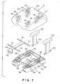
- Fig. 7 is an exploded perspective view of the booster seat shown in Fig. 6;
- Figs. 8A and 8B are diagrammatic sectional views of assistance in explaining the operation of the booster seat shown in Fig. 6, in which Fig. 8A shows a state where a seat member is lowered and Fig. 8B shows a state where the seat member is raised; and
- Figs. 9A and 9B are diagrammatic sectional views of assistance in explaining the operation of the booster seat shown in Fig. 6, in which Fig. 9A shows a state where armrests are spaced a long distance apart and Fig. 3B shows a state where the armrest are spaced a short distance apart.
-
- Figs. 1 to 3 show a booster seat in a first embodiment of the present invention.
- Referring to Fig. 1, a
booster seat 10 has abase 11 to be mounted on and fastened to aseat 51 of a vehicle, such as an automobile, aseat member 14 placed on thebase 11 and having asupport portion 14a for supporting a child thereon andarmrests support portion 14a of theseat member 14, respectively, to support the arms of the child seated on theseat member 14. Thearmrests side members support portion 14a of theseat member 14 on thebase 11, respectively. - As shown in Fig. 2, a plurality of tapered, wedge-
shaped blocks side members side members shaped blocks side members support portion 14a, respectively, i.e., toward each other. The wedge-shaped blocks 17 and the wedge-shaped blocks 18 are arranged alternately. The wedge-shaped blocks upper surfaces - The
seat member 14 is placed on the wedge-shapedblocks seat member 14 facing the wedge-shaped blocks upper surfaces seat member 14 has askirt 19 forming a front wall. -
Recesses 15 are formed in the side walls of thebase 11. The wedge-shaped blocks side members recesses 15 into thebase 11. Thebase 11 has aguide surface 16 flush with the bottom surfaces of therecesses 15 and extending between therecesses 15. Theside members shaped blocks base 11 in directions along the width of thesupport portion 14a to raise and lower theseat member 14 relative to thebase 11 by the cooperative action of the slopingupper surfaces shaped blocks bottom surface 14b of theseat member 14. The distance between thearmrests side members shaped blocks base 11 in directions along the width of thesupport portion 14a. - The wedge-
shaped blocks seat member 14 vertically relative to thebase 11 to adjust the height of thesupport portion 14a of theseat member 14. Theside members armrests seat member 14 caused by the wedge-shaped blocks side members armrests support portion 14a of theseat member 14 is increased by the seat height adjusting mechanism, and is increased by the armrest adjusting mechanism when the height of thesupport portion 14a of theseat member 14 is decreased by the seat height adjusting mechanism. - The operation of the booster seat in the first embodiment will be described hereinafter.
- Fig. 3A shows the
booster seat 10 shown in Figs. 1 and 2 in a state where thearmrests support portion 14a is at a minimum height H1. - As the
side members upper surfaces blocks seat member 14 to push up theseat member 14. When the distance between thearmrests support portion 14a is increased to a maximum height H2 (H2 > H1). - Preferably, the
booster seat 10 is provided with positioning members for preventing the longitudinal and lateral displacement of theseat member 14 to ensure the satisfactory operation of thebooster seat 10. For example, it is preferable to prevent the longitudinal and lateral displacement of theseat member 14 by passingbolts 20 through theseat member 14 and screwing the same in threaded holes formed in predetermined portions of the base 11 as shown in Fig. 2. Preferably, helical compression springs 21 are put on thebolts 20 to bias theseat member 14 toward the wedge-shapedblocks seat member 14 effectively from rattling. - Preferably, the wedge-shaped
blocks base 11 by a locking mechanism. For example, it is preferable to form aprojection 22 on one side surface of each of the wedge-shapedblocks projections 23 on theguide surface 16 of the base 11 at predetermined intervals to engage theprojection 22 in a space between theadjacent projections 23 as shown in Fig. 4 to retain each of the wedge-shapedblocks - It is preferable to interlock the wedge-shaped
block 17 projecting from one theside member 12 and the wedge-shapedblock 18 projecting from theside member 13 and adjacent to the wedge-shapedblock 17 by an interlocking mechanism. For example, it is preferable to move the wedge-shapedblocks parallel racks blocks pinion 26 supported on the base 11 with theracks - A booster seat in a second embodiment of the present invention will be described with reference to Figs. 6 to 9B.
- Referring to Fig. 6, a
booster seat 30 has a base 32 to be mounted on and fastened to aseat 51 of a vehicle, such as an automobile, aseat member 31 placed on thebase 32 and having asupport portion 31a for supporting a child thereon,armrests 33 disposed on the opposite sides of thesupport portion 31a of theseat member 31, respectively, to support the arms of the child seated on theseat member 31 and an operatingbar 34 disposed between the base 32 and theseat member 31. - As shown in Figs. 6 and 7, four box-shaped
protrusions 35 having a rectangular sectional shape.Slots 36 are formed in the side walls of the box-shapedprotrusions 35 so as to slope at an inclination to a direction along the length of thesupport portion 31a. Twoopenings 37 are formed in thesupport portion 31a of theseat member 31. Thearmrests 33 are passed through theopenings 37. - Four box-shaped
cavities 38 are formed in the base 32 to receive the box-shapedprotrusions 35 of theseat member 31, respectively. Substantially horizontal,longitudinal slots 39 are formed in side walls of the box-shapedcavities 38. - The
armrests 33 are provided at their lower ends withlongitudinal shafts 40, respectively. Theshafts 40 are parallel to the length of thesupport portion 31a and are fitted in bearing portions 43 (Fig. 6) formed in thebase 32, such that thearmrests 33 are able to turn on theshafts 40. - The operating
bar 34 is provided with fourpins 41 laterally projecting from the side surfaces thereof in directions parallel to the width of thesupport portion 31a of theseat member 31. Ahandle 42 is formed in a front portion of the operatingbar 34. - The
seat member 31 is put on the base 32 so as to cover the base 32 with the box-shapedprotrusions 35 of theseat member 31 received in the box-shapedcavities 38 of thebase 32, respectively. The operatingbar 34 is inserted from the front side of the base 32 in a space between theseat member 31 and thebase 32, and thepins 41 of the operatingbar 34 are engaged in theslots seat member 31 and thebase 32, respectively. Theshafts 40 of thearmrests 33 extended through theopenings 37 of theseat member 31 are fitted in the bearing portions 43 (Fig. 6) formed in thebase 32. Thus, theseat member 31 is able to move only vertically because the box-shapedprotrusions 35 are fitted in the box-shapedcavities 38. When the operatingbar 34 is moved longitudinal on thebase 32 along thesupport portion 31a, theseat member 31 is moved vertically relative to thebase 32 by the cooperative action of thepins 41 of the operatingbar 34 and theslots member 31 and thebase 32. As theseat member 31 is moved vertically relative to thebase 32, thearmrests 33 turn in a plane perpendicular to the length of thesupport portion 31a under the restriction of theopenings 37, so that the distance between thearmrests 33 is changed accordingly. - The operating
bar 34 provided with thepins 41, the side walls provided with theslots 39 of thebase 32 and the side walls provided with theslots 36 of the box-shapedprotrusions 35 of theseat member 31 form a seat height adjusting mechanism for vertically moving theseat member 31 relative to thebase 32 for the adjustment of thesupport portion 31a of theseat member 31. The bearingportions 43 and portions provided with theopenings 37 of theseat member 31 form an armrest adjusting mechanism for adjusting the distance between thearmrests 33 in coordination with the vertical movement of theseat member 31 caused by operating the operatingbar 34. The distance between thearmrests 33 is decreased by the armrest adjusting mechanism when the height of thesupport portion 31a of theseat member 31 is increased by the seat height adjusting mechanism and is increased when the height of thesupport portion 31a of theseat member 31 is decreased. - The operation of the booster seat in the second embodiment will be described hereinafter.
- Fig. 8A shows a state of the
booster seat 30 shown in Figs. 6 and 7. The operatingbar 34 is moved longitudinally to move thepins 41 of the operatingbar 34 in theslots 39 of thebase 32. In Fig. 8A, the operatingbar 34 is moved to its innermost position and thepins 41 of the operatingbar 34 are located at the rear ends of theslots 39 of thebase 32, respectively. In this state, theseat member 31 is held at a minimum height H1 (Fig. 9A). - When the operating
bar 34 is pulled forward in the state shown in Fig. 8A, thepins 41 of the operatingbar 34 move in theslots 39 of thebase 32 and push up theseat member 31. When thepins 41 of the operatingbar 34 are located at the front ends of theslots 39 as shown in Fig. 8B, theseat member 31 is held at a maximum height H2 (Fig. 9B). - Meanwhile, the
armrests 33 are turned away from each other and are inclined at a large inclination such that the distance between thearmrests 33 increases to a maximum distance W1 as shown in Fig. 9A when theseat member 31 is held at the minimum height H1. - As the
seat member 31 is raised, thearmrests 33 are turned under the restriction of theopenings 37 of theseat member 31 and approach an upright position. When thesupport portion 31a reaches the maximum height H2 (H2 > H1), the distance between thearmrests 33 decreases to a minimum distance W2 (W2 < W1). - The distance between the
armrests 33 must decrease as the height of thesupport portion 31a of theseat member 31 increases. Therefore, the distance L1 between the bearingportions 43 formed on the base 32 must be smaller than the distance L2 between theopenings 37 of the seat member 31 (L1 < L2). - Preferably, the
booster seat 30 is provided with a locking mechanism for locking the operatingbar 34 on the base 32 to ensure the satisfactory operation of thebooster seat 30. For example, it is preferable to form a plurality ofsemicircular recesses 36a at equal intervals in the upper edges of theslots 36 of theseat member 31 as shown in Figs. 8A and 8B. When thepins 41 of the operatingbar 34 drop into thesemicircular recesses 36a, respectively, the operatingbar 34 is restrained from longitudinal movement and hence theseat member 31 can be securely held at a desired height. When theseat member 31 is depressed with thepins 41 of the operatingbar 34 located at predetermined positions in theslots 39 of thebase 32, respectively, theseat member 31 is lowered, and thepins 41 of the operatingbar 34 move to the right as viewed in Figs. 8A and 8B and drop into thenearest recesses 36a on the upper side of the predetermined positions, respectively. A mechanism that locks the operatingbar 34 directly may be employed instead of the foregoing locking mechanism. - The
seat member 31 may be moved vertically by any optional mechanism capable of vertically moving theseat member 31 instead of vertically moving theseat member 31 by the operatingbar 34. For example, the wedge-shapedblocks - Although the
armrests 33 are supported pivotally on the base 32 so as to turn in a plane perpendicular to the length of thesupport portion 31a of theseat member 31 under the restriction of theopenings 37 of theseat member 31 in the second embodiment, thearmrests 33 may be operated by any optional turning mechanism provided that the turning mechanism is able to turn thearmrests 33 in coordination with the vertical movement of theseat member 31. For example, thearmrests 33 may be supported for tuning on theseat member 31 and may be connected to thebase 32 by links. - Although the
slots 39 of the base 32 are extended horizontally along the length of thesupport portion 31a and theslots 36 of theseat member 31 are extended so as to slope at an inclination to a direction along the length of thesupport portion 31a in the second embodiment, it is only necessary that theslots 36 and theslots 39 are inclined relative to each other. For example, theslots 39 of the base 32 may be extended so as to slope at an inclination to a direction along the length of thesupport portion 31a and theslots 36 of theseat member 31 may be substantially horizontally extended along the length of thesupport portion 31a.
Claims (12)
- A booster seat comprising:a base (11; 32) to be mounted on a seat (51) of a vehicle;a seat member (14; 31) placed on the base and having a support portion (14a; 3 la);a pair of armrests (12a, 13a; 33) disposed on opposite sides of the seat member (14; 31), respectively;a seat height adjusting mechanism (17, 18; 34, 35, 36, 39, 41) capable of vertically moving the seat member (14; 31) relative to the base to adjust a height of the support portion (14a; 31a) of the seat member; andan armrest adjusting mechanism (12, 13; 43, 37) capable of adjusting a distance between the armrests (12a, 13a; 33) according to the vertical movement of the seat member (14; 31) by the seat height adjusting mechanism,wherein the distance between the armrests (12a, 13a; 33) is decreased when the height of the support portion (14a; 31a) of the seat member is increased, and is increased when the height of the support portion of the seat member is decreased.
- The booster seat according to claim 1, wherein the seat height adjusting mechanism comprises a plurality of wedge-shaped blocks (17, 18) disposed between the base (11) and the seat member (14), tapered from the opposite sides of the support portion (14a) toward a middle of the support portion, respectively, and each having an upper surface (17a, 18a) serving as a first slope; and a bottom part of the seat member (14) facing the plurality of wedge-shaped blocks (17, 18) and having a second slope (14b) corresponding to the first slopes; and the seat member (14) is moved vertically relative to the base (11) by a cooperative action of the first slopes of the plurality of wedge-shaped blocks and the second slope of the seat member when the plurality of wedge-shaped blocks are moved in directions along the width of the support portion.
- The booster seat according to claim 2, further comprising a locking mechanism (22, 23) for locking the wedge-shaped blocks (17, 18) on the base.
- The booster seat according to claim 2 or 3, further comprising an interlocking mechanism (24-26) for interlocking the adjacent wedge-shaped blocks (17, 18) extending toward each other from the opposite sides of the support portion of the seat member, respectively.
- The booster seat according to one of claims 2 to 4, wherein the armrest adjusting mechanism comprises a pair of side members (12, 13) extended along the opposite sides of the support portion (14a) of the seat member (14) on the base, connected to the outer ends of the plurality of wedge-shaped blocks (17, 18), respectively, and provided with the armrests (12a, 13a), respectively; and the distance between the armrests is adjusted by moving the side members (12, 13) together with the plurality of wedge-shaped blocks (17, 18) on the base in a direction along the width of the support portion.
- The booster seat according to claim 1, wherein the seat height adjusting mechanism (34, 35, 36, 39, 41) comprises an operating bar (34) provided with pins (41) extending along the width of the support portion (31) of the seat member (51); and the base (32) and the seat member (31) are provided with longitudinal slots (39, 36) capable of receiving the pins (41) of the operating bar (34), respectively, and inclined relative to each other; and the seat member (31) is moved vertically relative to the base (32) by a cooperative action of the pins of the operating bar (34) is moved longitudinally on the base in a state where the seat member is able to move only vertically relative to the base.
- The booster seat according to claim 6, wherein the slots (39) formed in the base (32) extend substantially horizontally along the length of the support portion of the seat member and the slots (36) formed in the seat member (31) slope at an inclination of a direction along the length of the support portion of the seat member.
- The booster seat according to claim 6, wherein the slots formed in the base slope at an inclination to a direction along the length of the support portion of the seat member and the slots formed in the seat member extend substantially horizontally along the length of the support portion of the seat member.
- The booster seat according to one of claims 6 to 8, further comprising a locking mechanism (36a, 41) for locking the operating bar (34) on the base (32).
- The booster seat according to claim 9, wherein the locking mechanism includes a plurality of recesses (36a) formed in an upper edge of the slot (36) formed on the seat member or the base and capable of receiving the pin of the operating bar.
- The booster seat according to one of claims 6 to 10, wherein the armrest adjusting mechanism (43, 37) includes a pair of bearing portions (43) formed on the base (32) each for pivotally supporting one end of each armrest (33); and the seat member (31) provided with a pair of openings (37) in which the armrests are inserted, respectively; and the armrests (33) turn in a plane perpendicular to a direction along the length of the support portion (14a) as the seat member (31) is moved vertically relative to the base so that the distance between the armrests is adjusted.
- The booster seat according to claim 11, wherein distance L1 between the bearing portions (43) formed on the base (32) and distance L2 between the openings (37) formed in the seat member (31) meets an inequality: L1 < L2.
Applications Claiming Priority (2)
| Application Number | Priority Date | Filing Date | Title |
|---|---|---|---|
| JP2000006984A JP4338277B2 (en) | 2000-01-14 | 2000-01-14 | Booster seat |
| JP2000006984 | 2000-01-14 |
Publications (3)
| Publication Number | Publication Date |
|---|---|
| EP1116625A2 true EP1116625A2 (en) | 2001-07-18 |
| EP1116625A3 EP1116625A3 (en) | 2003-11-05 |
| EP1116625B1 EP1116625B1 (en) | 2007-04-04 |
Family
ID=18535427
Family Applications (1)
| Application Number | Title | Priority Date | Filing Date |
|---|---|---|---|
| EP01100742A Expired - Lifetime EP1116625B1 (en) | 2000-01-14 | 2001-01-12 | Booster seat |
Country Status (5)
| Country | Link |
|---|---|
| US (1) | US6491343B2 (en) |
| EP (1) | EP1116625B1 (en) |
| JP (1) | JP4338277B2 (en) |
| KR (1) | KR20010076259A (en) |
| DE (1) | DE60127599T2 (en) |
Cited By (4)
| Publication number | Priority date | Publication date | Assignee | Title |
|---|---|---|---|---|
| EP2364875A3 (en) * | 2010-03-12 | 2013-08-07 | Curt Würstl Vermögensverwaltungs-GmbH & Co. KG | Child safety seat |
| WO2016177755A1 (en) * | 2015-05-06 | 2016-11-10 | Dorel France | Child car seat having adjustable strap guiding elements |
| EP3498531A1 (en) * | 2017-12-18 | 2019-06-19 | Interco Gesellschaft für die Planung und den Vertrieb von Reha Hilfen mbH | Device, in particular seat shell, with a plurality of mobile adjustment elements |
| CN115087379A (en) * | 2019-12-27 | 2022-09-20 | 曼玛斯&帕帕斯控股有限公司 | Auxiliary seat |
Families Citing this family (26)
| Publication number | Priority date | Publication date | Assignee | Title |
|---|---|---|---|---|
| US6705675B1 (en) * | 2000-05-08 | 2004-03-16 | Graco Children's Products Inc. | Adjustable child seat for toddlers to small children |
| US7066536B2 (en) * | 2002-02-11 | 2006-06-27 | Graco Children's Products Inc. | Child seat |
| US7300113B2 (en) * | 2003-04-29 | 2007-11-27 | Thomas Charles Baloga | Child's booster seat |
| US7090294B2 (en) * | 2003-06-04 | 2006-08-15 | Cosco Management, Inc. | Juvenile vehicle booster seat kit |
| CA2465939C (en) | 2004-04-30 | 2010-08-24 | Mattel, Inc. | Infant support with selectively covered tray |
| DE102007017352B4 (en) * | 2007-04-12 | 2010-12-09 | Honda Motor Co., Ltd. | Child seat |
| DE102007057617B4 (en) * | 2007-11-30 | 2009-12-24 | Airbus Deutschland Gmbh | Device for tool-free height adjustment of an assembly |
| US7828381B2 (en) * | 2008-04-30 | 2010-11-09 | Evenflo Company, Inc. | Recline mechanism for a child restraint seat |
| CN101659224B (en) | 2008-06-25 | 2011-11-23 | 明门香港股份有限公司 | child seat |
| US8240762B2 (en) * | 2009-12-03 | 2012-08-14 | Louis Herzberg | Single, multiple and integrated car seat systems |
| US8616370B2 (en) * | 2010-10-28 | 2013-12-31 | Arrows Up, Inc. | Bulk material shipping container |
| US8887914B2 (en) | 2010-10-28 | 2014-11-18 | Arrows Up, Inc. | Bulk material shipping container |
| US20120211533A1 (en) * | 2011-02-23 | 2012-08-23 | Simmons Katherine L | Child portable potty seat caddy |
| US8998318B2 (en) * | 2011-08-18 | 2015-04-07 | Cosco Management, Inc. | Child restraint with tiltable juvenile seat |
| US8985554B2 (en) * | 2011-08-31 | 2015-03-24 | Aktiebolaget Skf | System and method for lifting and lowering objects |
| US8870284B2 (en) * | 2012-06-27 | 2014-10-28 | Brian Chapman | Adjustable booster seat |
| US8905476B2 (en) * | 2012-08-15 | 2014-12-09 | Evenflo Company, Inc. | Adjustment mechanism for juvenile product |
| EP2883742A1 (en) * | 2013-12-11 | 2015-06-17 | Airbus Operations GmbH | Seat modification assembly and aircraft passenger seat comprising a seat modification assembly |
| CA2945454C (en) | 2016-06-30 | 2023-11-07 | Arrows Up, Llc | Bulk material shipping container |
| US10625637B2 (en) * | 2016-12-08 | 2020-04-21 | Wonderland Switzerland Ag | Adjustable child device |
| US10315539B2 (en) | 2017-05-09 | 2019-06-11 | Dorel Juvenile Group, Inc. | Child restraint with vehicle seatbelt management system |
| KR102013063B1 (en) * | 2018-02-28 | 2019-08-21 | 이하나 | Width adjustment available chairs |
| US11661235B2 (en) | 2018-10-15 | 2023-05-30 | Sandbox Enterprises, Llc | Bulk material shipping container top wall assembly and bulk material shipping container having a top wall assembly |
| US10926940B2 (en) | 2018-11-20 | 2021-02-23 | Sandbox Enterprises, Llc | Bulk material shipping container |
| DE102020119358B4 (en) | 2020-07-22 | 2023-01-19 | Audi Aktiengesellschaft | Arrangement for a vehicle seat |
| US12527415B2 (en) | 2023-08-16 | 2026-01-20 | Erik Hansen | Musical booster seat device |
Family Cites Families (9)
| Publication number | Priority date | Publication date | Assignee | Title |
|---|---|---|---|---|
| CA1221899A (en) * | 1984-06-14 | 1987-05-19 | Jerry N. Moscovitch | Adjustable car seat |
| IT1231847B (en) * | 1989-09-14 | 1992-01-14 | Monbebe Srl | ADJUSTABLE SUPPORT SEAT, PARTICULARLY FOR THE TRANSPORT OF CHILDREN IN MOTOR VEHICLES. |
| US5263668A (en) * | 1991-10-15 | 1993-11-23 | Ast Research, Inc. | Computer pedestal |
| GB9301342D0 (en) * | 1993-01-23 | 1993-03-17 | Britax Roemer Kindersicherheit Gmbh | Child's safety device |
| US5385387A (en) * | 1993-10-01 | 1995-01-31 | Lisco, Inc. | Child carrier with detachable base |
| AUPN649595A0 (en) * | 1995-11-10 | 1995-12-07 | Britax Child-Care Products Pty Ltd | Reclining mechanism and latch for child safety seat |
| JPH11278116A (en) * | 1998-01-27 | 1999-10-12 | Aprica Kassai Inc | Seat for young person |
| US6033019A (en) * | 1998-10-21 | 2000-03-07 | The First Years Inc. | Feeding seat |
| US6142440A (en) * | 1999-03-25 | 2000-11-07 | Great Northern Corporation | Large roll support having reinforcement bridges |
-
2000
- 2000-01-14 JP JP2000006984A patent/JP4338277B2/en not_active Expired - Fee Related
-
2001
- 2001-01-12 DE DE60127599T patent/DE60127599T2/en not_active Expired - Fee Related
- 2001-01-12 EP EP01100742A patent/EP1116625B1/en not_active Expired - Lifetime
- 2001-01-12 KR KR1020010001803A patent/KR20010076259A/en not_active Withdrawn
- 2001-01-16 US US09/759,520 patent/US6491343B2/en not_active Expired - Fee Related
Non-Patent Citations (1)
| Title |
|---|
| None |
Cited By (6)
| Publication number | Priority date | Publication date | Assignee | Title |
|---|---|---|---|---|
| EP2364875A3 (en) * | 2010-03-12 | 2013-08-07 | Curt Würstl Vermögensverwaltungs-GmbH & Co. KG | Child safety seat |
| WO2016177755A1 (en) * | 2015-05-06 | 2016-11-10 | Dorel France | Child car seat having adjustable strap guiding elements |
| FR3035832A1 (en) * | 2015-05-06 | 2016-11-11 | Dorel France Sa | CHILD CAR SEAT HAVING ADJUSTABLE STRAP GUIDING ELEMENTS. |
| FR3035833A1 (en) * | 2015-05-06 | 2016-11-11 | Dorel France Sa | CHILD CAR SEAT HAVING ADJUSTABLE STRAP GUIDING ELEMENTS |
| EP3498531A1 (en) * | 2017-12-18 | 2019-06-19 | Interco Gesellschaft für die Planung und den Vertrieb von Reha Hilfen mbH | Device, in particular seat shell, with a plurality of mobile adjustment elements |
| CN115087379A (en) * | 2019-12-27 | 2022-09-20 | 曼玛斯&帕帕斯控股有限公司 | Auxiliary seat |
Also Published As
| Publication number | Publication date |
|---|---|
| KR20010076259A (en) | 2001-08-11 |
| JP4338277B2 (en) | 2009-10-07 |
| EP1116625A3 (en) | 2003-11-05 |
| DE60127599D1 (en) | 2007-05-16 |
| JP2001199267A (en) | 2001-07-24 |
| EP1116625B1 (en) | 2007-04-04 |
| US6491343B2 (en) | 2002-12-10 |
| US20010008349A1 (en) | 2001-07-19 |
| DE60127599T2 (en) | 2007-12-13 |
Similar Documents
| Publication | Publication Date | Title |
|---|---|---|
| EP1116625B1 (en) | Booster seat | |
| EP1277423B1 (en) | Height adjustable child seat | |
| EP2179883B1 (en) | Slide locking mechanism for seat | |
| US7673940B2 (en) | Height-adjustment mechanism for juvenile seat | |
| US7562926B2 (en) | Walk-in-device | |
| US7637469B2 (en) | Seat sliding apparatus for a vehicle | |
| US7387336B2 (en) | Child seat | |
| US6176460B1 (en) | Seat sliding apparatus for a vehicle | |
| US11999272B2 (en) | Child safety seat | |
| EP1029733B1 (en) | Slide device of vehicle seat | |
| CN101678782A (en) | Slide mechanism of vehicle seat | |
| KR20120011317A (en) | Child car seat | |
| US20030094558A1 (en) | Seat slide device | |
| KR19980086996A (en) | Car Seat Slide Unit | |
| JPH11512365A (en) | Vehicle seat truck assembly | |
| CN113859068B (en) | child safety seat | |
| US5048787A (en) | Slide rail for automotive seat | |
| EP1757484A2 (en) | Child car seat | |
| JP2004122798A (en) | Walk-in device for vehicle seats | |
| US20240375561A1 (en) | Child restraint | |
| EP0858927B1 (en) | Reclining device | |
| JP4169887B2 (en) | Locking / unlocking mechanism of case lock body | |
| CN115503574A (en) | Seat adjusting structure and child safety seat | |
| US20250353408A1 (en) | Sliding device | |
| JPH10135A (en) | Chair armrest height adjustment device |
Legal Events
| Date | Code | Title | Description |
|---|---|---|---|
| PUAI | Public reference made under article 153(3) epc to a published international application that has entered the european phase |
Free format text: ORIGINAL CODE: 0009012 |
|
| AK | Designated contracting states |
Kind code of ref document: A2 Designated state(s): AT BE CH CY DE DK ES FI FR GB GR IE IT LI LU MC NL PT SE TR |
|
| AX | Request for extension of the european patent |
Free format text: AL;LT;LV;MK;RO;SI |
|
| PUAL | Search report despatched |
Free format text: ORIGINAL CODE: 0009013 |
|
| AK | Designated contracting states |
Kind code of ref document: A3 Designated state(s): AT BE CH CY DE DK ES FI FR GB GR IE IT LI LU MC NL PT SE TR |
|
| AX | Request for extension of the european patent |
Extension state: AL LT LV MK RO SI |
|
| RIC1 | Information provided on ipc code assigned before grant |
Ipc: 7A 47D 1/10 B Ipc: 7B 60N 2/28 A |
|
| 17P | Request for examination filed |
Effective date: 20040428 |
|
| AKX | Designation fees paid |
Designated state(s): DE ES FR GB IT |
|
| GRAP | Despatch of communication of intention to grant a patent |
Free format text: ORIGINAL CODE: EPIDOSNIGR1 |
|
| GRAS | Grant fee paid |
Free format text: ORIGINAL CODE: EPIDOSNIGR3 |
|
| GRAA | (expected) grant |
Free format text: ORIGINAL CODE: 0009210 |
|
| AK | Designated contracting states |
Kind code of ref document: B1 Designated state(s): DE ES FR GB IT |
|
| REG | Reference to a national code |
Ref country code: GB Ref legal event code: FG4D |
|
| REF | Corresponds to: |
Ref document number: 60127599 Country of ref document: DE Date of ref document: 20070516 Kind code of ref document: P |
|
| PG25 | Lapsed in a contracting state [announced via postgrant information from national office to epo] |
Ref country code: ES Free format text: LAPSE BECAUSE OF FAILURE TO SUBMIT A TRANSLATION OF THE DESCRIPTION OR TO PAY THE FEE WITHIN THE PRESCRIBED TIME-LIMIT Effective date: 20070715 |
|
| EN | Fr: translation not filed | ||
| PLBE | No opposition filed within time limit |
Free format text: ORIGINAL CODE: 0009261 |
|
| STAA | Information on the status of an ep patent application or granted ep patent |
Free format text: STATUS: NO OPPOSITION FILED WITHIN TIME LIMIT |
|
| 26N | No opposition filed |
Effective date: 20080107 |
|
| PG25 | Lapsed in a contracting state [announced via postgrant information from national office to epo] |
Ref country code: IT Free format text: LAPSE BECAUSE OF FAILURE TO SUBMIT A TRANSLATION OF THE DESCRIPTION OR TO PAY THE FEE WITHIN THE PRESCRIBED TIME-LIMIT Effective date: 20070404 Ref country code: FR Free format text: LAPSE BECAUSE OF FAILURE TO SUBMIT A TRANSLATION OF THE DESCRIPTION OR TO PAY THE FEE WITHIN THE PRESCRIBED TIME-LIMIT Effective date: 20071130 |
|
| PGFP | Annual fee paid to national office [announced via postgrant information from national office to epo] |
Ref country code: GB Payment date: 20071211 Year of fee payment: 8 |
|
| PGFP | Annual fee paid to national office [announced via postgrant information from national office to epo] |
Ref country code: DE Payment date: 20080110 Year of fee payment: 8 |
|
| PG25 | Lapsed in a contracting state [announced via postgrant information from national office to epo] |
Ref country code: FR Free format text: LAPSE BECAUSE OF FAILURE TO SUBMIT A TRANSLATION OF THE DESCRIPTION OR TO PAY THE FEE WITHIN THE PRESCRIBED TIME-LIMIT Effective date: 20070404 |
|
| GBPC | Gb: european patent ceased through non-payment of renewal fee |
Effective date: 20090112 |
|
| PG25 | Lapsed in a contracting state [announced via postgrant information from national office to epo] |
Ref country code: DE Free format text: LAPSE BECAUSE OF NON-PAYMENT OF DUE FEES Effective date: 20090801 |
|
| PG25 | Lapsed in a contracting state [announced via postgrant information from national office to epo] |
Ref country code: GB Free format text: LAPSE BECAUSE OF NON-PAYMENT OF DUE FEES Effective date: 20090112 |