EP1116595A1 - Auxiliary printing implement and assembling jig therefor and recording device - Google Patents
Auxiliary printing implement and assembling jig therefor and recording device Download PDFInfo
- Publication number
- EP1116595A1 EP1116595A1 EP00935642A EP00935642A EP1116595A1 EP 1116595 A1 EP1116595 A1 EP 1116595A1 EP 00935642 A EP00935642 A EP 00935642A EP 00935642 A EP00935642 A EP 00935642A EP 1116595 A1 EP1116595 A1 EP 1116595A1
- Authority
- EP
- European Patent Office
- Prior art keywords
- printing
- printed
- dial
- printing position
- recording device
- Prior art date
- Legal status (The legal status is an assumption and is not a legal conclusion. Google has not performed a legal analysis and makes no representation as to the accuracy of the status listed.)
- Granted
Links
- 239000000463 material Substances 0.000 claims abstract description 94
- 238000007599 discharging Methods 0.000 claims description 2
- 238000003780 insertion Methods 0.000 description 4
- 230000037431 insertion Effects 0.000 description 4
- 239000007767 bonding agent Substances 0.000 description 2
- 230000002093 peripheral effect Effects 0.000 description 2
- 238000005299 abrasion Methods 0.000 description 1
- 239000002390 adhesive tape Substances 0.000 description 1
- XAGFODPZIPBFFR-UHFFFAOYSA-N aluminium Chemical compound [Al] XAGFODPZIPBFFR-UHFFFAOYSA-N 0.000 description 1
- 229910052782 aluminium Inorganic materials 0.000 description 1
- 238000000034 method Methods 0.000 description 1
- 239000000049 pigment Substances 0.000 description 1
- 239000007921 spray Substances 0.000 description 1
Images





Classifications
-
- B—PERFORMING OPERATIONS; TRANSPORTING
- B41—PRINTING; LINING MACHINES; TYPEWRITERS; STAMPS
- B41J—TYPEWRITERS; SELECTIVE PRINTING MECHANISMS, i.e. MECHANISMS PRINTING OTHERWISE THAN FROM A FORME; CORRECTION OF TYPOGRAPHICAL ERRORS
- B41J13/00—Devices or arrangements of selective printing mechanisms, e.g. ink-jet printers or thermal printers, specially adapted for supporting or handling copy material in short lengths, e.g. sheets
- B41J13/10—Sheet holders, retainers, movable guides, or stationary guides
- B41J13/14—Aprons or guides for the printing section
-
- B—PERFORMING OPERATIONS; TRANSPORTING
- B41—PRINTING; LINING MACHINES; TYPEWRITERS; STAMPS
- B41J—TYPEWRITERS; SELECTIVE PRINTING MECHANISMS, i.e. MECHANISMS PRINTING OTHERWISE THAN FROM A FORME; CORRECTION OF TYPOGRAPHICAL ERRORS
- B41J11/00—Devices or arrangements of selective printing mechanisms, e.g. ink-jet printers or thermal printers, for supporting or handling copy material in sheet or web form
- B41J11/36—Blanking or long feeds; Feeding to a particular line, e.g. by rotation of platen or feed roller
- B41J11/42—Controlling printing material conveyance for accurate alignment of the printing material with the printhead; Print registering
-
- B—PERFORMING OPERATIONS; TRANSPORTING
- B41—PRINTING; LINING MACHINES; TYPEWRITERS; STAMPS
- B41J—TYPEWRITERS; SELECTIVE PRINTING MECHANISMS, i.e. MECHANISMS PRINTING OTHERWISE THAN FROM A FORME; CORRECTION OF TYPOGRAPHICAL ERRORS
- B41J13/00—Devices or arrangements of selective printing mechanisms, e.g. ink-jet printers or thermal printers, specially adapted for supporting or handling copy material in short lengths, e.g. sheets
-
- B—PERFORMING OPERATIONS; TRANSPORTING
- B41—PRINTING; LINING MACHINES; TYPEWRITERS; STAMPS
- B41J—TYPEWRITERS; SELECTIVE PRINTING MECHANISMS, i.e. MECHANISMS PRINTING OTHERWISE THAN FROM A FORME; CORRECTION OF TYPOGRAPHICAL ERRORS
- B41J3/00—Typewriters or selective printing or marking mechanisms characterised by the purpose for which they are constructed
- B41J3/407—Typewriters or selective printing or marking mechanisms characterised by the purpose for which they are constructed for marking on special material
- B41J3/4073—Printing on three-dimensional objects not being in sheet or web form, e.g. spherical or cubic objects
Definitions
- the present invention relates to a printing aid which is used when printing is performed on a material to be printed by a recording device, to an assembly jig therefor, and to a recording device having the printing aid.
- a printer device in particular, a so-called personal use printer device privately used by an individual person at home has been, for example, as shown in Fig. 12.
- a printer device 1 includes a printer body 1b, and a stage la, which is connected to the printer body 1b and which places thereon, for example, a paper, which is a material to be printed.
- the paper placed on the stage la is guided by a feed roller (not shown) provided in the printer body 1b into the printer body 1b.
- an angle shown in Fig. 12 is provided to a connecting part between the stage la and the inside of the printer body 1b. This is intended to allow the feed roller of the printer body 1b to easily hold the paper because the paper placed on the stage 1a is positioned in a direction to approach the feed roller of the printer body 1b by its own weight.
- the paper guided to the inside of the printer body 1b is guided to a printing position by the feed roller. Since a printer head (not shown) is provided at the printing position, characters and the like can be printed on the paper by ejecting ink contained in the printer head from a nozzle.
- the thus-printed paper is discharged by a discharge roller (not shown) provided in the printer body 1b toward a discharge pad lc, is placed on the discharge pad 1c, and is then stopped. In this state, the user receives a printed paper from the discharge pad 1c.
- printing cannot be performed on a material other than the paper, for example, on a dial of a timepiece, which is relatively small, hard, and thick.
- the present invention has as its object to provide a printing aid which makes it possible to print on various types of materials to be printed by a recording device, such as a printer device, to provide an assembly jig therefor, and to provide a printer device having the printing aid.
- a printing jig according to the invention of Claim 1 including a printing position-determining member for determining a position of a material to be printed on a printing position of a recording device, and a placement member for material to be printed for placing the material to be printed at a portion corresponding to the printing position determined by the printing position-determining member.
- the printing jig since the printing jig includes a printing position-determining member for determining a position of a material to be printed on a printing position of a recording device, and a placement member for material to be printed for placing the material to be printed at a portion corresponding to the printing position determined by the printing position-determining member, if the material to be printed is placed on the placement member for material to be printed, the material to be printed can be positioned at the printing position by the printing position-determining member.
- the above object is achieved by a printing aid of the features of Claim 1, wherein the printing position-determining member is formed of a base material having flexibility.
- the printing position-determining member is formed of a base material having flexibility, the base material having flexibility is guided to a guide section of the recording device while being bent.
- the base material having flexibility is bent instead of the material to be printed, and is correctly guided into the recording device.
- the above object is achieved by a printing aid of the features of Claim 1, wherein the printing position-determining member is provided with a printing direction-indicating part for indicating a printing direction.
- the printing position-determining member is provided with a printing direction-indicating part for indicating a printing direction, a user does not make a mistake in the printing direction.
- the above object is achieved by a printing aid of the features of Claim 3, wherein the printing direction-indicating part is formed by an arrow and/or a cutout.
- the printing direction-indicating part is formed by an arrow and/or a cutout, the user does not make a mistake in the printing direction of the material to be printed by confirming the arrow and/or the cutout.
- the above object is achieved by a printing aid of the features of any one of Claim 1 to Claim 4, wherein the material to be printed forms a dial of a timepiece, the dial of the timepiece is provided with a mounting pin, and the placement member for material to be printed is formed with a hole for receiving the pin.
- the dial of the timepiece is provided with a mounting pin, and the placement member for material to be printed is formed with a hole for receiving the pin, the pin for mounting the dial of the timepiece, which is the material to be printed, can be arranged in the placement member for material to be printed.
- the above object is achieved by a printing aid of any one of Claim 1 to Claim 5, wherein the placement member for material to be printed is provided with a fixing part for fixing the material to be printed.
- the placement member for material to be printed is provided with a fixing part for fixing the material to be printed, the material to be printed does not shift on the placement member for material to be printed, and is not removed from the placement member for material to be printed.
- the above object is achieve by a printing aid of the features of any one of Claim 1 to Claim 6, wherein the placement member for material to be printed is provided with an ink-collecting part for collecting ink ejected from the recording device.
- the placement member for material to be printed is provided with an ink-collecting part for collecting ink of the recording device, unnecessary ink is collected in the ink-collecting part when the material to be printed is printed. Therefore, printing accuracy of the material to be printed is improved.
- the above object is achieved by a printing aid of the features of any one of Claim 1 to Claim 6, wherein the placement member for material to be printed is formed with a member for absorbing ink ejected from the recording device.
- the placement member for material to be printed is formed with a member for absorbing ink ejected from the recording device, unnecessary ink is absorbed by the member for absorbing the ink ejected from the recording device when the material to be printed is printed. Therefore, printing accuracy of the material to be printed is further improved.
- the above object is achieved by a printing aid of the features of any one of Claim 1 to Claim 7, wherein the placement member for material to be printed is provided with a detaching recess for detaching the material to be printed.
- the placement member for material to be printed is provided with a detaching recess for detaching the material to be printed, the user can easily detach the material to be printed using the detaching recess.
- an assembly jig for a printing aid including a storage section for storing a printing position-determining member, a processing section for processing the printing position-determining member into a required size, and a mounting opening for mounting a placement member for material to be printed having the material to be printed placed thereon at a predetermined position of the printing position-determining member.
- the printing position-determining member is stored in the storage section, and the printing position-determining member can be processed by the processing section into a required size.
- the user uses the mounting opening, whereby the printing member placement member can be accurately mounted to the printing position-determining member.
- the above object can be achieved by the assembly jig for the printing aid according to the features of Claim 10, wherein the mounting opening is provided with a setting recess which corresponds to a holder for holding the placement member for material to be printed and sets up the placement member for material to be printed on the printing position-determining member.
- the mounting opening is provided with a setting recess which corresponds to a holder for holding the placement member for material to be printed and sets up the placement member for material to be printed on the printing position-determining member, the user uses the setting recess, whereby the placement member for material to be printed can be easily set to the printing position-determining member.
- a recording device including a recording device body, a feed section for pulling in an object to a printing position in the recording device body, and a discharge section for discharging the object from the recording device body, wherein the object is a printing aid having a printing position-determining member for determining a position of a material to be printed on a printing position in the recording device, and a placement member for material to be printed for placing the material to be printed at a portion corresponding to the printing position determined by the printing position-determining member.
- the object is a printing aid having a printing position-determining member for determining a position of a material to be printed on a printing position in the recording device, and a placement member for material to be printed for placing the material to be printed at a portion corresponding to the printing position determined by the printing position-determining member. Therefore, if the material to be printed is placed on the placement member for material to be printed, the printing member is positioned at a printing position by the printing position-determining member. For this reason, the material to be printed can be printed in a state of being accurately positioned regardless of the size and the like.
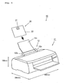
- Fig. 1 is a schematic perspective view showing the configuration of a dial printing machine according to an embodiment of the present invention.
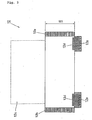
- Fig. 2 is a schematic plan view showing an ASF section in Fig. 1.
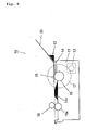
- Fig. 3 is a schematic central sectional view showing a dial printing machine body in Fig. 1.
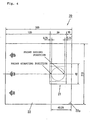
- Fig. 4 is a schematic plan view showing a dial-making jig.
- Fig. 5 is a schematic plan view showing a pallet 21 in Fig. 4.
- Fig. 6 is a schematic plan view of a dial of a timepiece.
- Fig. 7 is a schematic sectional view showing the state where the dial-making jig is set to the ASF section of the dial printing machine.
- Fig. 8 is a schematic sectional view showing the state where the dial-making jig is guided to the inside of the dial printing machine body by rollers of the ASF section.
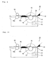
- Fig. 9 is a schematic sectional view showing the state where the dial-making jig is further pulled in by a feed roller and a feed presser roller to reach a print starting position.
- Fig. 10 is a schematic sectional view showing the state where the dial-making jig is moved in a discharge direction by a discharge roller, and the like.
- Fig. 11 is a schematic perspective view showing an assembly jig of the dial-making jig according to the embodiment.
- Fig. 12 is a schematic perspective view showing a conventional printer device.
- Fig. 1 is a view showing a dial printer 10 having a dial-making jig 20, which is a printing aid according to this embodiment, and a dial printing machine body 11 which is a printer body as a recording device.
- the dial-making jig 20 includes, for example, a pallet 21, which is a placement member for material to be printed for placing a material to be printed, for example, a dial 30 of a timepiece, and a film 22, which is a flexible film, including the pallet 21 at a predetermined position.
- dial printing machine body 11 is first provided with an ASF (Auto Sheet Feeder) section 12, which is a feeding section by which a user places the dial-making jig 20.
- ASF Auto Sheet Feeder
- the ASF section 12 is constructed as shown in Fig. 2.
- Fig. 2 is a schematic plan view of the ASF section 12 shown in Fig. 1. That is, the ASF section 12 has a feed support section 12c provided so that the user easily places the dial-making jig 20, and two guides 12a, 12b for aligning both sides of the dial-making jig 20 when the dial-making jig 20 is placed on the ASF section 12.
- the ASF section 12 includes two rollers 12d, 12d, and two guides 12e, 12e for feeding the dial-making jig 20 aligned by the guides 12a, 12b to the inside of the dial printing machine body 11.
- the guides 12e, 12e perform function of guide parts for the dial-making jig 20 being correctly fed to the inside of the dial printer body 11.
- the guides 12e, 12e are formed to have the length of, for example, about 105 mm as viewed from above.
- the size of the dial printing machine body 11, not including the feed support section 12c is for example, 199 mm long, 467 mm wide, and 296 mm deep, as shown in Fig. 1. This is the size of a so-called personal use-type printer used by an individual at home for private purposes.
- Fig. 3 is a central vertical sectional view of the dial printing machine body 11 in Fig. 1.
- the arrow of a broken line shown in Fig. 3 shows a path on which the dial-making jig 20 moves in the dial printing machine body 11.
- the dial printing machine body 11 is provided with a rear platen 14 for receiving the dial-making jig 20 fed from the ASF section 12 and for connecting the dial-making jig 20 to the feed roller 16.
- the feed roller 16 for receiving the dial-making jig 20 from the rear platen 14 and for feeding the dial-making jig 20 to a front platen 14a, which is at the printing position, a feed presser roller 15, and a driving gear 17.
- the dial-making jig 20 is pressed from above and below by the feed roller 16 and the feed presser roller 15, whereby the dial-making jig 20 can be precisely fed to the front platen 14a.
- a printer head 19 is disposed above the front platen 14a, and ink, such as pigment, is ejected from a nozzle of the printer head 19, whereby a dial 30 of a time piece placed on the dial-making jig 20 is printed.
- the printer head 19 is movably supported by a CR shaft 19a shown in Fig. 3.
- the dial-making jig 20 having the printing-ended dial 30 is held by a serrated roller 18 and a discharge roller 18a, which is a discharge section shown in Fig. 3, and is discharged from the dial printer body 11.
- the dial-making jig 20 is constructed, for example, as shown in Fig. 4.
- a film 22, which is a printing position-determining member is formed by cutting a bendable special purpose glossy film into, for example, a sheet of 210 mm long and 185 mm wide, and having a weight of, for example, about 6.85 g.
- a photo-print paper 2 manufactured by EPSON (registered trademark) Inc.
- a photo-quality card 2 manufactured by EPSON (registered trademark) Inc.
- a special purpose OHP sheet manufactured by EPSON (registered trademark) Inc.
- a superfine special purpose paper manufactured by EPSON (registered trademark) Inc.
- a special purpose wood-free plain paper manufactured by EPSON (registered trademark) Inc.
- any material may be used as long as it can maintain environment resistance, abrasion resistance, and paper feed accuracy.
- the film 22 is provided with three arrows for indicating the printing direction, as shown in Fig. 4.
- a cutout 22a showing a rear end part at the time of printing is provided in the lower right corner in the figure. For this reason, the user does not make a mistake in the printing direction by the three arrows and the cutout 22a.
- the pallet 21 is, for example, made of aluminum, and is formed in the size of, for example, 48 mm long and 39 mm wide, and the weight is, for example, 7.19 g. Specifically, the pallet 21 is as shown in Fig. 5.
- the pallet 21 is formed with a quadrangular work placement part 21a for placing the dial of the timepiece 30, which is a material to be printed.
- the work placement part 21a has two work fixing pats 23, which are fixing parts, provided at the upper left and the lower right in the figure.
- the work fixing parts 23, 23 are provided with protrusions 23a at the centers thereof, respectively, and recesses 23b having a depth of 0.3 mm are formed therearound.
- the dial 30 of the timepiece is provided with depressions and projections 31, 31 (see Fig. 6) so as to correspond to the protrusion 23a and the recesses 23b. Therefore, by fitting the depressions and projections 31, 31 of the dial 30 to be printed into the protrusions 23a and the recesses 23b of the work fixing part 23, the dial 30 of the timepiece is fixed to the pallet 21.
- a dial body 32 incorporated into the timepiece is arranged in the center of the dial 30 of the timepiece, and a press-punched groove 33 is provided on the peripheral part thereof.
- quadrangular frames 34 for supporting the dial body 32 are disposed on the outside the thereof.
- the dial 30 of the timepiece to which the frame 34 is attached is placed on the work placement part 21a of the pallet 21 shown in Fig. 5.
- the pallet 21 is provided with two holes 21c for the pins, as shown in Fig. 5.
- the holes 21c, 21c for pins are provided corresponding to mounting pins formed on the reverse face of the dial 30 of the timepiece shown in Fig. 6. Since each mounting pin has a height of 1.3 mm to 1.6 mm, the holes 21c, 21c are formed so that they can accommodate the mounting pins having the height. In addition, in order to accommodate the mounting pins, the thickness of the pallet 21 is about 1.7 mm.
- an ink-collecting part 21b having a diameter of 3 mm, and a depth of 0.3 mm is provided in the center of the work placement part 21a of the pallet 21.
- an ink-collecting part 21b having a depth of 0.3 mm is provided in the outer peripheral part of the ink-collecting part 21b.
- ink-collecting parts 21b, 21b are provided for the following reasons. That is, as shown in Fig. 6, the dial 30 of the timepiece is provided with a circular hole 35 for passing a shaft of an hour hand or the like through the center of the dial body 32. In addition, the press-punched groove 33 is also provided as described above. For this reason, when printing is performed with the dial printer 10, the ink may leak from the hole 35 and the groove 33 to enter in between the dial 30 of the timepiece and the pallet 21.
- the ink-collecting parts 21b are provided at portions of the pallet 21 corresponding to the hole 35 and the groove 35 from which the ink may leak.
- an absorbing sheet which is a member for absorbing the ink
- the absorbing sheet absorbs the leaked ink, so that the ink leakage can be prevented more effectively.
- the pallet 21 is provided with two detaching recesses 21d on both sides thereof, as shown in Fig. 5.
- the detaching recesses 21d, 21d serve as finger-hooking parts when the user detaches the dial 30 of the timepiece from the pallet 21. Therefore, the detaching recesses 21d, 21d are formed to be 0.5 mm deep and 14 mm wide. That is, the width is set in consideration of the width of the finger of a user.
- the pallet 21 is constructed as described above, and the dial 30 of the timepiece is placed and fixed thereon as described above.
- the dial printing machine 10 is constructed as described above. The operation and the like of the dial printing machine 10 will be described below. In addition, the positional relationship between the pallet 21 of the dial-making jig 20 and the film 22 will be also described while describing the operation and the like.
- the user places and fixes the dial 30 of the timepiece on the pallet 21 of the dial-making jig 20, as described above. Thereafter, the dial-making jig 20 is set to the ASF section 12 of the dial printing machine 10. Fig. 7 shows this state.
- Fig. 8 shows this state.
- a part of the dial-making jig 20 reaches the feed roller 16 and the feed presser roller 15.
- Fig. 9 shows this state.
- a front end part of the dial-making jig 20 reaches the serrated roller 18 and the discharge roller 18a, and the central part thereof is supported by the front platen 14a, the feed presser roller 15, and the feed roller 16.
- a rear end part thereof passes through the ASF section 12, and is supported by the rear platen 14. In this way, it is important that the dial-making jig 20 is placed almost horizontally in the dial printing machine body 11.
- the length from the print starting on the pallet 21 to the right end of the film 22 is 49.25 mm. This is intended to start printing when the right end of the film 22 passes through the ASF section 12 and reaches the rear platen 14. That is, this is due to the fact that the length from the right end of the rear platen 14 to the printing position of the front platen 14a is 50 mm, as shown in Fig. 3.
- the length between the left end of the film 22 and the left end of the pallet 21 is set to 130 mm.
- Fig. 10 shows the state of this time. Even at the time of completion of printing, it is necessary that the dial-making jig 20 abut against the feed roller 16 and the discharge roller 18a. For this reason, the length between the print ending position of the pallet 21 and the film 22 is 21.75 mm, as shown in Fig. 4. This is because the length between the printing position and the feed roller 16 is 14 mm, as shown in Fig. 3.
- the dial printer 10 By operating the dial printer 10 according to this embodiment as described above, even a material, for example, the dial 30 of the timepiece which is relatively small, hard and thick, unlike a paper, can be printed merely by the preparation of the dial-making jig 20, without preparing a special printer. Therefore, a retail timepiece store or an individual can easily show a favorite pattern and the like on the dial 30 of the timepiece simply by preparing a regular printer device, and the dial-making jig 20.
- the dial-making jig 20 used in the dial printing machine 10 according to this embodiment is assembled as follows.
- an assembly jig 40 of a dial-making jig which is an assembly jig for the printing aid, is provided, as shown in Fig. 11, so that the positional relationship can be set easily with a simple configuration.
- the assembly jig 40 of the dial-making jig includes a film storage section 41 serving as a storage section for storing the film 22, which is a printing position-determining member, and a first cover 42 and a second cover 43 placed on the film 22 from above.
- a cutting section 44 which is a working section, is provided between the first cover 42 and the second cover 43.
- a portion formed by the second cover 43 is 210 mm long and 185 mm wide, which is the size of the film 22 shown in Fig. 4.
- the second cover 43 is provided with a pallet insertion hole 45, which is a mounting opening.
- the pallet insertion hole 45 is provided with setting recesses 45a, 45a so that a holder (not shown) for holding the pallet 21 can be set on the film 22 in a state of holding the pallet 21.
- the assembly jig 40 of the dial-making jig according to this embodiment is constructed as described above. A method of use thereof will be described below.
- the user stores the film 22 in the film storage section 41. Thereafter, the first cover 42 and the second cover 43 are placed on the film 22. Furthermore, a bonding agent, for example, a spray paste, is applied on the pallet 21, and the pallet 21 is inserted from the pallet insertion hole 45 while the pallet 21 is being picked up and fingers of the use are inserted into the setting recesses 45a and 45a. Then, the pallet 21 is brought into abutment with the film 22. This allows the pallet 21 to be bonded to the film 22 by the bonding agent. Thereafter, the film 22 is cut by the cutting section 44, whereby the dial-making jig 20 shown in Fig. 4 is assembled.
- a bonding agent for example, a spray paste
- the dial-making jig 20 provided with the pallet 21 at the optimal position can be easily assembled.
- a dial of a timepiece is used as a material to be printed in this embodiment, the material is not limited thereto, and it is apparent that the present invention can be applied to other three-dimensional objects, for example, a card, a name badge, a pin badge, a pendant, a locket, a broach, a button, a medal, and the like.
Landscapes
- Engineering & Computer Science (AREA)
- Manufacturing & Machinery (AREA)
- Handling Of Cut Paper (AREA)
- Ink Jet (AREA)
- Sheets, Magazines, And Separation Thereof (AREA)
- Auxiliary Devices For And Details Of Packaging Control (AREA)
- Accessory Devices And Overall Control Thereof (AREA)
- Catching Or Destruction (AREA)
- Pile Receivers (AREA)
- Recording Measured Values (AREA)
- Devices For Checking Fares Or Tickets At Control Points (AREA)
- Character Spaces And Line Spaces In Printers (AREA)
- Impression-Transfer Materials And Handling Thereof (AREA)
Abstract
Description
Claims (12)
- A printing aid, comprising:a printing position-determining member for determining a position of a material to be printed on a printing position of a recording device; anda placement member for material to be printed for placing the material to be printed at a portion corresponding to the printing position determined by the printing position-determining member.
- A printing aid as claimed in Claim 1, wherein the printing position-determining member is formed of a base material having flexibility.
- A printing aid as claimed in Claim 1, wherein the printing position-determining member is provided with a printing direction-indicating part for indicating a printing direction.
- A printing aid as claimed in Claim 3, wherein the printing direction-indicating part is formed by an arrow and/or a cutout.
- A printing aid as claimed in any one of Claim 1 to Claim 4, wherein the material to be printed forms a dial of a timepiece, the dial of the timepiece is provided with a mounting pin, and the placement member for material to be printed is formed with a hole for receiving the pin.
- A printing aid as claimed in any one of Claim 1 to Claim 5, wherein the placement member for material to be printed is provided with a fixing part for fixing the material to be printed.
- A printing aid as claimed in any one of Claim 1 to Claim 6, wherein the placement member for material to be printed is provided with an ink-collecting part for collecting ink ejected from the recording device.
- A printing aid as claimed in any one of Claim 1 to Claim 7, wherein the placement member for material to be printed is formed with a member for absorbing ink ejected from the recording device.
- A printing aid as claimed in any one of Claim 1 to Claim 8, wherein the placement member for material to be printed is provided with a detaching recess for detaching the material to be printed.
- An assembly jig for a printing aid, comprising:a storage section for storing a printing position-determining member;a processing section for processing the printing position-determining member into a required size; anda mounting opening for mounting a placement member for material to be printed having the material to be printed placed thereon at a predetermined position of the printing position-determining member.
- An assembly jig for a printing aid as claimed in Claim 10, wherein the mounting opening is provided with a setting recess which corresponds to a holder for holding the placement member for material to be printed and sets up the placement member for material to be printed on the printing position-determining member.
- A recording device, comprising:a recording device body;a feed section for pulling in an object to a printing position in the recording device body; anda discharge section for discharging the object from the recording device body;wherein the object is a printing aid having a printing position-determining member for determining a position of a material to be printed on a printing position in the recording device; anda placement member for material to be printed for placing the material to be printed at a portion corresponding to the printing position determined by the printing position-determining member.
Applications Claiming Priority (3)
| Application Number | Priority Date | Filing Date | Title |
|---|---|---|---|
| JP20931599 | 1999-07-23 | ||
| JP20931599A JP3687426B2 (en) | 1999-07-23 | 1999-07-23 | Printing auxiliary tool, assembly jig for the same, and recording apparatus |
| PCT/JP2000/003798 WO2001007263A1 (en) | 1999-07-23 | 2000-06-09 | Auxiliary printing implement and assembling jig therefor and recording device |
Publications (3)
| Publication Number | Publication Date |
|---|---|
| EP1116595A1 true EP1116595A1 (en) | 2001-07-18 |
| EP1116595A4 EP1116595A4 (en) | 2005-01-12 |
| EP1116595B1 EP1116595B1 (en) | 2008-04-23 |
Family
ID=16570926
Family Applications (1)
| Application Number | Title | Priority Date | Filing Date |
|---|---|---|---|
| EP00935642A Expired - Lifetime EP1116595B1 (en) | 1999-07-23 | 2000-06-09 | Auxiliary printing implement and assembling jig therefor and recording device |
Country Status (9)
| Country | Link |
|---|---|
| US (1) | US6554510B1 (en) |
| EP (1) | EP1116595B1 (en) |
| JP (1) | JP3687426B2 (en) |
| CN (1) | CN1230308C (en) |
| AT (1) | ATE393028T1 (en) |
| DE (1) | DE60038662T2 (en) |
| HK (1) | HK1041241B (en) |
| TW (1) | TW510857B (en) |
| WO (1) | WO2001007263A1 (en) |
Families Citing this family (5)
| Publication number | Priority date | Publication date | Assignee | Title |
|---|---|---|---|---|
| CN100357100C (en) * | 2002-09-03 | 2007-12-26 | 马斯特满股份有限公司 | Printing system for ink jet printer |
| US10391757B2 (en) | 2016-09-29 | 2019-08-27 | Xerox Corporation | Device for facilitating repetitive manufacture of parts having precisionally positioned components with a three-dimensional object printer |
| JP6749198B2 (en) * | 2016-09-30 | 2020-09-02 | シチズン時計株式会社 | Printing jig and method for manufacturing printed matter |
| US11207897B2 (en) | 2018-01-23 | 2021-12-28 | Citizen Watch Co., Ltd. | Printing jig and method for manufacturing printed objects |
| CN110435312B (en) * | 2019-08-06 | 2021-05-25 | 广州来丽智能科技有限公司 | Automatic and rapid positioning device and method for intelligent flat-panel printer and installation method |
Family Cites Families (25)
| Publication number | Priority date | Publication date | Assignee | Title |
|---|---|---|---|---|
| US1799374A (en) * | 1926-07-24 | 1931-04-07 | Hurley John Carlton | Card and punch guide for stenciled cards |
| DE1561246C3 (en) | 1967-04-26 | 1974-07-18 | Hans 7000 Stuttgart Ittner | Mask for the exchangeable reception of small-area writing carriers that can be written on in a typewriter |
| US4133613A (en) | 1976-08-04 | 1979-01-09 | Harris Corporation | Printer paper feeder |
| GB2092994A (en) | 1981-02-17 | 1982-08-25 | Bell & Honeywell Australia Pty | Envelope transporting apparatus |
| JPS58147059A (en) | 1982-02-24 | 1983-09-01 | Mitsubishi Electric Corp | Semiconductor device |
| US4790475A (en) * | 1982-07-12 | 1988-12-13 | Griffin Michael L | Reusable stationery carrier |
| US4636099A (en) * | 1982-09-30 | 1987-01-13 | Goldstone Ted A | Document holder with preprinted locating aid |
| JPS6025626Y2 (en) * | 1982-11-08 | 1985-08-01 | 株式会社東芝 | Automatic passbook printing device |
| JPH0611562B2 (en) | 1983-05-13 | 1994-02-16 | キヤノン株式会社 | Inkjet recording device |
| US4487645A (en) | 1983-07-18 | 1984-12-11 | Weston Colin K | Sheet carrier for tractor-feed printers |
| JPS6270944A (en) | 1985-09-24 | 1987-04-01 | Nec Corp | Collecting system for trace information |
| JPH0761713B2 (en) | 1985-09-27 | 1995-07-05 | セイコーエプソン株式会社 | Head for ink jet printer |
| JPS6270944U (en) * | 1985-10-22 | 1987-05-06 | ||
| JPS6273952U (en) * | 1985-10-28 | 1987-05-12 | ||
| JPH0185832U (en) * | 1987-11-27 | 1989-06-07 | ||
| JPH04239672A (en) * | 1991-01-24 | 1992-08-27 | Matsushita Electric Works Ltd | Printer |
| JP3320141B2 (en) | 1993-04-19 | 2002-09-03 | キヤノン株式会社 | Recording device |
| US5456169A (en) | 1993-08-10 | 1995-10-10 | Werner Kammann Maschinenfabrik Gmbh | Process and apparatus for printing on flat individual articles |
| JPH0911562A (en) | 1995-06-30 | 1997-01-14 | Sony Corp | Mount for print |
| JP3126302B2 (en) * | 1995-09-29 | 2001-01-22 | 株式会社マスターマインド | Printing device for plate-shaped recording media |
| CA2200247C (en) * | 1996-10-29 | 2004-03-16 | Thomas E. Mccue, Jr. | Z-fold print media handling system |
| US5797688A (en) * | 1997-01-07 | 1998-08-25 | Eastman Kodak Company | Thermal dye transfer printing of compact disc labels including a circular recessed carrier |
| JPH11254657A (en) * | 1998-03-06 | 1999-09-21 | Seiko Epson Corp | Ink jet printer for card and image forming method |
| GB9808008D0 (en) * | 1998-04-15 | 1998-06-17 | Woods Steve | Dual purpose inkjet printer suitable for printing on both standard paper stock and direct printing onto compact disks |
| DE29816418U1 (en) * | 1998-09-12 | 1998-11-26 | MIKROMAT Handelsgesellschaft für Mikroelektronik mbH, 51467 Bergisch Gladbach | Side guide block |
-
1999
- 1999-07-23 JP JP20931599A patent/JP3687426B2/en not_active Expired - Fee Related
-
2000
- 2000-06-09 US US09/787,733 patent/US6554510B1/en not_active Expired - Lifetime
- 2000-06-09 CN CNB008014892A patent/CN1230308C/en not_active Expired - Fee Related
- 2000-06-09 AT AT00935642T patent/ATE393028T1/en not_active IP Right Cessation
- 2000-06-09 WO PCT/JP2000/003798 patent/WO2001007263A1/en not_active Ceased
- 2000-06-09 HK HK02102782.6A patent/HK1041241B/en not_active IP Right Cessation
- 2000-06-09 DE DE60038662T patent/DE60038662T2/en not_active Expired - Lifetime
- 2000-06-09 EP EP00935642A patent/EP1116595B1/en not_active Expired - Lifetime
- 2000-07-04 TW TW089113245A patent/TW510857B/en not_active IP Right Cessation
Also Published As
| Publication number | Publication date |
|---|---|
| DE60038662T2 (en) | 2009-06-18 |
| TW510857B (en) | 2002-11-21 |
| JP3687426B2 (en) | 2005-08-24 |
| EP1116595B1 (en) | 2008-04-23 |
| ATE393028T1 (en) | 2008-05-15 |
| DE60038662D1 (en) | 2008-06-05 |
| JP2001031254A (en) | 2001-02-06 |
| CN1318013A (en) | 2001-10-17 |
| HK1041241B (en) | 2006-08-18 |
| HK1041241A1 (en) | 2002-07-05 |
| US6554510B1 (en) | 2003-04-29 |
| CN1230308C (en) | 2005-12-07 |
| WO2001007263A1 (en) | 2001-02-01 |
| EP1116595A4 (en) | 2005-01-12 |
Similar Documents
| Publication | Publication Date | Title |
|---|---|---|
| EP3527389B1 (en) | Tape cartridge and tape printer | |
| EP1541357A1 (en) | Ink cartridge and ink jet printer | |
| EP2085231B1 (en) | Tape printer and cassette | |
| KR102032486B1 (en) | Tape cartridge | |
| JP4274040B2 (en) | Transfer tool | |
| EP1116595B1 (en) | Auxiliary printing implement and assembling jig therefor and recording device | |
| JP2002167084A (en) | Cartridge holding device and tape printer having the same | |
| JP2022080471A (en) | Printer, and method for replacing printing head of printer | |
| JPH11254657A (en) | Ink jet printer for card and image forming method | |
| EP2067703B1 (en) | Adhesive sheet bonding device | |
| JP3843959B2 (en) | Tape printer | |
| JPH1178128A (en) | Printing tape and its tape cassette | |
| EP0580401B1 (en) | Ink jet printer | |
| JP2018164999A (en) | Liquid container and cartridge | |
| JP2022080480A (en) | Printer | |
| WO2022107665A1 (en) | Printer | |
| JPH10330705A (en) | Laminating tape, tape to be laminated, and method and apparatus for attaching laminating tape to tape to be laminated | |
| JP3594188B2 (en) | Recording material transport tray | |
| JP2644897B2 (en) | Negative bag insertion machine | |
| JP3548880B2 (en) | Printing device | |
| JP2000280535A (en) | Tape printer | |
| JP3867679B2 (en) | Tape printer | |
| JP2006110814A (en) | Cartridge mounting system and second cartridge used therefor | |
| KR200378146Y1 (en) | Ribbon guidance device for cartridge of printer | |
| JP2981442B2 (en) | Plate locking device, plate cylinder having the locking device, and offset printing press having the plate cylinder |
Legal Events
| Date | Code | Title | Description |
|---|---|---|---|
| PUAI | Public reference made under article 153(3) epc to a published international application that has entered the european phase |
Free format text: ORIGINAL CODE: 0009012 |
|
| 17P | Request for examination filed |
Effective date: 20010312 |
|
| AK | Designated contracting states |
Kind code of ref document: A1 Designated state(s): AT BE CH CY DE DK ES FI FR GB GR IE IT LI LU MC NL PT SE |
|
| AX | Request for extension of the european patent |
Free format text: AL;LT;LV;MK;RO;SI |
|
| A4 | Supplementary search report drawn up and despatched |
Effective date: 20041125 |
|
| RIC1 | Information provided on ipc code assigned before grant |
Ipc: 7B 41J 3/407 B Ipc: 7B 41J 13/12 A |
|
| 17Q | First examination report despatched |
Effective date: 20060710 |
|
| GRAP | Despatch of communication of intention to grant a patent |
Free format text: ORIGINAL CODE: EPIDOSNIGR1 |
|
| GRAS | Grant fee paid |
Free format text: ORIGINAL CODE: EPIDOSNIGR3 |
|
| GRAA | (expected) grant |
Free format text: ORIGINAL CODE: 0009210 |
|
| AK | Designated contracting states |
Kind code of ref document: B1 Designated state(s): AT BE CH CY DE DK ES FI FR GB GR IE IT LI LU MC NL PT SE |
|
| REG | Reference to a national code |
Ref country code: GB Ref legal event code: FG4D |
|
| REG | Reference to a national code |
Ref country code: CH Ref legal event code: EP |
|
| REF | Corresponds to: |
Ref document number: 60038662 Country of ref document: DE Date of ref document: 20080605 Kind code of ref document: P |
|
| REG | Reference to a national code |
Ref country code: IE Ref legal event code: FG4D Free format text: LANGUAGE OF EP DOCUMENT: FRENCH |
|
| REG | Reference to a national code |
Ref country code: CH Ref legal event code: NV Representative=s name: NOVAGRAAF INTERNATIONAL SA |
|
| NLV1 | Nl: lapsed or annulled due to failure to fulfill the requirements of art. 29p and 29m of the patents act | ||
| PG25 | Lapsed in a contracting state [announced via postgrant information from national office to epo] |
Ref country code: PT Free format text: LAPSE BECAUSE OF FAILURE TO SUBMIT A TRANSLATION OF THE DESCRIPTION OR TO PAY THE FEE WITHIN THE PRESCRIBED TIME-LIMIT Effective date: 20080923 Ref country code: ES Free format text: LAPSE BECAUSE OF FAILURE TO SUBMIT A TRANSLATION OF THE DESCRIPTION OR TO PAY THE FEE WITHIN THE PRESCRIBED TIME-LIMIT Effective date: 20080803 Ref country code: NL Free format text: LAPSE BECAUSE OF FAILURE TO SUBMIT A TRANSLATION OF THE DESCRIPTION OR TO PAY THE FEE WITHIN THE PRESCRIBED TIME-LIMIT Effective date: 20080423 Ref country code: FI Free format text: LAPSE BECAUSE OF FAILURE TO SUBMIT A TRANSLATION OF THE DESCRIPTION OR TO PAY THE FEE WITHIN THE PRESCRIBED TIME-LIMIT Effective date: 20080423 |
|
| PG25 | Lapsed in a contracting state [announced via postgrant information from national office to epo] |
Ref country code: AT Free format text: LAPSE BECAUSE OF FAILURE TO SUBMIT A TRANSLATION OF THE DESCRIPTION OR TO PAY THE FEE WITHIN THE PRESCRIBED TIME-LIMIT Effective date: 20080423 |
|
| ET | Fr: translation filed | ||
| PG25 | Lapsed in a contracting state [announced via postgrant information from national office to epo] |
Ref country code: SE Free format text: LAPSE BECAUSE OF FAILURE TO SUBMIT A TRANSLATION OF THE DESCRIPTION OR TO PAY THE FEE WITHIN THE PRESCRIBED TIME-LIMIT Effective date: 20080723 Ref country code: DK Free format text: LAPSE BECAUSE OF FAILURE TO SUBMIT A TRANSLATION OF THE DESCRIPTION OR TO PAY THE FEE WITHIN THE PRESCRIBED TIME-LIMIT Effective date: 20080423 Ref country code: MC Free format text: LAPSE BECAUSE OF NON-PAYMENT OF DUE FEES Effective date: 20080630 |
|
| PG25 | Lapsed in a contracting state [announced via postgrant information from national office to epo] |
Ref country code: BE Free format text: LAPSE BECAUSE OF FAILURE TO SUBMIT A TRANSLATION OF THE DESCRIPTION OR TO PAY THE FEE WITHIN THE PRESCRIBED TIME-LIMIT Effective date: 20080423 |
|
| PLBE | No opposition filed within time limit |
Free format text: ORIGINAL CODE: 0009261 |
|
| STAA | Information on the status of an ep patent application or granted ep patent |
Free format text: STATUS: NO OPPOSITION FILED WITHIN TIME LIMIT |
|
| 26N | No opposition filed |
Effective date: 20090126 |
|
| PG25 | Lapsed in a contracting state [announced via postgrant information from national office to epo] |
Ref country code: IE Free format text: LAPSE BECAUSE OF NON-PAYMENT OF DUE FEES Effective date: 20080609 |
|
| PG25 | Lapsed in a contracting state [announced via postgrant information from national office to epo] |
Ref country code: IT Free format text: LAPSE BECAUSE OF FAILURE TO SUBMIT A TRANSLATION OF THE DESCRIPTION OR TO PAY THE FEE WITHIN THE PRESCRIBED TIME-LIMIT Effective date: 20080423 |
|
| PG25 | Lapsed in a contracting state [announced via postgrant information from national office to epo] |
Ref country code: LU Free format text: LAPSE BECAUSE OF NON-PAYMENT OF DUE FEES Effective date: 20080609 |
|
| PG25 | Lapsed in a contracting state [announced via postgrant information from national office to epo] |
Ref country code: CY Free format text: LAPSE BECAUSE OF FAILURE TO SUBMIT A TRANSLATION OF THE DESCRIPTION OR TO PAY THE FEE WITHIN THE PRESCRIBED TIME-LIMIT Effective date: 20080423 |
|
| PG25 | Lapsed in a contracting state [announced via postgrant information from national office to epo] |
Ref country code: GR Free format text: LAPSE BECAUSE OF FAILURE TO SUBMIT A TRANSLATION OF THE DESCRIPTION OR TO PAY THE FEE WITHIN THE PRESCRIBED TIME-LIMIT Effective date: 20080724 |
|
| REG | Reference to a national code |
Ref country code: CH Ref legal event code: PFA Owner name: SEIKO EPSON CORPORATION Free format text: SEIKO EPSON CORPORATION#4-1, NISHISHINJUKU 2-CHOME, SHINJUKU-KU#TOKYO 160-0811 (JP) -TRANSFER TO- SEIKO EPSON CORPORATION#4-1, NISHISHINJUKU 2-CHOME, SHINJUKU-KU#TOKYO 160-0811 (JP) |
|
| REG | Reference to a national code |
Ref country code: FR Ref legal event code: PLFP Year of fee payment: 17 |
|
| REG | Reference to a national code |
Ref country code: FR Ref legal event code: PLFP Year of fee payment: 18 |
|
| REG | Reference to a national code |
Ref country code: GB Ref legal event code: 732E Free format text: REGISTERED BETWEEN 20180308 AND 20180314 |
|
| REG | Reference to a national code |
Ref country code: DE Ref legal event code: R082 Ref document number: 60038662 Country of ref document: DE Representative=s name: HOFFMANN - EITLE PATENT- UND RECHTSANWAELTE PA, DE Ref country code: DE Ref legal event code: R081 Ref document number: 60038662 Country of ref document: DE Owner name: KATEEVA, INC., NEWARK, US Free format text: FORMER OWNER: SEIKO EPSON CORP., TOKYO, JP |
|
| REG | Reference to a national code |
Ref country code: CH Ref legal event code: PCOW Free format text: NEW ADDRESS: 1-6, SHINJUKU 4-CHOME SHINJUKU, TOKYO 160-8801 (JP) Ref country code: CH Ref legal event code: PUE Owner name: KATEEVA, INC., US Free format text: FORMER OWNER: SEIKO EPSON CORPORATION, JP |
|
| REG | Reference to a national code |
Ref country code: FR Ref legal event code: PLFP Year of fee payment: 19 |
|
| PGFP | Annual fee paid to national office [announced via postgrant information from national office to epo] |
Ref country code: FR Payment date: 20180626 Year of fee payment: 19 |
|
| REG | Reference to a national code |
Ref country code: FR Ref legal event code: TP Owner name: KATEEVA, INC., US Effective date: 20180823 |
|
| REG | Reference to a national code |
Ref country code: CH Ref legal event code: NV Representative=s name: MICHELI AND CIE SA, CH |
|
| PGFP | Annual fee paid to national office [announced via postgrant information from national office to epo] |
Ref country code: DE Payment date: 20180627 Year of fee payment: 19 Ref country code: GB Payment date: 20180627 Year of fee payment: 19 |
|
| PGFP | Annual fee paid to national office [announced via postgrant information from national office to epo] |
Ref country code: CH Payment date: 20180704 Year of fee payment: 19 |
|
| REG | Reference to a national code |
Ref country code: DE Ref legal event code: R119 Ref document number: 60038662 Country of ref document: DE |
|
| REG | Reference to a national code |
Ref country code: CH Ref legal event code: PL |
|
| GBPC | Gb: european patent ceased through non-payment of renewal fee |
Effective date: 20190609 |
|
| PG25 | Lapsed in a contracting state [announced via postgrant information from national office to epo] |
Ref country code: GB Free format text: LAPSE BECAUSE OF NON-PAYMENT OF DUE FEES Effective date: 20190609 Ref country code: DE Free format text: LAPSE BECAUSE OF NON-PAYMENT OF DUE FEES Effective date: 20200101 |
|
| PG25 | Lapsed in a contracting state [announced via postgrant information from national office to epo] |
Ref country code: CH Free format text: LAPSE BECAUSE OF NON-PAYMENT OF DUE FEES Effective date: 20190630 Ref country code: LI Free format text: LAPSE BECAUSE OF NON-PAYMENT OF DUE FEES Effective date: 20190630 |
|
| PG25 | Lapsed in a contracting state [announced via postgrant information from national office to epo] |
Ref country code: FR Free format text: LAPSE BECAUSE OF NON-PAYMENT OF DUE FEES Effective date: 20190630 |