EP1116570A2 - Die for use in a plastic granulating apparatus of underwater cutting type - Google Patents
Die for use in a plastic granulating apparatus of underwater cutting type Download PDFInfo
- Publication number
- EP1116570A2 EP1116570A2 EP01100758A EP01100758A EP1116570A2 EP 1116570 A2 EP1116570 A2 EP 1116570A2 EP 01100758 A EP01100758 A EP 01100758A EP 01100758 A EP01100758 A EP 01100758A EP 1116570 A2 EP1116570 A2 EP 1116570A2
- Authority
- EP
- European Patent Office
- Prior art keywords
- die
- nozzles
- diameter
- orifice
- base material
- Prior art date
- Legal status (The legal status is an assumption and is not a legal conclusion. Google has not performed a legal analysis and makes no representation as to the accuracy of the status listed.)
- Granted
Links
Images


Classifications
-
- B—PERFORMING OPERATIONS; TRANSPORTING
- B29—WORKING OF PLASTICS; WORKING OF SUBSTANCES IN A PLASTIC STATE IN GENERAL
- B29B—PREPARATION OR PRETREATMENT OF THE MATERIAL TO BE SHAPED; MAKING GRANULES OR PREFORMS; RECOVERY OF PLASTICS OR OTHER CONSTITUENTS OF WASTE MATERIAL CONTAINING PLASTICS
- B29B9/00—Making granules
- B29B9/02—Making granules by dividing preformed material
- B29B9/06—Making granules by dividing preformed material in the form of filamentary material, e.g. combined with extrusion
- B29B9/065—Making granules by dividing preformed material in the form of filamentary material, e.g. combined with extrusion under-water, e.g. underwater pelletizers
-
- B—PERFORMING OPERATIONS; TRANSPORTING
- B29—WORKING OF PLASTICS; WORKING OF SUBSTANCES IN A PLASTIC STATE IN GENERAL
- B29C—SHAPING OR JOINING OF PLASTICS; SHAPING OF MATERIAL IN A PLASTIC STATE, NOT OTHERWISE PROVIDED FOR; AFTER-TREATMENT OF THE SHAPED PRODUCTS, e.g. REPAIRING
- B29C48/00—Extrusion moulding, i.e. expressing the moulding material through a die or nozzle which imparts the desired form; Apparatus therefor
- B29C48/03—Extrusion moulding, i.e. expressing the moulding material through a die or nozzle which imparts the desired form; Apparatus therefor characterised by the shape of the extruded material at extrusion
- B29C48/05—Filamentary, e.g. strands
-
- B—PERFORMING OPERATIONS; TRANSPORTING
- B29—WORKING OF PLASTICS; WORKING OF SUBSTANCES IN A PLASTIC STATE IN GENERAL
- B29C—SHAPING OR JOINING OF PLASTICS; SHAPING OF MATERIAL IN A PLASTIC STATE, NOT OTHERWISE PROVIDED FOR; AFTER-TREATMENT OF THE SHAPED PRODUCTS, e.g. REPAIRING
- B29C48/00—Extrusion moulding, i.e. expressing the moulding material through a die or nozzle which imparts the desired form; Apparatus therefor
- B29C48/25—Component parts, details or accessories; Auxiliary operations
- B29C48/30—Extrusion nozzles or dies
- B29C48/345—Extrusion nozzles comprising two or more adjacently arranged ports, for simultaneously extruding multiple strands, e.g. for pelletising
-
- B—PERFORMING OPERATIONS; TRANSPORTING
- B29—WORKING OF PLASTICS; WORKING OF SUBSTANCES IN A PLASTIC STATE IN GENERAL
- B29C—SHAPING OR JOINING OF PLASTICS; SHAPING OF MATERIAL IN A PLASTIC STATE, NOT OTHERWISE PROVIDED FOR; AFTER-TREATMENT OF THE SHAPED PRODUCTS, e.g. REPAIRING
- B29C48/00—Extrusion moulding, i.e. expressing the moulding material through a die or nozzle which imparts the desired form; Apparatus therefor
- B29C48/03—Extrusion moulding, i.e. expressing the moulding material through a die or nozzle which imparts the desired form; Apparatus therefor characterised by the shape of the extruded material at extrusion
- B29C48/04—Particle-shaped
Definitions
- the present invention relates to a die for use in a plastic granulating apparatus of a so-called underwater cutting type for consecutively cutting strands extruded by the die into pellets by a rotating blade in a cutter box into which cooling water is circulatingly supplied.
- a die 101 has a plurality of orifices 102 provided at intervals in an annular zone in which extruded strands can be cut by a rotating blade.
- Each orifice 102 has a large-diameter introducing hole 102a formed on an introducing surface 101a side of the die 101 and a small-diameter discharging hole 102b formed on a discharge surface 101b side thereof, thereby making it possible to extrude a strand of a predetermined outside diameter (pellet outside diameter).
- the orifices are each formed by the large-diameter introducing hole and the small-diameter discharging hole, and are open in an annular zone of the die having a limited area, there is a limit to the number of orifices which can be provided at this annular zone having the limited area, and it is impossible to cope with the need for an increased capacity.
- the invention has been devised in view of the problem of the above-described conventional technique, and its object is to provide a die for use in a plastic granulating apparatus of the underwater cutting type which makes it possible to cope with the need for an increased capacity by providing numerous orifices by reducing the dead space occurring in areas where the jackets for temperature regulation are disposed.
- a plastic granulating apparatus of an underwater cutting type in accordance with the invention has a die for use in a plastic granulating apparatus of an underwater cutting type in which a predetermined area is provided in an annular shape on a discharging side surface of a die base material, and a plurality of nozzles whose open ends are formed as a multiplicity of orifices distributed over a substantially entire area of the predetermined area are respectively made to communicate with introducing slots in an introducing side surface of the die base material, characterized in that each of the nozzles has a small-diameter portion having a diameter smaller than an opening diameter of the orifice, and a jacket for temperature regulation is disposed at a depthwise position where the small-diameter portion is disposed.
- a die for use in a plastic granulating apparatus of an underwater cutting type in which a predetermined area is provided in an annular shape on a discharging side surface of a die base material, and a plurality of nozzles whose open ends are formed as a multiplicity of orifices distributed over a substantially entire area of the predetermined area are respectively made to communicate with introducing slots in an introducing side surface of the die base material may be characterized in that each of the nozzles has an eccentric portion disposed eccentrically with respect to the orifice, and a jacket for temperature regulation is disposed at a depthwise position where the eccentric portion is disposed.
- a space for a jacket for temperature regulation is secured as a small-diameter portion having a diameter smaller than the opening diameter of the orifice is provided at a predetermined depthwise position in the nozzle whose open end is formed as each orifice.
- the space for a jacket for temperature regulation may be secured as an eccentric portion disposed eccentrically with respect to the orifice is provided at a predetermined depthwise position in the nozzle whose open end is formed as each orifice.
- the small-diameter portion of the nozzle is disposed eccentrically with respect to the orifice, the aforementioned dead space can be further reduced, and it is possible to make optimum use of the discharging side surface of the die.
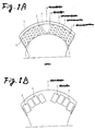
- a plurality of orifice units 6 are provided at intervals in a circumferential direction in a zone corresponding to this annular hardened layer 1b, a plurality of orifices 2 are open in such a manner as to be distributed over a substantially entire area of the hardened layer 1b.
- the orifice units 6 are arranged as follows.
- introducing slots 3 each having a substantially rectangular cross-sectional shape are open substantially radially at intervals in the circumferential direction in the zone corresponding to the annular hardened layer 1b.
- two rows of nozzles 4a and 4b are formed in the longitudinal direction of each introducing slot 3 in the bottom of the introducing slot 3 in such a manner as to communicate with each other so as to form each orifice unit 6, and open ends of the nozzles 4a and 4b are formed as the orifices 2.
- the first row of nozzles 4a and the second row of nozzles 4b of each orifice unit 6 are respectively provided with first nozzle portions 41a and 41b which are small-diameter portions disposed on the introducing slot 3 side at a predetermined depthwise position, as well as second nozzle portions 42a and 42b which are large-diameter portions located on the die opening side.
- each of the second nozzle portions 42a and 42b has a hole diameter d 1 identical to the opening diameter of the orifice 2, while each of the first nozzle portions 41a and 41b has a hole diameter d 2 smaller than the opening diameter of the orifice 2.
- Jackets 7 for temperature regulation provided for preventing the clogging of the nozzles 4a and 4b are each disposed between the first nozzle portions 41a and 41b of mutually adjacent ones of the orifice units 6.
- the first nozzle portions 41a in the first row of nozzles 4a and the first nozzle portions 41b of the second row of nozzles 4b of each orifice unit 6 are respectively disposed eccentrically in mutually opposite directions with respect to the second nozzle portions 42a and 42b, and are thus arranged such that the nozzle pitch P 5 between the adjacent orifice units 6 can be reduced as much as possible while securing the space for disposing the jacket 7 between the first nozzle portions 41a and 41b located at the predetermined depthwise position, thereby making it possible to increase the number of orifices 2 which are open in the discharging side surface 1a of the die.
- a molten resin which flowed into the introducing slots 3 of the orifice units 6 is compressed by the small-diameter first nozzle portions 41a and 41b, then pass through the large-diameter second nozzle portions 42a and 42b, and are extruded uniformly into a cutter box (not shown) from the orifices 2.
- Strands which were extruded into the cutter box are cooled by cooling water which is circulatingly supplied into the cutter box, during which the strands expand and assume diameters larger than the. inside diameter d 1 of the orifice 2.
- both nozzle pitches P 1 and P 2 in two directions inside each orifice unit 6 are preferably set in ranges two to three times as large as the opening diameter d 1 of the orifice 2.
- the first row of nozzles 4a and the second row of nozzles 4b are arranged in a mutually offset manner so as to minimize the interval P 3 between the first row and the second row while securing minimum values of both nozzle pitches P 1 and P 2 .
- the number of orifices is increased by reducing the interval P 3 between the nozzle rows in the above-described manner.
- the jackets 7 for temperature regulation are disposed between the adjacent orifice units 6, as described before.
- the nozzles 4a and 4b of each orifice unit 6 are not provided with the small-diameter first nozzle portions and are constituted only by the second nozzle portions having the same diameter as the opening diameter d 1 of the orifice 2, the nozzle pitch P 4 at a portion where the jacket 7 is disposed must be made large, so that a belt-shaped dead space where the orifices 2 are not present is formed in the discharge side surface la of the die.
- the dead space is reduced and the number of orifices of the die as a whole is increased while securing the space for the jackets 7 which are disposed at a predetermined depth in the orifice unit 6.
- the nozzles 4a and 4b are not provided with the first nozzle portions at the depth of the jackets 7 and are constituted only by the second nozzle portions having the same hole diameter d 1 of the orifice 2
- the nozzle portions each having a diameter smaller than the orifice diameter are provided in the nozzles in an eccentric manner in mutually opposite directions, it is possible to substantially reduce the dead space where the orifices are not present, and increase the number of orifices which are disposed in the die.
- the small-diameter portions i.e., the first nozzle portions, of the nozzles which are arranged in two rows are arrayed eccentrically in mutually opposite directions, these small-diameter portions need not necessarily be eccentric, and may be concentric with the large-diameter portions, i.e., the orifices, if a space necessary for the jackets can be secured in the small-diameter portions of the nozzles.
- first nozzle portions 43a and 43b which are only made eccentric to the second nozzle portions 42a and 42b without providing the small-diameter portions in the nozzles 4a and 4b may be provided, and the jackets 7 for temperature regulation may be disposed at their depthwise position.
- the dead space can be reduced by two times the amount of eccentricity e of the first nozzle portion which is an eccentric portion.
Landscapes
- Engineering & Computer Science (AREA)
- Mechanical Engineering (AREA)
- Manufacturing & Machinery (AREA)
- Processing And Handling Of Plastics And Other Materials For Molding In General (AREA)
- Extrusion Moulding Of Plastics Or The Like (AREA)
Abstract
Description
Claims (6)
- A die for use in a plastic granulating apparatus of an underwater cutting type comprising:a plurality of orifices distributed over a substantially entire area of a predetermined area formed in an annular shape on a discharging side surface of a die base material;a plurality of nozzles formed in said die base material and respectively opening to said orifices;a introducing slot formed in an introducing side surface of said die base material and communicating with said nozzles; anda jacket for temperature regulation disposed in said die base material;wherein, each of said nozzles has a small-diameter portion having a diameter smaller than an opening diameter of said orifice, and said jacket for temperature regulation is disposed at a depthwise position where said small-diameter portion is formed.
- A die for use in a plastic granulating apparatus of an underwater cutting type according to claim 1,
wherein said nozzles are arranged in at least two rows to constitute a orifice unit, and said small-diameter portion of each of said nozzles is formed eccentrically with respect to a large-diameter portion having a diameter identical to the opening diameter of said orifice. - A die for use in a plastic granulating apparatus of an underwater cutting type according to claim 2,
wherein said rows of said nozzles are arranged in a mutually offset manner. - A die for use in a plastic granulating apparatus of an underwater cutting type according to claim 1,
wherein, said predetermined area is constituted by a hardened layer excelling in wear resistance. - A die for use in a plastic granulating apparatus of an underwater cutting type comprising:a plurality of orifices distributed over a substantially entire area of a predetermined area formed in an annular shape on a discharging side surface of a die base material;a plurality of nozzles formed in said die base material and respectively opening to said orifices;a introducing slot formed in an introducing side surface of said die base material and communicating with said nozzles; anda jacket for temperature regulation disposed in said die base material;wherein, each of said nozzles has an eccentric portion formed eccentrically with respect to said orifice, and said jacket for temperature regulation is disposed at a depthwise position where said eccentric portion is formed.
- A die for use in a plastic granulating apparatus of an underwater cutting type according to claim 5,
wherein, said predetermined area is constituted by a hardened layer excelling in wear resistance.
Applications Claiming Priority (2)
| Application Number | Priority Date | Filing Date | Title |
|---|---|---|---|
| JP2000007335 | 2000-01-17 | ||
| JP2000007335A JP4252180B2 (en) | 2000-01-17 | 2000-01-17 | Dies used in underwater cut plastic granulators |
Publications (3)
| Publication Number | Publication Date |
|---|---|
| EP1116570A2 true EP1116570A2 (en) | 2001-07-18 |
| EP1116570A3 EP1116570A3 (en) | 2003-02-05 |
| EP1116570B1 EP1116570B1 (en) | 2005-09-28 |
Family
ID=18535733
Family Applications (1)
| Application Number | Title | Priority Date | Filing Date |
|---|---|---|---|
| EP01100758A Expired - Lifetime EP1116570B1 (en) | 2000-01-17 | 2001-01-12 | Die for use in a plastic granulating apparatus of underwater cutting type |
Country Status (4)
| Country | Link |
|---|---|
| US (1) | US6514062B2 (en) |
| EP (1) | EP1116570B1 (en) |
| JP (1) | JP4252180B2 (en) |
| DE (1) | DE60113571T2 (en) |
Cited By (1)
| Publication number | Priority date | Publication date | Assignee | Title |
|---|---|---|---|---|
| EP1584405A3 (en) * | 2004-03-31 | 2006-11-08 | Kabushiki Kaisha Kobe Seiko Sho (Kobe Steel, Ltd.) | Die Plate |
Families Citing this family (7)
| Publication number | Priority date | Publication date | Assignee | Title |
|---|---|---|---|---|
| US7226553B2 (en) * | 2003-07-30 | 2007-06-05 | E. I. Du Pont De Nemours And Company | Polymer underwater pelletizer apparatus and process incorporating same |
| US7632086B2 (en) * | 2003-10-03 | 2009-12-15 | Exxonmobil Chemical Patents Inc. | Melt fracture reduction |
| JP5801634B2 (en) * | 2011-07-20 | 2015-10-28 | モリマシナリー株式会社 | Ring die for pellet manufacturing equipment |
| JP2014069525A (en) * | 2012-10-01 | 2014-04-21 | Japan Steel Works Ltd:The | Die plate for resin granulation |
| JP6668839B2 (en) * | 2016-03-11 | 2020-03-18 | 日本ポリプロ株式会社 | Pelletizer and method for producing pellets using the same |
| JP6863403B2 (en) * | 2019-05-20 | 2021-04-21 | 日本ポリプロ株式会社 | A pelletizer and a method for producing pellets using the pelletizer. |
| JP7812642B2 (en) * | 2021-11-05 | 2026-02-10 | 株式会社日本製鋼所 | Die, granulating device, and method for producing organic composition pellets |
Family Cites Families (12)
| Publication number | Priority date | Publication date | Assignee | Title |
|---|---|---|---|---|
| US3391657A (en) * | 1961-05-01 | 1968-07-09 | California Pellet Mill Co | Wear compensating die |
| US3287764A (en) * | 1965-06-01 | 1966-11-29 | Black Clawson Co | Plastic pelletizers |
| DE2825288C3 (en) * | 1978-06-09 | 1983-12-29 | Hermann Berstorff Maschinenbau Gmbh, 3000 Hannover | Device for granulating plastic melts and plastic masses |
| JPS59152808A (en) * | 1983-02-22 | 1984-08-31 | Kobe Steel Ltd | Die of underwater cutting granulator |
| US4752196A (en) * | 1986-05-22 | 1988-06-21 | Rogers Tool Works, Inc. | Internally insulated extrusion die |
| DE3642867A1 (en) * | 1986-12-16 | 1988-06-30 | Barmag Barmer Maschf | SPINNING MACHINE |
| US4822546A (en) * | 1987-08-06 | 1989-04-18 | Exxon Chemical Patents Inc. | Die design for underwater pelletization of high flow rate polymers |
| DE3809735C1 (en) * | 1988-03-23 | 1989-06-08 | Werner & Pfleiderer Gmbh, 7000 Stuttgart, De | |
| US5017116A (en) * | 1988-12-29 | 1991-05-21 | Monsanto Company | Spinning pack for wet spinning bicomponent filaments |
| JP3174840B2 (en) * | 1992-03-31 | 2001-06-11 | 日本ジーイープラスチックス株式会社 | Die plate for plastic extruder |
| JP2828601B2 (en) * | 1994-11-18 | 1998-11-25 | 株式会社日本製鋼所 | Granulating dies for synthetic resin and method for producing the same |
| DE19522620C2 (en) * | 1995-06-22 | 1999-03-25 | Krupp Werner & Pfleiderer Gmbh | Process for granulating plastic strands and perforated plate to carry out this process |
-
2000
- 2000-01-17 JP JP2000007335A patent/JP4252180B2/en not_active Expired - Lifetime
-
2001
- 2001-01-11 US US09/757,573 patent/US6514062B2/en not_active Expired - Fee Related
- 2001-01-12 EP EP01100758A patent/EP1116570B1/en not_active Expired - Lifetime
- 2001-01-12 DE DE60113571T patent/DE60113571T2/en not_active Expired - Fee Related
Cited By (4)
| Publication number | Priority date | Publication date | Assignee | Title |
|---|---|---|---|---|
| EP1584405A3 (en) * | 2004-03-31 | 2006-11-08 | Kabushiki Kaisha Kobe Seiko Sho (Kobe Steel, Ltd.) | Die Plate |
| US7311514B2 (en) | 2004-03-31 | 2007-12-25 | Kobe Steel, Ltd. | Die plate |
| CN100393496C (en) * | 2004-03-31 | 2008-06-11 | 株式会社神户制钢所 | a template |
| KR100966200B1 (en) * | 2004-03-31 | 2010-06-25 | 가부시키가이샤 고베 세이코쇼 | Die plate |
Also Published As
| Publication number | Publication date |
|---|---|
| JP2001191325A (en) | 2001-07-17 |
| EP1116570B1 (en) | 2005-09-28 |
| US6514062B2 (en) | 2003-02-04 |
| DE60113571D1 (en) | 2006-02-09 |
| DE60113571T2 (en) | 2006-03-16 |
| JP4252180B2 (en) | 2009-04-08 |
| EP1116570A3 (en) | 2003-02-05 |
| US20010012527A1 (en) | 2001-08-09 |
Similar Documents
| Publication | Publication Date | Title |
|---|---|---|
| US11059200B2 (en) | Honeycomb structure forming die and method of manufacturing honeycomb structure forming die | |
| US5702659A (en) | Honeycomb extrusion die and methods | |
| JPS5838083B2 (en) | Die equipment for extrusion molding of honeycomb structures | |
| EP1116570A2 (en) | Die for use in a plastic granulating apparatus of underwater cutting type | |
| CA2521088A1 (en) | Apparatus and method for forming fibers | |
| US5797444A (en) | Ingot mold for the continuous casting of metals | |
| JPS6322612A (en) | Extruding die, inside of which is heat-insulated | |
| JPH0560404B2 (en) | ||
| US5876804A (en) | Extrusion die for molding honeycomb structure and manufacturing method thereof | |
| EP0275162B1 (en) | Honeycomb structural body extruding die apparatus | |
| US11045867B2 (en) | Continuous casting mold, continuous casting device, and continuous casting method | |
| US6134936A (en) | Mold for heat sink | |
| JPH10315213A (en) | Extrusion equipment for forming honeycomb structures | |
| JP2010264629A (en) | DIE SUPPORT DEVICE AND EXTRUSION DIE HAVING THE SAME | |
| US7524448B2 (en) | Honeycomb extrusion die | |
| DE19651354A1 (en) | Extrusion nozzle- and cutter plate for thermoplastic granulator designed for high productivity | |
| JPH0489224A (en) | Extrusion molding die | |
| JP5686552B2 (en) | Extrusion die apparatus and method for producing extruded material using the same | |
| JP3274111B2 (en) | Dies used for underwater cut type plastic granulator | |
| JP2003220606A (en) | Resin underwater granulation dies | |
| JP3121409B2 (en) | Extrusion die for honeycomb structure | |
| KR20200076776A (en) | Mold Device for Continuous Casting | |
| JP2826426B2 (en) | Granulation dies for resin extruders | |
| JP2609785B2 (en) | Extrusion dies | |
| ITTO20011049A1 (en) | CONTINUOUS EXTRACTION EQUIPMENT FOR FRICTION. |
Legal Events
| Date | Code | Title | Description |
|---|---|---|---|
| PUAI | Public reference made under article 153(3) epc to a published international application that has entered the european phase |
Free format text: ORIGINAL CODE: 0009012 |
|
| AK | Designated contracting states |
Kind code of ref document: A2 Designated state(s): AT BE CH CY DE DK ES FI FR GB GR IE IT LI LU MC NL PT SE TR |
|
| AX | Request for extension of the european patent |
Free format text: AL;LT;LV;MK;RO;SI |
|
| PUAL | Search report despatched |
Free format text: ORIGINAL CODE: 0009013 |
|
| AK | Designated contracting states |
Designated state(s): AT BE CH CY DE DK ES FI FR GB GR IE IT LI LU MC NL PT SE TR |
|
| AX | Request for extension of the european patent |
Extension state: AL LT LV MK RO SI |
|
| 17P | Request for examination filed |
Effective date: 20030711 |
|
| AKX | Designation fees paid |
Designated state(s): DE FR |
|
| 17Q | First examination report despatched |
Effective date: 20030924 |
|
| GRAP | Despatch of communication of intention to grant a patent |
Free format text: ORIGINAL CODE: EPIDOSNIGR1 |
|
| GRAS | Grant fee paid |
Free format text: ORIGINAL CODE: EPIDOSNIGR3 |
|
| GRAA | (expected) grant |
Free format text: ORIGINAL CODE: 0009210 |
|
| AK | Designated contracting states |
Kind code of ref document: B1 Designated state(s): DE FR |
|
| REF | Corresponds to: |
Ref document number: 60113571 Country of ref document: DE Date of ref document: 20060209 Kind code of ref document: P |
|
| ET | Fr: translation filed | ||
| PLBE | No opposition filed within time limit |
Free format text: ORIGINAL CODE: 0009261 |
|
| STAA | Information on the status of an ep patent application or granted ep patent |
Free format text: STATUS: NO OPPOSITION FILED WITHIN TIME LIMIT |
|
| 26N | No opposition filed |
Effective date: 20060629 |
|
| PGFP | Annual fee paid to national office [announced via postgrant information from national office to epo] |
Ref country code: DE Payment date: 20080110 Year of fee payment: 8 |
|
| PGFP | Annual fee paid to national office [announced via postgrant information from national office to epo] |
Ref country code: FR Payment date: 20080108 Year of fee payment: 8 |
|
| PG25 | Lapsed in a contracting state [announced via postgrant information from national office to epo] |
Ref country code: DE Free format text: LAPSE BECAUSE OF NON-PAYMENT OF DUE FEES Effective date: 20090801 |
|
| REG | Reference to a national code |
Ref country code: FR Ref legal event code: ST Effective date: 20091030 |
|
| PG25 | Lapsed in a contracting state [announced via postgrant information from national office to epo] |
Ref country code: FR Free format text: LAPSE BECAUSE OF NON-PAYMENT OF DUE FEES Effective date: 20090202 |