EP1116006B1 - Head for the linear dimension checking of mechanical pieces - Google Patents
Head for the linear dimension checking of mechanical pieces Download PDFInfo
- Publication number
- EP1116006B1 EP1116006B1 EP99942926A EP99942926A EP1116006B1 EP 1116006 B1 EP1116006 B1 EP 1116006B1 EP 99942926 A EP99942926 A EP 99942926A EP 99942926 A EP99942926 A EP 99942926A EP 1116006 B1 EP1116006 B1 EP 1116006B1
- Authority
- EP
- European Patent Office
- Prior art keywords
- head according
- microswitch
- movable
- wire
- casing
- Prior art date
- Legal status (The legal status is an assumption and is not a legal conclusion. Google has not performed a legal analysis and makes no representation as to the accuracy of the status listed.)
- Expired - Lifetime
Links
Images




Classifications
-
- G—PHYSICS
- G01—MEASURING; TESTING
- G01B—MEASURING LENGTH, THICKNESS OR SIMILAR LINEAR DIMENSIONS; MEASURING ANGLES; MEASURING AREAS; MEASURING IRREGULARITIES OF SURFACES OR CONTOURS
- G01B5/00—Measuring arrangements characterised by the use of mechanical techniques
- G01B5/004—Measuring arrangements characterised by the use of mechanical techniques for measuring coordinates of points
- G01B5/008—Measuring arrangements characterised by the use of mechanical techniques for measuring coordinates of points using coordinate measuring machines
- G01B5/012—Contact-making feeler heads therefor
Definitions
- the present invention relates to a head for the linear dimension checking of mechanical pieces, including a casing, that defines a longitudinal geometric axis, an arm-set, movable with respect to the casing, a feeler, coupled to the movable arm-set, for touching the piece to be checked, a bias device, arranged between the casing and the movable arm-set, a detecting device, coupled to the casing, including a movable element, and a transmission device, between the movable arm-set and the movable element of the detecting device, including a wire, substantially rigid in said longitudinal direction but flexible in the directions perpendicular to the longitudinal direction, the wire having a first end coupled to the movable arm-set and a second end for cooperating with the movable element of the detecting device.
- the repeatability errors be as small as possible, considerably smaller than 1 ⁇ m.
- the repeatability errors are mainly due to the effects of frictions among reciprocally moving parts, to shape errors of elements of the head, and to vibrations due to shock waves or other dynamic phenomena.
- a detecting device disclosed in US-A-5299360 includes a microswitch with a stem having an end adapted for contacting the movable arm-set. This contact may involve slidings and thus repeatability errors. Moreover, as the stem of the microswitch is not constrained with respect to rotations about its axis, and it is possible that there may be errors in the shape of the stem, other repeatability errors may consequently possibly arise.
- a measuring probe with a housing, that defines a frusto-conical cavity, a position transducer measuring device fixed at the interior of the housing, and a movable arm-set with shaped portions for providing contact and a frusto-conical portion for cooperating with the frusto-conical cavity of the housing.
- the measuring device includes a movable element coupled to an end of a wire, axially rigid but flexible in transversal directions. The other end of the wire is connected to the movable arm-set.
- the measuring device includes means, not shown, that presumably consist of an internal spring, that, by means of the movable element and the wire, urge the frusto-conical portion of the movable arm-set towards the frusto-conical cavity of the housing.
- the wire is subject to a compressive stress of a considerable entity, owing to the fact that it has to apply force for causing contact between the movable portion the arm-set and the cavity of the housing. Consequently, problems arise insofar as the dimensions of the section of the wire are concerned, because of the contrasting requirements of providing resistance to a considerable compressive stress on the one hand and achieving good lateral flexibility on the other. Moreover, even the frictional forces acting on the wire necessarily have relatively high values.
- a tracer head including a wire (or rod spring) and the other features according to the technical field of the present invention is shown in US-A-4187614.
- This head includes a stylus adapted to touch a model surface and a tracer shaft carrying the stylus.
- the shaft includes a rigid portion and a rod spring portion, respectively coupled to a casing by means of a first and a second mutually parallel planar springs. Axial and radial movements of the stylus are transmitted to an axial and, thanks to the bending of the rod spring, two radial displacement detectors coupled to the casing.
- the connection of the shaft by means of the two planar springs causes a compression action on the rod spring, in particular when the stylus touches the model surface, with consequent problems, e.g. in connection with the choice of its sectional dimensions, as cited above with reference to the article "Multi-directional probe".
- Object of the present invention is to provide a checking head in which the component of the repeatability error due to the detecting device is particularly small.
- a checking head of the herein described type in which the bias device is arranged in such a way that it urges the movable arm-set into contact with the casing and does not apply a compressive stress onto the wire of the transmission device.
- the invention enables to achieve negligible frictional forces in the transmission device and in the detecting device, avoid problems insofar as the design sizes of the transmission device are concerned and, in conclusion, considerably improve the head repeatability.
- the contact detecting head shown in figure 1 includes a casing 1, with a substantially cylindrical shape, consisting of two superimposed portions 2 and 3, coupled by means of a threaded coupling, that define a longitudinal geometric axis.
- portion 3 In the lower part of portion 3 there is a seat 4 with a substantially frusto-conical surface.
- the movable arm-set 5 of the head includes a reference element 6 with a surface having substantially the shape of a spherical zone for engaging with seat 4, a hollow portion 8, with a substantially cylindrical shape, integral with the reference element 6, and an upper flange 10, integral with the hollow portion 8, that has an annular portion 11 protruding downwards.
- annular portion 11 is at a distance of a few micrometers from a corresponding stationary annular surface 12 formed in a plane recess of portion 3.
- movable arm-set 5 includes an arm 14 with a feeler 15.
- a helical spring 19 has its ends abutting against two plane surfaces formed in reference element 6 and in an abutment element 20 integral with portion 3 of casing 1 and urges the spherical part of reference element 6 towards seat 4.
- the herein described coupling between movable arm-set 5 and casing 1 is adapted to eliminate three degrees of freedom of movable arm-set 5.
- Another degree of freedom, that relates to rotations of movable arm-set 5 about the longitudinal geometric axis defined by casing 1, is eliminated by a metal bellows 21, that houses spring 19 at the interior and has its ends secured to the plane surface of reference element 6 and to another transversal surface of portion 3.
- feeler 15 The contact occurring between feeler 15 and a piece is detected, subsequently to a determinate pre-stroke in a longitudinal direction or, in the case of displacements of feeler 15 in a transversal direction, at a determinate angle between the longitudinal geometric axis of casing 1 and the geometric axis of arm 14, by means of a detecting device that includes a microswitch 23.
- the microswitch 23 includes a casing 24 with an insulating, cylindrical element 25 that houses a spring 26 for urging a movable element, more specifically a small ball 27, made of electrically conducting material, into contact with two small bars 29 and 30, also made of electrically conducting material, secured to insulating element 25 at a lower base of casing 24.
- microswitch 23 When small ball 27 contacts bars 29 and 30, microswitch 23 is closed, whereas when ball 27 disengages from at least one of bars 29 and 30, microswitch 23 opens.
- An external circuit is connected to bars 29 and 30 by means of conductors, not shown in the drawings, that traverse a longitudinal opening 33.
- microswitch 23 includes a stem 35, axially guided by means of two sapphire bushings 36 fixed to casing 24 near contact bars 29 and 30.
- the lower end of stem 35 is secured at the top of a coupling element 37 that has its lower part secured to the upper end of a flexible wire 38.
- the lower end of wire 38 is secured, by means of an insulating bushing 39, to a coupling and adjustment, threaded dowel 40 , that is centrally coupled, by means of a frictional coupling, to the upper part of reference element 6.
- the wire 38 is made of spring steel and can be, for example, 20 mm long and have a diameter of 0.4-0.5 mm.
- feeler 15 When feeler 15 is not subject to contact forces with a piece, the upper end of stem 35 is at a short distance from ball 27.
- wire 38 Upon contact with the piece, wire 38 transmits an upward displacement to stem 35, and the latter contacts-after a determined amount of pre-stroke - small ball 27 and causes it to disengage from bars 29 and 30, overcoming the force applied by spring 26, that is relatively small with respect to that applied by spring 19.
- the latter is rigid with respect to axial forces, while can deflect in a transversal direction because of the transversal forces that are generated as a consequence of contact occurring between feeler 15 and the piece in a transversal direction.
- microswitch 23 and in the coupling device are low in number and value.
- the contribution to the repeatability error of the head provided by microswitch 23 and the coupling device is relatively small (in the range of 0.05-0.1 ⁇ m).
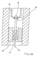
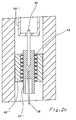
- Figures 2a, 2b and 2c show how, in order to guide in a more accurate way axial displacements of stem 35 - by limiting the length of its free portion - and to dampen possible vibrations of wire 38, different (or supplemental) guide devices are provided.
- a guide 42 in addition to one of the two bushings 36 there can be foreseen a guide 42, made of antifriction material, at the interior of which coupling element 37 slides.
- Guide 42 is coupled to casing 24.
- Figure 2b shows a different coupling element 37' including a substantially spherical surface, that slides in a guide 42' coupled to portion 2 of the casing 1 .
- Figure 2c shows a substantially cylindrical coupling element 37" housed in a guide 42" coupled to portion 2.
- a ball bearing 43 is arranged between the coupling element 37" and the guide 42", and no bushings 36 are fixed to the casing 24.
- the guide devices according to figures 2b and 2c guarantee a guiding action involving particularly low friction and stresses.
- head shown in figure 1 can be modified in such a way as to eliminate stem 35 , so that the upper end of wire 38 is free and can directly act on small ball 27.
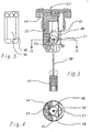
- microswitch 23' there is not foreseen an axial thrust spring.
- Wire 38' has its upper end directly secured to small ball 27'.
- the bars 45 and 46 are arranged parallel with respect to the longitudinal geometric axis and side by side in a transversal direction.
- a shaped element 49 made from insulating material (for example, ceramic) is also internally secured to insulating element 25' of microswitch 23', substantially at an intermediate position between conducting bars 45 and 46, and defines an abutment surface.
- An elastic thin plate 48 has its upper end clamped to insulating element 25', and its free end specifically shaped for urging small ball 27' towards bars 45 and 46 in such a way as to close microswitch 23'.
- thin plate 48 has a window 50 and the end open.
- microswitch 23' is set by operating threaded dowel 40, as in the embodiment shown in figure 1.
- movable ball 27' Upon contact occurring between the feeler and the piece, and the subsequent displacing of wire 38' and thin plate 48, movable ball 27' is urged upwards, contacts shaped element 49 and disengages from at least one of stationary bars 45 and 46, thereby opening microswitch 23'. Then ball 27' slides on shaped element 49, urged towards the latter by thin plate 48, as shown with dashed lines in figure 3.
- wire 38' does not undergo any compressive stress and, indeed, can undergo a slight tractive force.
- Figures 6 and 7 show a microswitch 23'' with some variants with respect to the head of figures 3 to 5. More specifically, conducting bars 45' and 46' are arranged in a direction that is inclined with respect to the longitudinal geometric axis. Moreover, a flat element or small plate 44 made of rigid, hard material, like ceramic, is internally fixed to insulating element 25'' of casing 24'' and defines a plane abutment surface arranged in the direction of the longitudinal geometric axis.
- a head including microswitch 23'' is substantially alike that described with reference to figures 3, 4 and 5. More specifically, upon contact occurring between the feeler and the piece, the subsequent displacement of wire 38' and the thrust of thin plate 48, movable ball 27' displaces in the inclined direction defined by stationary bars 45' and 46' until it touches the plane surface of plate 44 and disengages from at least one of the formerly mentioned bars 45' and 46', thereby opening microswitch 23''. Then ball 27' slides on the plane abutment surface of plate 44, urged towards it by thin plate 48, as shown with dashed lines in figure 6.
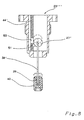
- Figure 8 shows a microswitch 23''' with further variants with respect to the embodiments illustrated in figures from 3 to 7.
- small ball 27' is made of ferromagnetic material and, instead of being urged by an elastic thin plate towards the stationary contacts, consisting of two small balls (only one, 51, is shown in the figure), it is attracted towards them and towards the plane abutment surface of an insulating plate 44' by a magnetic disk, in particular a permanent magnet 53, set in plate 44'.
- the structure of the measuring head shown in figure 9 is to a great extent similar to that of the head of figure 1, except for the detecting device that includes a position transducer and the transmission wire that is connected in a different way.
- wire 38'' is coupled to adjustment dowel 40 as described with reference to wire 38 shown in figure 1.
- the upper end of wire 38'' is locked in a hole of a substantially cylindrical support 55 that carries in its central part a magnetic core 56, axially movable within electric windings 57 of an inductive position transducer.
- the windings 57 are formed in slots of a spool 58 that has an axial hole with a surface that acts as a guide for support 55 and thus for wire 38''.
- wire 38'' does not undergo significant compressive stresses or tractive forces.
- the invention enables to achieve probes suitable for operating in a workshop environment, e.g. for applications in lathes and machining centers, with repeatability errors smaller than 0.2-0.3 ⁇ m.
Landscapes
- Physics & Mathematics (AREA)
- General Physics & Mathematics (AREA)
- Measurement Of Length, Angles, Or The Like Using Electric Or Magnetic Means (AREA)
- Length Measuring Devices With Unspecified Measuring Means (AREA)
- A Measuring Device Byusing Mechanical Method (AREA)
- Supporting Of Heads In Record-Carrier Devices (AREA)
- Adjustment Of The Magnetic Head Position Track Following On Tapes (AREA)
- Magnetic Heads (AREA)
Abstract
Description
Claims (24)
- A head for the linear dimension checking of mechanical pieces, including a casing (1), that defines a longitudinal geometric axis, an arm-set (5), movable with respect to the casing, a feeler (15), coupled to the movable arm-set (5) for touching the piece to be checked, a bias device (19), arranged between the casing (1), and the movable arm-set (5), a detecting device (23;23';23'';23''';56,57), coupled to the casing (1), including a movable element (27;27';56), and a transmission device (35,38;38';38''), between the movable arm-set (5) and the movable element (27;27';56) of the detecting device, including a wire (36;38';38''), substantially rigid in said longitudinal direction but flexible in the directions perpendicular to the longitudinal direction, the wire (38;38';38'') having a first end coupled to the movable arm-set (5) and a second end for cooperating with the movable element (27;27';56) of the detecting device, characterized in that the bias device (19) is arranged in such a way that it urges the movable arm-set (5) into contact with the casing (1) and does not apply a compressive stress onto the wire (38) of the transmission device.
- The head according to claim 1, for detecting contact between said feeler and the piece, wherein said detecting device includes a microswitch (23;23';23'';23''') with two stationary elements (29,30;45,46;45',46';51) made of electrically conducting material, the movable element (27;27') of the detecting device also being made of electrically conducting material and being adapted for contacting said two stationary elements.
- The head according to claim 2, wherein said microswitch (23) includes a thrust spring (26) acting on said movable element (27), the latter having a spherical shape, said second end of the wire (38) being adapted for contacting said movable element of the microswitch.
- The head according to claim 2, wherein said microswitch (23) includes a thrust spring (26) acting on said movable element (27), the latter having a spherical shape, the microswitch including a movable stem (35) and a device (36;42;42';42") for guiding the stem in the direction of said longitudinal geometric axis, said stem having an end for contacting said movable element of the microswitch and the other end secured to said second end of the wire.
- The head according to claim 4, wherein said wire (38) is made of steel and the second end of the wire is secured to the stem (35) of the microswitch by means of a coupling element (37;37';37").
- The head according to claim 5, wherein said device for guiding the stem includes at least one bushing (36), arranged near said stationary elements (29,30) and adapted to cooperate with the stem (35).
- The head according to claim 5 or claim 6, wherein said device for guiding the stem includes a guide (42;42';42") adapted to cooperate with said coupling element (37;37' ;37").
- The head according to claim 7, wherein said coupling element (37') includes a substantially spherical surface adapted to cooperate with said guide (42').
- The head according to claim 7, wherein said device for guiding the stem includes a ball bearing (43) arranged between the coupling element (37") and the guide (42").
- The head according to one of claims from 1 to 9, wherein said first end of the wire (38;38' ;38'') is secured to the movable arm-set (5) by means of a coupling device (40) for enabling adjustments in the direction of said longitudinal geometric axis.
- The head according to claim 2, wherein said microswitch (23';23'';23''') includes a device (48;53) for applying to the movable element (27') a force in a direction substantially transversal with respect to said longitudinal axis for bringing the movable element into contact with the two stationary elements (45,46;45',46';51), said second end of the wire (38') being secured to the movable element (27') of the microswitch (23' ;23'' ;23''').
- The head according to claim 11, wherein said microswitch (23';23'';23''') includes at least a stationary abutment surface (49;44;44'), the movable element (27') being adapted for touching - upon contact of the feeler (15) with the piece - said abutment surface and disengaging from at least one of the two stationary elements (45,46;45',46';51).
- The head according to claim 12, wherein said two stationary elements (45,46) have substantially rotational symmetry and are arranged adjacent in a transversal direction, and substantially parallel with respect to said longitudinal geometric axis.
- The head according to claim 13, wherein the microswitch (23') includes a stationary, shaped element (49) made from insulating material that defines said abutment surface.
- The head according to claim 12, wherein said two stationary elements (45',46') have substantially rotational symmetry and are arranged adjacent in a transversal direction, and substantially parallel with respect to each other in a direction that is inclined with respect to said longitudinal geometric axis.
- The head according to claim 12, wherein said two stationary elements (51) have a substantially spherical shape and are arranged adjacent in a transversal direction.
- The head according to claim 15 or claim 16, wherein the microswitch (23'';23''') includes a flat element (44;44') that defines said abutment surface, the abutment surface being substantially plane and arranged in the direction of said longitudinal geometric axis.
- The head according to one of claims from 11 to 17, wherein said device for applying a force to the movable element of the microswitch includes an elastic element (48).
- The head according to one of claims from 11 to 17, wherein said device (53) for applying a force to the movable element of the microswitch applies a magnetic attractive force.
- The head according to claim 1, wherein said detecting device includes a position transducer (56,57) and the second end of the wire (38'') is secured to the movable element (56) of the detecting device.
- The head according to claim 20, wherein said position transducer includes stationary windings (57) and the movable element of the transducer includes a magnetic core (56).
- The head according to claim 21, wherein said position transducer includes a support (55) and a spool (58) that defines an axial hole for housing and guiding the support (55), the magnetic core (56) and the stationary windings (57) being coupled to said support (55) and spool (58), respectively.
- The head according to any one of the previous claims, wherein said movable arm-set and said casing include a constraining system substantially of the cone-ball type (4,6) and two facing annular surfaces (11,12) for providing a substantially point-to-point contact.
- The head according to claim 23, wherein there is foreseen - between said movable arm-set and said casing - a further constraining system (21) for preventing rotations of the movable arm-set about said longitudinal geometric axis.
Applications Claiming Priority (3)
| Application Number | Priority Date | Filing Date | Title |
|---|---|---|---|
| IT1998BO000538A IT1305536B1 (en) | 1998-09-21 | 1998-09-21 | HEAD FOR THE CONTROL OF LINEAR DIMENSIONS OF MECHANICAL PIECES |
| ITBO980538 | 1998-09-21 | ||
| PCT/EP1999/006305 WO2000017602A1 (en) | 1998-09-21 | 1999-08-27 | Head for the linear dimension checking of mechanical pieces |
Publications (2)
| Publication Number | Publication Date |
|---|---|
| EP1116006A1 EP1116006A1 (en) | 2001-07-18 |
| EP1116006B1 true EP1116006B1 (en) | 2003-02-26 |
Family
ID=11343410
Family Applications (1)
| Application Number | Title | Priority Date | Filing Date |
|---|---|---|---|
| EP99942926A Expired - Lifetime EP1116006B1 (en) | 1998-09-21 | 1999-08-27 | Head for the linear dimension checking of mechanical pieces |
Country Status (8)
| Country | Link |
|---|---|
| US (1) | US6526672B1 (en) |
| EP (1) | EP1116006B1 (en) |
| AT (1) | ATE233395T1 (en) |
| AU (1) | AU5625299A (en) |
| DE (1) | DE69905593T2 (en) |
| ES (1) | ES2191454T3 (en) |
| IT (1) | IT1305536B1 (en) |
| WO (1) | WO2000017602A1 (en) |
Families Citing this family (20)
| Publication number | Priority date | Publication date | Assignee | Title |
|---|---|---|---|---|
| CA2414250A1 (en) * | 2001-12-21 | 2003-06-21 | Magna International Inc. | Electronic measuring device |
| GB0207912D0 (en) * | 2002-04-05 | 2002-05-15 | Renishaw Plc | Kinematic coupling |
| DE10262188B4 (en) * | 2002-08-29 | 2010-05-12 | Blum-Novotest Gmbh | Multidirectional probe |
| ITBO20020628A1 (en) * | 2002-10-07 | 2004-04-08 | Marposs Spa | PROBE PROBE |
| DE60308632T2 (en) * | 2003-01-29 | 2007-08-23 | Tesa Sa | Stylus with adjustable orientation |
| US20050055124A1 (en) * | 2003-09-04 | 2005-03-10 | Cym Graphics Inc. | Positioning probe and its control system |
| US7168179B2 (en) | 2003-09-29 | 2007-01-30 | Marposs Societa ' Per Azioni | Touch probe comprising a switch with contacts protected by inert gas |
| DE102005015890B4 (en) * | 2005-02-24 | 2007-05-03 | Wolfgang Madlener | feeler |
| WO2007088570A2 (en) * | 2006-02-02 | 2007-08-09 | Metris Ipr Nv | Probe for gauging machines |
| US7797851B2 (en) * | 2006-05-18 | 2010-09-21 | Panasonic Corporation | Shape measurement device probe and shape measurement device |
| DE102012216159B4 (en) * | 2012-09-12 | 2016-04-28 | Secopta Gmbh | Probe tip for a spectrometer |
| DE102013001457A1 (en) * | 2013-01-28 | 2014-07-31 | Blum-Novotest Gmbh | In a workpiece processing machine to be recorded temperature-compensated probe and method for temperature compensation of a probe |
| US10866080B2 (en) * | 2018-11-01 | 2020-12-15 | Mitutoyo Corporation | Inductive position detection configuration for indicating a measurement device stylus position |
| US11543899B2 (en) | 2018-11-01 | 2023-01-03 | Mitutoyo Corporation | Inductive position detection configuration for indicating a measurement device stylus position and including coil misalignment compensation |
| US11740064B2 (en) | 2018-11-01 | 2023-08-29 | Mitutoyo Corporation | Inductive position detection configuration for indicating a measurement device stylus position |
| US11644298B2 (en) | 2018-11-01 | 2023-05-09 | Mitutoyo Corporation | Inductive position detection configuration for indicating a measurement device stylus position |
| US10914570B2 (en) * | 2018-11-01 | 2021-02-09 | Mitutoyo Corporation | Inductive position detection configuration for indicating a measurement device stylus position |
| US11644299B2 (en) | 2020-12-31 | 2023-05-09 | Mitutoyo Corporation | Inductive position sensor signal gain control for coordinate measuring machine probe |
| US11713956B2 (en) | 2021-12-22 | 2023-08-01 | Mitutoyo Corporation | Shielding for sensor configuration and alignment of coordinate measuring machine probe |
| US11733021B2 (en) | 2021-12-22 | 2023-08-22 | Mitutoyo Corporation | Modular configuration for coordinate measuring machine probe |
Family Cites Families (11)
| Publication number | Priority date | Publication date | Assignee | Title |
|---|---|---|---|---|
| US4187614A (en) * | 1978-08-04 | 1980-02-12 | Mitsubishi Jukogyo Kabushiki Kaisha | Tracer head |
| DE3234470C2 (en) * | 1982-09-17 | 1985-11-21 | Dr. Johannes Heidenhain Gmbh, 8225 Traunreut | Multi-coordinate probe |
| GB2208934B (en) | 1987-08-24 | 1991-05-15 | Mitutoyo Corp | Surface contour measuring tracer |
| IT1238266B (en) * | 1990-03-06 | 1993-07-12 | Marposs Spa | HEAD FOR THE CONTROL OF LINEAR DIMENSIONS OF PIECES. |
| GB9116044D0 (en) * | 1991-07-24 | 1991-09-11 | Nat Res Dev | Probes |
| DE4228018C2 (en) * | 1992-08-24 | 1994-11-24 | Haff & Schneider Werkzeug Und | Multi-coordinate touch probe |
| IT1263452B (en) * | 1993-07-01 | 1996-08-05 | Marposs Spa | BUFFER COMPARATOR. |
| JPH08509299A (en) * | 1994-02-18 | 1996-10-01 | レニショウ パブリック リミテッド カンパニー | Measuring probe |
| GB9423176D0 (en) * | 1994-11-17 | 1995-01-04 | Renishaw Plc | Touch probe |
| DE59509004D1 (en) * | 1995-03-10 | 2001-03-08 | Heidenhain Gmbh Dr Johannes | Multi-coordinate probe with the same deflections |
| EP1024341A1 (en) * | 1999-01-29 | 2000-08-02 | Renishaw plc | Probe with vibration damped stylus |
-
1998
- 1998-09-21 IT IT1998BO000538A patent/IT1305536B1/en active
-
1999
- 1999-08-27 DE DE69905593T patent/DE69905593T2/en not_active Expired - Lifetime
- 1999-08-27 WO PCT/EP1999/006305 patent/WO2000017602A1/en not_active Ceased
- 1999-08-27 AU AU56252/99A patent/AU5625299A/en not_active Abandoned
- 1999-08-27 AT AT99942926T patent/ATE233395T1/en not_active IP Right Cessation
- 1999-08-27 EP EP99942926A patent/EP1116006B1/en not_active Expired - Lifetime
- 1999-08-27 US US09/762,190 patent/US6526672B1/en not_active Expired - Fee Related
- 1999-08-27 ES ES99942926T patent/ES2191454T3/en not_active Expired - Lifetime
Also Published As
| Publication number | Publication date |
|---|---|
| DE69905593D1 (en) | 2003-04-03 |
| DE69905593T2 (en) | 2003-11-27 |
| WO2000017602A1 (en) | 2000-03-30 |
| EP1116006A1 (en) | 2001-07-18 |
| ES2191454T3 (en) | 2003-09-01 |
| US6526672B1 (en) | 2003-03-04 |
| ATE233395T1 (en) | 2003-03-15 |
| ITBO980538A1 (en) | 2000-03-21 |
| IT1305536B1 (en) | 2001-05-09 |
| AU5625299A (en) | 2000-04-10 |
Similar Documents
| Publication | Publication Date | Title |
|---|---|---|
| US6526672B1 (en) | Head for the linear dimension checking of mechanical pieces | |
| JP4405079B2 (en) | Head, apparatus and method for inspection of machine part length dimension | |
| US6578283B2 (en) | Position transducer | |
| WO1992012438A1 (en) | Magnetic sensor and structure of its mounting | |
| JP4266416B2 (en) | Test equipment | |
| KR950009066B1 (en) | Probe for checking linerr dimensions | |
| US4503616A (en) | Parallel motion displacement transducers | |
| CN108489441A (en) | A kind of contact-type 3 D spotting scaming gauge head | |
| JP2003207330A (en) | Trigger probe and its assembling method | |
| JP4304156B2 (en) | A touch probe comprising a transmission device and a spring that urges the transmission device to press against the guide surface | |
| EP1244893B1 (en) | Axial movement linear gauging head | |
| US4899577A (en) | Device for a hardness measuring instrument | |
| US6222436B1 (en) | Axial movement linear gauging head | |
| US7168179B2 (en) | Touch probe comprising a switch with contacts protected by inert gas | |
| CN207963827U (en) | A kind of contact-type 3 D spotting scaming gauge head | |
| EP3123107B1 (en) | Apparatus for checking dimensions and shape of a mechanical piece | |
| TW513554B (en) | Multi-coordinate probe measurement appliance | |
| JPH10253310A (en) | Contact type displacement measuring device | |
| CN114838929A (en) | Electromagnetic brake testing arrangement of adjustable position appearance | |
| CN119644212A (en) | Solenoid valve electromagnetic force measuring device | |
| SU1565687A1 (en) | Tactile pickup | |
| JPH04344401A (en) | Variable inductance converter | |
| KR19980064979A (en) | Head assembly of electronic measuring instruments for measuring the outer and inner diameters of workpieces | |
| JPH02250752A (en) | Positioning stage | |
| JPH01263501A (en) | Feel probe |
Legal Events
| Date | Code | Title | Description |
|---|---|---|---|
| PUAI | Public reference made under article 153(3) epc to a published international application that has entered the european phase |
Free format text: ORIGINAL CODE: 0009012 |
|
| 17P | Request for examination filed |
Effective date: 20010322 |
|
| AK | Designated contracting states |
Kind code of ref document: A1 Designated state(s): AT BE CH CY DE DK ES FI FR GB GR IE IT LI LU MC NL PT SE |
|
| AX | Request for extension of the european patent |
Free format text: AL;LT;LV;MK;RO;SI |
|
| GRAG | Despatch of communication of intention to grant |
Free format text: ORIGINAL CODE: EPIDOS AGRA |
|
| 17Q | First examination report despatched |
Effective date: 20020510 |
|
| GRAG | Despatch of communication of intention to grant |
Free format text: ORIGINAL CODE: EPIDOS AGRA |
|
| GRAG | Despatch of communication of intention to grant |
Free format text: ORIGINAL CODE: EPIDOS AGRA |
|
| GRAH | Despatch of communication of intention to grant a patent |
Free format text: ORIGINAL CODE: EPIDOS IGRA |
|
| GRAH | Despatch of communication of intention to grant a patent |
Free format text: ORIGINAL CODE: EPIDOS IGRA |
|
| GRAA | (expected) grant |
Free format text: ORIGINAL CODE: 0009210 |
|
| AK | Designated contracting states |
Designated state(s): AT BE CH CY DE DK ES FI FR GB GR IE IT LI LU MC NL PT SE |
|
| PG25 | Lapsed in a contracting state [announced via postgrant information from national office to epo] |
Ref country code: NL Free format text: LAPSE BECAUSE OF FAILURE TO SUBMIT A TRANSLATION OF THE DESCRIPTION OR TO PAY THE FEE WITHIN THE PRESCRIBED TIME-LIMIT Effective date: 20030226 Ref country code: LI Free format text: LAPSE BECAUSE OF FAILURE TO SUBMIT A TRANSLATION OF THE DESCRIPTION OR TO PAY THE FEE WITHIN THE PRESCRIBED TIME-LIMIT Effective date: 20030226 Ref country code: GR Free format text: LAPSE BECAUSE OF FAILURE TO SUBMIT A TRANSLATION OF THE DESCRIPTION OR TO PAY THE FEE WITHIN THE PRESCRIBED TIME-LIMIT Effective date: 20030226 Ref country code: FI Free format text: LAPSE BECAUSE OF FAILURE TO SUBMIT A TRANSLATION OF THE DESCRIPTION OR TO PAY THE FEE WITHIN THE PRESCRIBED TIME-LIMIT Effective date: 20030226 Ref country code: CH Free format text: LAPSE BECAUSE OF FAILURE TO SUBMIT A TRANSLATION OF THE DESCRIPTION OR TO PAY THE FEE WITHIN THE PRESCRIBED TIME-LIMIT Effective date: 20030226 Ref country code: BE Free format text: LAPSE BECAUSE OF FAILURE TO SUBMIT A TRANSLATION OF THE DESCRIPTION OR TO PAY THE FEE WITHIN THE PRESCRIBED TIME-LIMIT Effective date: 20030226 Ref country code: AT Free format text: LAPSE BECAUSE OF FAILURE TO SUBMIT A TRANSLATION OF THE DESCRIPTION OR TO PAY THE FEE WITHIN THE PRESCRIBED TIME-LIMIT Effective date: 20030226 |
|
| REG | Reference to a national code |
Ref country code: GB Ref legal event code: FG4D |
|
| REG | Reference to a national code |
Ref country code: CH Ref legal event code: EP |
|
| REG | Reference to a national code |
Ref country code: IE Ref legal event code: FG4D |
|
| REF | Corresponds to: |
Ref document number: 69905593 Country of ref document: DE Date of ref document: 20030403 Kind code of ref document: P |
|
| PG25 | Lapsed in a contracting state [announced via postgrant information from national office to epo] |
Ref country code: SE Free format text: LAPSE BECAUSE OF FAILURE TO SUBMIT A TRANSLATION OF THE DESCRIPTION OR TO PAY THE FEE WITHIN THE PRESCRIBED TIME-LIMIT Effective date: 20030526 Ref country code: PT Free format text: LAPSE BECAUSE OF FAILURE TO SUBMIT A TRANSLATION OF THE DESCRIPTION OR TO PAY THE FEE WITHIN THE PRESCRIBED TIME-LIMIT Effective date: 20030526 Ref country code: DK Free format text: LAPSE BECAUSE OF FAILURE TO SUBMIT A TRANSLATION OF THE DESCRIPTION OR TO PAY THE FEE WITHIN THE PRESCRIBED TIME-LIMIT Effective date: 20030526 |
|
| NLV1 | Nl: lapsed or annulled due to failure to fulfill the requirements of art. 29p and 29m of the patents act | ||
| PG25 | Lapsed in a contracting state [announced via postgrant information from national office to epo] |
Ref country code: LU Free format text: LAPSE BECAUSE OF NON-PAYMENT OF DUE FEES Effective date: 20030827 Ref country code: IE Free format text: LAPSE BECAUSE OF NON-PAYMENT OF DUE FEES Effective date: 20030827 Ref country code: CY Free format text: LAPSE BECAUSE OF FAILURE TO SUBMIT A TRANSLATION OF THE DESCRIPTION OR TO PAY THE FEE WITHIN THE PRESCRIBED TIME-LIMIT Effective date: 20030827 |
|
| PG25 | Lapsed in a contracting state [announced via postgrant information from national office to epo] |
Ref country code: MC Free format text: LAPSE BECAUSE OF NON-PAYMENT OF DUE FEES Effective date: 20030831 |
|
| REG | Reference to a national code |
Ref country code: ES Ref legal event code: FG2A Ref document number: 2191454 Country of ref document: ES Kind code of ref document: T3 |
|
| ET | Fr: translation filed | ||
| PLBE | No opposition filed within time limit |
Free format text: ORIGINAL CODE: 0009261 |
|
| STAA | Information on the status of an ep patent application or granted ep patent |
Free format text: STATUS: NO OPPOSITION FILED WITHIN TIME LIMIT |
|
| 26N | No opposition filed |
Effective date: 20031127 |
|
| REG | Reference to a national code |
Ref country code: IE Ref legal event code: MM4A |
|
| PGFP | Annual fee paid to national office [announced via postgrant information from national office to epo] |
Ref country code: ES Payment date: 20050804 Year of fee payment: 7 |
|
| PGFP | Annual fee paid to national office [announced via postgrant information from national office to epo] |
Ref country code: FR Payment date: 20050810 Year of fee payment: 7 |
|
| REG | Reference to a national code |
Ref country code: FR Ref legal event code: ST Effective date: 20070430 |
|
| REG | Reference to a national code |
Ref country code: ES Ref legal event code: FD2A Effective date: 20060828 |
|
| PG25 | Lapsed in a contracting state [announced via postgrant information from national office to epo] |
Ref country code: ES Free format text: LAPSE BECAUSE OF NON-PAYMENT OF DUE FEES Effective date: 20060828 |
|
| PG25 | Lapsed in a contracting state [announced via postgrant information from national office to epo] |
Ref country code: FR Free format text: LAPSE BECAUSE OF NON-PAYMENT OF DUE FEES Effective date: 20060831 |
|
| REG | Reference to a national code |
Ref country code: GB Ref legal event code: 732E Free format text: REGISTERED BETWEEN 20141002 AND 20141008 |
|
| PGFP | Annual fee paid to national office [announced via postgrant information from national office to epo] |
Ref country code: DE Payment date: 20180831 Year of fee payment: 20 Ref country code: IT Payment date: 20180831 Year of fee payment: 20 |
|
| PGFP | Annual fee paid to national office [announced via postgrant information from national office to epo] |
Ref country code: GB Payment date: 20180823 Year of fee payment: 20 |
|
| REG | Reference to a national code |
Ref country code: DE Ref legal event code: R071 Ref document number: 69905593 Country of ref document: DE |
|
| REG | Reference to a national code |
Ref country code: GB Ref legal event code: PE20 Expiry date: 20190826 |
|
| PG25 | Lapsed in a contracting state [announced via postgrant information from national office to epo] |
Ref country code: GB Free format text: LAPSE BECAUSE OF EXPIRATION OF PROTECTION Effective date: 20190826 |