EP1115524B1 - Short-hole drill bit - Google Patents
Short-hole drill bit Download PDFInfo
- Publication number
- EP1115524B1 EP1115524B1 EP99937540A EP99937540A EP1115524B1 EP 1115524 B1 EP1115524 B1 EP 1115524B1 EP 99937540 A EP99937540 A EP 99937540A EP 99937540 A EP99937540 A EP 99937540A EP 1115524 B1 EP1115524 B1 EP 1115524B1
- Authority
- EP
- European Patent Office
- Prior art keywords
- short
- drill bit
- hole drill
- hole
- support pad
- Prior art date
- Legal status (The legal status is an assumption and is not a legal conclusion. Google has not performed a legal analysis and makes no representation as to the accuracy of the status listed.)
- Expired - Lifetime
Links
Images

Classifications
-
- B—PERFORMING OPERATIONS; TRANSPORTING
- B23—MACHINE TOOLS; METAL-WORKING NOT OTHERWISE PROVIDED FOR
- B23B—TURNING; BORING
- B23B51/00—Tools for drilling machines
- B23B51/02—Twist drills
-
- B—PERFORMING OPERATIONS; TRANSPORTING
- B23—MACHINE TOOLS; METAL-WORKING NOT OTHERWISE PROVIDED FOR
- B23B—TURNING; BORING
- B23B51/00—Tools for drilling machines
- B23B51/04—Drills for trepanning
-
- B—PERFORMING OPERATIONS; TRANSPORTING
- B23—MACHINE TOOLS; METAL-WORKING NOT OTHERWISE PROVIDED FOR
- B23B—TURNING; BORING
- B23B2251/00—Details of tools for drilling machines
- B23B2251/14—Configuration of the cutting part, i.e. the main cutting edges
-
- B—PERFORMING OPERATIONS; TRANSPORTING
- B23—MACHINE TOOLS; METAL-WORKING NOT OTHERWISE PROVIDED FOR
- B23B—TURNING; BORING
- B23B2251/00—Details of tools for drilling machines
- B23B2251/20—Number of cutting edges
- B23B2251/201—Single cutting edge
-
- B—PERFORMING OPERATIONS; TRANSPORTING
- B23—MACHINE TOOLS; METAL-WORKING NOT OTHERWISE PROVIDED FOR
- B23B—TURNING; BORING
- B23B2251/00—Details of tools for drilling machines
- B23B2251/56—Guiding pads
-
- Y—GENERAL TAGGING OF NEW TECHNOLOGICAL DEVELOPMENTS; GENERAL TAGGING OF CROSS-SECTIONAL TECHNOLOGIES SPANNING OVER SEVERAL SECTIONS OF THE IPC; TECHNICAL SUBJECTS COVERED BY FORMER USPC CROSS-REFERENCE ART COLLECTIONS [XRACs] AND DIGESTS
- Y10—TECHNICAL SUBJECTS COVERED BY FORMER USPC
- Y10T—TECHNICAL SUBJECTS COVERED BY FORMER US CLASSIFICATION
- Y10T408/00—Cutting by use of rotating axially moving tool
- Y10T408/03—Processes
-
- Y—GENERAL TAGGING OF NEW TECHNOLOGICAL DEVELOPMENTS; GENERAL TAGGING OF CROSS-SECTIONAL TECHNOLOGIES SPANNING OVER SEVERAL SECTIONS OF THE IPC; TECHNICAL SUBJECTS COVERED BY FORMER USPC CROSS-REFERENCE ART COLLECTIONS [XRACs] AND DIGESTS
- Y10—TECHNICAL SUBJECTS COVERED BY FORMER USPC
- Y10T—TECHNICAL SUBJECTS COVERED BY FORMER US CLASSIFICATION
- Y10T408/00—Cutting by use of rotating axially moving tool
- Y10T408/55—Cutting by use of rotating axially moving tool with work-engaging structure other than Tool or tool-support
- Y10T408/557—Frictionally engaging sides of opening in work
- Y10T408/558—Opening coaxial with Tool
- Y10T408/5583—Engaging sides of opening being enlarged by Tool
- Y10T408/5586—Engaging surface subsequent to tool-action on that surface
-
- Y—GENERAL TAGGING OF NEW TECHNOLOGICAL DEVELOPMENTS; GENERAL TAGGING OF CROSS-SECTIONAL TECHNOLOGIES SPANNING OVER SEVERAL SECTIONS OF THE IPC; TECHNICAL SUBJECTS COVERED BY FORMER USPC CROSS-REFERENCE ART COLLECTIONS [XRACs] AND DIGESTS
- Y10—TECHNICAL SUBJECTS COVERED BY FORMER USPC
- Y10T—TECHNICAL SUBJECTS COVERED BY FORMER US CLASSIFICATION
- Y10T408/00—Cutting by use of rotating axially moving tool
- Y10T408/89—Tool or Tool with support
- Y10T408/909—Having peripherally spaced cutting edges
- Y10T408/9095—Having peripherally spaced cutting edges with axially extending relief channel
Definitions
- the present invention relates to short-hole drill bits including short-hole reamers.
- a typical drill bit is used to drill a hole having a diameter slightly smaller than the desired diameter of the final hole.
- a single or multi-point reamer is used to ream the drilled hole, increasing the diameter slightly, and making the final hole the desired size.
- Deep-hole drilling techniques have addressed similar problems related to centering a deep-hole drill bit.
- a gun drill has a bit designed to center itself during drilling.
- deep-hole drilling techniques that prevent the easy adaption of deep-hole drilling techniques to short-hole drilling.
- a gun drill has a bit connected to a long steel shank that is brazed to the bit. The long steel shank bends very easily.
- a gun drill may do a good job of drilling a deep hole, a gun drill cannot do a very good job of reaming a deep hole because the long steel shank tends to flex during drilling. If the rough drilled hole that is to be reamed is not straight, the gun drill will simply follow the path of the pre-drilled hole. Thus, the gun drill will not self-center to form a clean bore meeting a strict tolerance.
- an object of the present invention to provide a short-hole drill bit for forming clean bores when the bore being formed intersects a blind bore.
- the short-hole drill bit comprises a unitary body having a shank portion and a working portion.
- the body defines a central axis and has a periphery.
- a substantially V-shaped flute extends axially along the working portion.
- the flute defines a cutting edge and a passive edge at the body periphery.
- the short-hole drill bit further comprises a support pad located along a portion of the body periphery. The support pad is located with respect to the cutting edge based on a normal cutting force and a tangential cutting force at the cutting edge. A resultant cutting force is directed at the support pad to cause the support pad to center the short-hole drill bit during operation.
- a short-hole drill bit comprises a unitary body having a shank portion and a working portion, a substantially V-shaped flute extending axially along the working portion, and a support pad along the body periphery.
- the support pad extends through a portion of the body periphery that is substantially opposite the flute such that a resultant cutting force at the cutting edge is directed at the support pad to cause the support pad to center the short-hole drill bit during operation.
- a method for short-hole drilling workpiece comprises forming a pilot hole in the workpiece, and positioning a short-hole drill bit at the pilot hole.
- the short-hole drill bit has a unitary body having a shank portion and a working portion, a substantially V-shaped flute, and a support pad located with respect to the cutting edge such that a resultant cutting force is directed at the support pad.
- the method further comprises forming the short-hole in the workpiece, with the resultant cutting force directed at the support pad to cause the support pad to center the short-hole drill bit during operation.
- embodiments of the present invention allow the forming of clean bores, even when the bore to be formed intersects an existing blind bore, with relatively few operations. That is, a short pilot hole, which only need be deep enough to allow initial centering of the short-hole drill bit of the present invention, may be formed. Then, the hole may be accurately drilled in one operation without the need for using a point reamer thereafter.
- Embodiments of the present invention make it possible to form clean bores with high accuracy, at decreased manufacturing costs.
- Drill bit 10 has a unitary body 12 with a shank portion 14, a working portion 16, and a central axis 18. Unitary shank and working portions 14 and 16, respectively, are advantageous in that a rigid hard drill bit is formed that does not have the bending problems associated with the long steel shanks of gun drills.
- Drill bit body 12 has a periphery 20.
- a substantially V-shaped flute 22 extends axially along working portion 16.
- Flute 22 defines a cutting edge 24 and a passive non-cutting edge 26 at body periphery 20.
- a support pad 30 is located along a portion of body periphery 20.
- Support pad 30 is located with respect to cutting edge 24 based on a resultant cutting force at cutting edge 24 during operation.
- Support pad 30 is located such that the resultant cutting force is directed at support pad 30 to cause support pad 30 to center drill bit 10 during operation.
- flute 22 is a straight flute; however, alternatively a twisted flute may be used. Accordingly, if a twisted flute is used, a twisted support pad is used as well such that cross sections of the drill bit are substantially identical in that the pad is always located to receive the resultant cutting force throughout the length of the cutting edge.
- unitary body 12 is preferably formed of carbide, more particularly, a carbide with about 10% cobalt. Of course, other materials may be suitable for forming a sufficiently rigid drill bit.
- body 12 has an abrasive resistant coating. Titanium Carbon Nitride (TiCN) is one example of a suitable abrasive resistant coating, and is preferred.
- a short pad 34 is located along a portion of body periphery 20 at cutting edge 24. Short pad 34 extends less than about 10 degrees in a circumferential direction about body periphery 20. Further, it is preferred that support pad 30 extends more than about 90 degrees in a circumferential direction about body periphery 20.
- the materials and dimensions mentioned above are examples of suitable materials and dimensions and that short-hole drill bits may be formed in accordance with the present invention having different materials and/or dimensions than those stated above.
- Body working portion 16 defines a tip, generally indicated at 40, with a first surface 42 and a second surface 44.
- First surface 42 is located adjacent to cutting edge 24.
- Second surface 44 is located between passive edge 26 and first surface 42.
- first surface 42 is substantially perpendicular to body central axis 18, and that second surface 44 is chamfered with respect to first surface 42. As depicted, first surface 42 and second surface 44 share a common edge 46.
- first surface 42 and second surface 44 oriented as described immediately above are a preferred feature at tip 40.
- the periphery of tip 40 is preferably chamfered along an outer edge 48 of first surface 42 and along an outer edge 50 of second surface 44.
- tip 40 is preferably chamfered at an edge 52 of second surface 44 that is adjacent to passive edge 26.
- drill bit 10 and support pad 30 are shown with the cutting forces.
- a normal cutting force at cutting edge 24 when drill bit 10 is in operation is indicated at 60.
- a tangential cutting force at cutting edge 24 during operation of drill bit 10 is indicated at 62.
- the resultant of normal cutting force 60 and tangential cutting force 62 is indicated at a resultant cutting force 64.
- Normal cutting force 60 is due to the interior walls of the bore hole pushing in, normally, on drill bit 10.
- Tangential cutting force 62 is a force exerted by the interior of the bore hole against the cutting action of cutting edge 24.
- Resultant force 64 is directed at support pad 30 in accordance with the present invention.
- a drill bit 66 of the present invention is shown in operation.
- the cutting edge is indicated in solid line at 70
- the support pad is indicated in solid line at 72.
- the cutting edge is indicated in long dashed line at 74
- the support pad is indicated in long dashed line at 76.
- the cutting edge is indicated in short dashed line at 78, while the support pad is indicated in short dashed line at 80.
- Drill bit 90 has a unitary body 92 with a shank portion 94 and a working portion 96. Drill bit 90 is similar to drill bit 10 (FIGS. 1 - 4); however, drill bit 90 is shown having a twisted flute 98. Further, drill bit 90 is shown having a passage 100 extending axially through body 92 for routing coolant during operation.
- the support pad extends through a portion of the drill bit body periphery that is substantially opposite the flute such that a resultant cutting force at the cutting edge is directed at the support pad.
- the positioning of the support pad, and the circumferential distance that the support pad extends may vary based on expected normal and tangential cutting forces for a given application for the drill bit.
- a block diagram depicts a method for short-hole drilling a workpiece in accordance with the present invention, and is generally indicated at 110.
- a pilot hole is formed in the workpiece.
- a short-hole drill bit is positioned at the pilot hole.
- the short-hole drill bit has a unitary body with a shank portion and a working portion, and has a support pad arranged such that a resultant cutting force is directed to the support pad to center the short-hole drill bit during operation.
- the support pad engages the pilot hole interior walls and a short-hole is then drilled.
- the support pad centers the short-hole drill bit during drilling (or reaming).
- the pilot hole may simply be a shallow starter hole such that the short-hole drill bit removes a large amount of material to form the desired hole.
- the pilot hole may be a traditional full depth pilot hole such that the short-hole drill bit functions as a reamer.
- short-hole drill bit and “clean bore reamer” are used interchangeably to describe embodiments of the present invention, and that either of those terms or other similar terms are meant to encompass short-hole drill bits that are used for drilling and short-hole drill bits that are used for reaming.
- a suitable length to diameter ratio for a short-hole drill bit of the present invention is at most about 6 to 1.
- length to diameter ratios of 6 to 1 or below are most suited for applications requiring short-hole drill bits of the present invention, length to diameter ratios greater than about 6 to 1 are possible.
- the suitable length to diameter ratios for short-hole drill bits of the present invention are far different than suitable length to diameter ratios for gun drills.
- the length to diameter ratio may approach as much as 50 to 1.
- gun drills are far different than short-hole drill bits, and are used for different applications which typically include drilling but do not include reaming.
- embodiments of the present invention produced excellent results when employed in reaming applications. It is believed that embodiments of the present invention are capable of reaming a hole such that roundness, straightness, and taper are all within 2 microns. Further, embodiments of the present invention have been found to be capable of reaming bores with such precision that size will repeat within about 2 microns. From tool to tool, size will repeat within about 5 microns. Of course, it is to be appreciated that a precision spindle and tool holder should be used when an application has strict tolerances. Of course, it is to be further appreciated that the capabilities of embodiments of the present invention described in this paragraph are exemplary, and have been found by testing. Short-hole drill bits of the present invention may be configured to perform to stricter specifications or looser specifications than those described immediately above, as required for a particular application, and as would be readily understood by one of ordinary skill in the tool designing arts.
- a flat bottom can be produced without a center relief, and without compromise to hole geometry. That is, in a preferred construction of a short-hole drill bit of the present invention, the cutting edge extends all the way to the tool tip to produce the flat bottom when cutting.
- embodiments of the present invention allowed the inventor to go from leaving 150 microns of stock to hone, to leaving only about 75 microns of stock to hone after reaming.
- the finish honing process became easier and less expensive to perform.
- the inventor was able to eliminate a costly honing operation because the short-hole drill bit of the present invention was able to meet tolerances for the part.
- the two application described in this paragraph are exemplary only, and the performance of a short-hole drill bit may vary based on a variety of factors that would be apparent to one of ordinary skill in the tool designing arts.
Landscapes
- Engineering & Computer Science (AREA)
- Mechanical Engineering (AREA)
- Drilling Tools (AREA)
Abstract
Description
- The present invention relates to short-hole drill bits including short-hole reamers.
- In conventional short-hole drilling, at least two operations are required to form a hole with a strict tolerance. First, a typical drill bit is used to drill a hole having a diameter slightly smaller than the desired diameter of the final hole. Thereafter, a single or multi-point reamer is used to ream the drilled hole, increasing the diameter slightly, and making the final hole the desired size.
- In addition to the expense associated with performing multiple operations for each hole, existing short-hole drilling techniques have other problems. In particular, sometimes it is desirable to drill a hole in a workpiece, where the hole being drilled will intersect a blind bore that is already formed in the workpiece. It is rather difficult to drill a hole that intersects an existing blind bore with existing short-hole drilling techniques.
- With existing techniques, as a point on the reamer cuts the workpiece during reaming, normal and tangential cutting forces at the point cause the bit to bend slightly. When the point of the tool reaches the intersection of the blind bore with the hole being drilled, the drill bit reacts to the sudden reduction in cutting forces at the point, causing the point to extend slightly into the blind bore. When the point is about to rotate out of the blind bore region, the point may nick the workpiece where the hole being drilled meets the blind bore, and after a while, cause the hole being drilled to be out of specification.
- Thus, in short-hole drilling, it is difficult to consistently drill straight holes that meet strict tolerances. Deep-hole drilling techniques have addressed similar problems related to centering a deep-hole drill bit. For example, a gun drill has a bit designed to center itself during drilling. However, there are several things about deep-hole drilling techniques that prevent the easy adaption of deep-hole drilling techniques to short-hole drilling. For example, a gun drill has a bit connected to a long steel shank that is brazed to the bit. The long steel shank bends very easily. As such, although a gun drill may do a good job of drilling a deep hole, a gun drill cannot do a very good job of reaming a deep hole because the long steel shank tends to flex during drilling. If the rough drilled hole that is to be reamed is not straight, the gun drill will simply follow the path of the pre-drilled hole. Thus, the gun drill will not self-center to form a clean bore meeting a strict tolerance.
- For the foregoing reasons, there is a need for a short-hole drill bit and short-hole drilling method that overcomes the problems and limitations of the prior art.
- It is, therefore, an object of the present invention to provide a short-hole drill bit for forming clean bores when the bore being formed intersects a blind bore.
- It is another object of the present invention to provide a self-centering short-hole drill bit.
- In carrying out at least one of the above objects, a short-hole drill bit is provided and a corresponding method as claimed in the accompanying claims. The short-hole drill bit comprises a unitary body having a shank portion and a working portion. The body defines a central axis and has a periphery. A substantially V-shaped flute extends axially along the working portion. The flute defines a cutting edge and a passive edge at the body periphery. The short-hole drill bit further comprises a support pad located along a portion of the body periphery. The support pad is located with respect to the cutting edge based on a normal cutting force and a tangential cutting force at the cutting edge. A resultant cutting force is directed at the support pad to cause the support pad to center the short-hole drill bit during operation.
- Further, in an embodiment of the present invention, a short-hole drill bit is provided. The short-hole drill bit comprises a unitary body having a shank portion and a working portion, a substantially V-shaped flute extending axially along the working portion, and a support pad along the body periphery. The support pad extends through a portion of the body periphery that is substantially opposite the flute such that a resultant cutting force at the cutting edge is directed at the support pad to cause the support pad to center the short-hole drill bit during operation.
- Still further, in an embodiment of the present invention, a method for short-hole drilling workpiece is provided. The method comprises forming a pilot hole in the workpiece, and positioning a short-hole drill bit at the pilot hole. The short-hole drill bit has a unitary body having a shank portion and a working portion, a substantially V-shaped flute, and a support pad located with respect to the cutting edge such that a resultant cutting force is directed at the support pad. The method further comprises forming the short-hole in the workpiece, with the resultant cutting force directed at the support pad to cause the support pad to center the short-hole drill bit during operation.
- The advantages associated with embodiments of the present invention are numerous. For example, embodiments of the present invention allow the forming of clean bores, even when the bore to be formed intersects an existing blind bore, with relatively few operations. That is, a short pilot hole, which only need be deep enough to allow initial centering of the short-hole drill bit of the present invention, may be formed. Then, the hole may be accurately drilled in one operation without the need for using a point reamer thereafter. Embodiments of the present invention make it possible to form clean bores with high accuracy, at decreased manufacturing costs.
- The above objects and other objects, features, and advantages of the present invention are readily apparent from the following detailed description of the best mode for carrying out the invention when taken in connection with the accompany drawings.
-
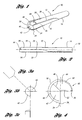
- FIG. 1 is a pictorial view of a short-hole drill bit made in accordance with the present invention;
- FIG. 2 is a side view of the short-hole drill bit shown in FIG. 1;
- FIGS. 3(a) - (c) depict the tip of the short-hole drill bit shown in FIG. 2;
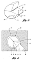
- FIG. 4 is an enlarged view of the tip of the short-hole drill bit of FIG. 2;
- FIG. 5 is a schematic diagram illustrating cutting forces associated with short-hole drill bits of the present invention;
- FIG. 6 is a schematic diagram illustrating the operation of a short-hole drill bit of the present invention for drilling a bore intersecting a blind bore;
- FIG. 7 is a side view of an alternative embodiment for a short-hole drill bit of the present invention;
- FIGS. 8 (a) - (c) illustrate the tip of the short-hole drill bit shown in FIG. 7;
- FIG. 9 is a enlarged view of the tip of the short-hole drill bit shown in FIG. 7; and
- FIG. 10 is a block diagram illustrating a method of the present invention for drilling a short-hole.
- With reference to FIGS. 1 - 4, a short-hole drill bit of the present invention is generally indicated at 10.
Drill bit 10 has aunitary body 12 with ashank portion 14, a workingportion 16, and acentral axis 18. Unitary shank and workingportions Drill bit body 12 has aperiphery 20. A substantially V-shaped flute 22 extends axially along workingportion 16.Flute 22 defines acutting edge 24 and a passive non-cuttingedge 26 atbody periphery 20. Asupport pad 30 is located along a portion ofbody periphery 20.Support pad 30 is located with respect to cuttingedge 24 based on a resultant cutting force at cuttingedge 24 during operation.Support pad 30 is located such that the resultant cutting force is directed atsupport pad 30 to causesupport pad 30 to centerdrill bit 10 during operation. Preferably,flute 22 is a straight flute; however, alternatively a twisted flute may be used. Accordingly, if a twisted flute is used, a twisted support pad is used as well such that cross sections of the drill bit are substantially identical in that the pad is always located to receive the resultant cutting force throughout the length of the cutting edge. - Further,
unitary body 12 is preferably formed of carbide, more particularly, a carbide with about 10% cobalt. Of course, other materials may be suitable for forming a sufficiently rigid drill bit. In addition to drillbit 10 being formed of a hard material, preferablybody 12 has an abrasive resistant coating. Titanium Carbon Nitride (TiCN) is one example of a suitable abrasive resistant coating, and is preferred. - As best shown in FIG. 4, in a preferred embodiment, a
short pad 34 is located along a portion ofbody periphery 20 at cuttingedge 24.Short pad 34 extends less than about 10 degrees in a circumferential direction aboutbody periphery 20. Further, it is preferred thatsupport pad 30 extends more than about 90 degrees in a circumferential direction aboutbody periphery 20. Of course, it is to be appreciated that the materials and dimensions mentioned above are examples of suitable materials and dimensions and that short-hole drill bits may be formed in accordance with the present invention having different materials and/or dimensions than those stated above. -
Body working portion 16 defines a tip, generally indicated at 40, with afirst surface 42 and asecond surface 44.First surface 42 is located adjacent to cuttingedge 24.Second surface 44 is located betweenpassive edge 26 andfirst surface 42. To facilitate centeringdrill bit 10 within a pilot hole, it is preferred thatfirst surface 42 is substantially perpendicular to bodycentral axis 18, and thatsecond surface 44 is chamfered with respect tofirst surface 42. As depicted,first surface 42 andsecond surface 44 share acommon edge 46. - Due to the importance of the ability of
drill bit 10 to center itself in a pilot hole, several features are preferred attip 40. For example,first surface 42 andsecond surface 44 oriented as described immediately above are a preferred feature attip 40. Further, the periphery oftip 40 is preferably chamfered along anouter edge 48 offirst surface 42 and along anouter edge 50 ofsecond surface 44. Further,tip 40 is preferably chamfered at anedge 52 ofsecond surface 44 that is adjacent topassive edge 26. - Referring to FIG. 5,
drill bit 10 andsupport pad 30 are shown with the cutting forces. A normal cutting force at cuttingedge 24 whendrill bit 10 is in operation is indicated at 60. A tangential cutting force at cuttingedge 24 during operation ofdrill bit 10 is indicated at 62. The resultant ofnormal cutting force 60 andtangential cutting force 62 is indicated at aresultant cutting force 64.Normal cutting force 60 is due to the interior walls of the bore hole pushing in, normally, ondrill bit 10. Tangential cuttingforce 62 is a force exerted by the interior of the bore hole against the cutting action of cuttingedge 24.Resultant force 64 is directed atsupport pad 30 in accordance with the present invention. - With reference to FIG. 6, a
drill bit 66 of the present invention is shown in operation. At a first instance, the cutting edge is indicated in solid line at 70, and the support pad is indicated in solid line at 72. At a second instance, the cutting edge is indicated in long dashed line at 74, and the support pad is indicated in long dashed line at 76. At a third instance, the cutting edge is indicated in short dashed line at 78, while the support pad is indicated in short dashed line at 80. As the cutting edge progresses along the interior wall of the bore hole it approachesblind bore 68.Support pad drill bit 66 from bending excessively. Thus, when the cutting edge moves acrossblind bore 68, becausedrill bit 66 is straight and not bent, the cutting edge smoothly leaves the area of blind bore 68 without gauging theintersection 82 of blind bore 68 with thebore hole 84 that is being drilled. - With reference to FIGS. 7 - 9, an alterative embodiment of a drill bit of the present invention is generally indicated at 90.
Drill bit 90 has aunitary body 92 with ashank portion 94 and a workingportion 96.Drill bit 90 is similar to drill bit 10 (FIGS. 1 - 4); however,drill bit 90 is shown having a twistedflute 98. Further,drill bit 90 is shown having apassage 100 extending axially throughbody 92 for routing coolant during operation. - It is to be appreciated that in preferred embodiments of the present invention the support pad extends through a portion of the drill bit body periphery that is substantially opposite the flute such that a resultant cutting force at the cutting edge is directed at the support pad. However, the positioning of the support pad, and the circumferential distance that the support pad extends may vary based on expected normal and tangential cutting forces for a given application for the drill bit.
- With reference to FIG. 10, a block diagram depicts a method for short-hole drilling a workpiece in accordance with the present invention, and is generally indicated at 110. At
block 112, a pilot hole is formed in the workpiece. Atblock 114, a short-hole drill bit is positioned at the pilot hole. The short-hole drill bit has a unitary body with a shank portion and a working portion, and has a support pad arranged such that a resultant cutting force is directed to the support pad to center the short-hole drill bit during operation. - At
blocks - Further, it is to be appreciated that the terms "short-hole drill bit" and "clean bore reamer" are used interchangeably to describe embodiments of the present invention, and that either of those terms or other similar terms are meant to encompass short-hole drill bits that are used for drilling and short-hole drill bits that are used for reaming. Still further, a suitable length to diameter ratio for a short-hole drill bit of the present invention is at most about 6 to 1. Of course, although length to diameter ratios of 6 to 1 or below are most suited for applications requiring short-hole drill bits of the present invention, length to diameter ratios greater than about 6 to 1 are possible. It is to be further appreciated that the suitable length to diameter ratios for short-hole drill bits of the present invention are far different than suitable length to diameter ratios for gun drills. In a gun drill, the length to diameter ratio may approach as much as 50 to 1. Thus, gun drills are far different than short-hole drill bits, and are used for different applications which typically include drilling but do not include reaming.
- During testing, embodiments of the present invention produced excellent results when employed in reaming applications. It is believed that embodiments of the present invention are capable of reaming a hole such that roundness, straightness, and taper are all within 2 microns. Further, embodiments of the present invention have been found to be capable of reaming bores with such precision that size will repeat within about 2 microns. From tool to tool, size will repeat within about 5 microns. Of course, it is to be appreciated that a precision spindle and tool holder should be used when an application has strict tolerances. Of course, it is to be further appreciated that the capabilities of embodiments of the present invention described in this paragraph are exemplary, and have been found by testing. Short-hole drill bits of the present invention may be configured to perform to stricter specifications or looser specifications than those described immediately above, as required for a particular application, and as would be readily understood by one of ordinary skill in the tool designing arts.
- It is to be appreciated that another advantage that may be achieved by embodiments of the present invention is that a flat bottom can be produced without a center relief, and without compromise to hole geometry. That is, in a preferred construction of a short-hole drill bit of the present invention, the cutting edge extends all the way to the tool tip to produce the flat bottom when cutting.
- In one application, embodiments of the present invention allowed the inventor to go from leaving 150 microns of stock to hone, to leaving only about 75 microns of stock to hone after reaming. Thus, by employing embodiments of the present invention, the finish honing process became easier and less expensive to perform. In another application, the inventor was able to eliminate a costly honing operation because the short-hole drill bit of the present invention was able to meet tolerances for the part. Of course, the two application described in this paragraph are exemplary only, and the performance of a short-hole drill bit may vary based on a variety of factors that would be apparent to one of ordinary skill in the tool designing arts.
- While the best mode for carrying out the invention has been described in detail, those familiar with the art to which this invention relates will recognize various alternative designs and embodiments for practicing the invention as defined by the following claims.
Claims (17)
- A short-hole drill bit (10, 90) comprising:a unitary body (12) having a shank portion (14) and a working portion (16), the body (12) defining a central axis (18) and having a periphery (20); anda substantially V-shaped flute (22) extending axially along the working portion (16), the flute (22) defining a cutting edge (24) and a passive edge (26) at the body periphery (20); and characterised bya support pad (30) located along a portion of the body periphery (20), the support pad (30) being located with respect to the cutting edge (24) based on a normal cutting force and a tangential cutting force at the cutting edge (24), such that a resultant cutting force is directed at the support pad (30) to cause the support pad (30) to centre the short-hole drill bit (10) during operation.
- The short-hole drill bit of claim 1 wherein the support pad extends through a portion of the body periphery that is substantially opposite the flute (22).
- The short-hole drill bit of claim 1 or claim 2 wherein the support pad (30) extends more than about 90 degrees in a circumferential direction about the body periphery (20).
- The short-hole drill bit of claim 1 or claim 2 further comprising:a short pad (34) located along a portion of the body periphery (20) at the cutting edge (24).
- The short-hole drill bit of claim 4 wherein the short pad (34) extends less than about 10 degrees in a circumferential direction about the body periphery (20).
- The short-hole drill bit of claim 1 or claim 2 wherein the body working portion (16) defines a tip (40) with a first surface (42) and a second surface (44), the first surface (44) being located adjacent to the cutting edge (24), the second surface being located between the passive edge (26) and the first surface (42), wherein the first surface (42) is substantially perpendicular to the body central axis (18), and the second surface (44) is chamfered with respect to the first surface (42) and shares a common edge (46) with the first surface (42).
- The short-hole drill bit of claim 6 wherein a periphery of the tip (40) is chamfered along an outer edge (48) of the first surface and along an outer edge (50) of the second surface (44).
- The short-hole drill of claim 7 wherein the tip (40) is chamfered at an edge (52) of the second surface (44) that is adjacent to the passive edge (26).
- The short-hole drill of claim 1 or claim 2 wherein the cutting edge (24) and the passive edge (26) define an interior angle of about 90 degrees.
- The short-hole drill bit (90) of claim 1 or claim 2 further comprising a passage (100) extending axially through the body (12) for routing coolant during operation.
- The short-hole drill bit of claim 1 or claim 2 wherein the flute (22) is a straight flute.
- The short-hole drill bit of claim 1 or claim 2 wherein the body (12) is formed of a carbide.
- The short-hole drill bit of claim 12 wherein the body (12) is formed of a carbide with about 10 percent Cobalt.
- The short-hole drill bit of claim 1 or claim 2 wherein the body (12) has an abrasive resistant coating.
- The short-hole drill bit of claim 14 wherein the body has a TiCN coating.
- The short-hole drill of claim 1 or claim 2 wherein the body (12) is formed from a single piece of metal, the body (12) having an axial length of not significantly less than a desired depth for a drilled hole.
- A method for short-hole drilling a workpiece, the method comprising:forming a pilot hole in the workpiece;positioning a short-hole drill bit at the pilot hole; andforming the short-hole in the workpiece,wherein the short-hole drill bit (10, 90) having a unitary body (12) having a shank portion (14) and a working portion (16), the body defining a central axis (18) and having a periphery (20) with a substantially V-shaped flute (22) extending axially along the working portion (16), the flute (22) defining a cutting edge (24) and a passive edge (26) at the body periphery (20)
and characterised by
a support pad (30)located along a portion of the body periphery (20), the support pad (30) being located with respect to the cutting edge (24) based on a normal cutting force and a tangential cutting force at the cutting edge, such that a resultant cutting force is directed at the support pad (30) to cause the support pad to center the short-hole drill bit during operation;
wherein the support pad (30) centres the short-hole drill bit during drilling.
Applications Claiming Priority (3)
| Application Number | Priority Date | Filing Date | Title |
|---|---|---|---|
| US09/124,482 US5967707A (en) | 1998-07-29 | 1998-07-29 | Short-hole drill bit |
| US124482 | 1998-07-29 | ||
| PCT/US1999/017006 WO2000006329A2 (en) | 1998-07-29 | 1999-07-27 | Short-hole drill bit |
Publications (3)
| Publication Number | Publication Date |
|---|---|
| EP1115524A2 EP1115524A2 (en) | 2001-07-18 |
| EP1115524A4 EP1115524A4 (en) | 2004-05-06 |
| EP1115524B1 true EP1115524B1 (en) | 2007-05-30 |
Family
ID=22415150
Family Applications (1)
| Application Number | Title | Priority Date | Filing Date |
|---|---|---|---|
| EP99937540A Expired - Lifetime EP1115524B1 (en) | 1998-07-29 | 1999-07-27 | Short-hole drill bit |
Country Status (6)
| Country | Link |
|---|---|
| US (1) | US5967707A (en) |
| EP (1) | EP1115524B1 (en) |
| JP (1) | JP2002521223A (en) |
| CA (1) | CA2338810A1 (en) |
| DE (1) | DE69936218T2 (en) |
| WO (1) | WO2000006329A2 (en) |
Families Citing this family (8)
| Publication number | Priority date | Publication date | Assignee | Title |
|---|---|---|---|---|
| JP3847016B2 (en) * | 1998-12-09 | 2006-11-15 | 富士精工株式会社 | Round hole finishing method and single-blade reamer |
| AU7078800A (en) * | 1999-08-31 | 2001-03-26 | Bitmoore | Center locating feature in drill bit formed without a pointed tip |
| JP4740842B2 (en) * | 2004-03-26 | 2011-08-03 | 株式会社牧野フライス製作所 | Cutting method and apparatus |
| JP4955261B2 (en) * | 2005-12-02 | 2012-06-20 | ユニタック株式会社 | Gun drill |
| RU2497639C2 (en) * | 2009-05-29 | 2013-11-10 | Тунгалой Корпорейшн | Reamer |
| DE102010050351A1 (en) * | 2010-11-05 | 2012-05-10 | Botek Präzisionsbohrtechnik Gmbh | gun drills |
| MX2024005383A (en) * | 2021-12-13 | 2024-05-23 | Iscar Ltd | CUTTING TOOL PART HAVING ADDITIVELY MANUFACTURED CUTTING PORTION WITH INTEGRALLY FORMED GUIDE PADS AND METHOD OF MANUFACTURING SAME. |
| JP7515534B2 (en) * | 2022-05-02 | 2024-07-12 | 株式会社タンガロイ | Gun drill body |
Family Cites Families (34)
| Publication number | Priority date | Publication date | Assignee | Title |
|---|---|---|---|---|
| US1323278A (en) * | 1919-12-02 | Barrel-reamer | ||
| US26452A (en) * | 1859-12-13 | underbill | ||
| US499098A (en) * | 1893-06-06 | Pipe-burr-removing implement | ||
| FR507822A (en) * | 1919-03-12 | 1920-09-24 | Hippolyte Caillon | Edge drill cutting to the center of the hole |
| US1454851A (en) * | 1919-07-16 | 1923-05-15 | Gerdil Henri Prosper | Drill |
| US2188928A (en) * | 1936-06-20 | 1940-02-06 | Charles W Stevens | Drill for drilling holes in wood |
| US2276532A (en) * | 1940-05-29 | 1942-03-17 | Bethlehem Steel Corp | Drill |
| US2289065A (en) * | 1941-01-02 | 1942-07-07 | Edd C Oliver | Drill for rifle barrels |
| US2325535A (en) * | 1941-10-28 | 1943-07-27 | Albert J Nordberg | Drill |
| US2354985A (en) * | 1943-05-22 | 1944-08-01 | Charles H Davis | Drill |
| US3120766A (en) * | 1961-04-14 | 1964-02-11 | Zagar Inc | Gun type drilling means |
| US3147645A (en) * | 1961-11-06 | 1964-09-08 | Don T Cooper | Boring tool |
| FR1363457A (en) * | 1962-05-10 | 1964-06-12 | Stora Kopparbergs Bergslags Ab | Drill bit for deep drilling |
| US3260139A (en) * | 1963-08-07 | 1966-07-12 | Sanborn Frank Eugene | Self-clearing drill |
| USRE26452E (en) | 1964-10-20 | 1968-09-10 | Gun drill | |
| US3361014A (en) * | 1965-07-28 | 1968-01-02 | Mcclennan Morton | Gun drill guide |
| US3400617A (en) * | 1966-07-18 | 1968-09-10 | Frank E. Sanborn | Drill bit tip |
| US4212569A (en) * | 1977-10-06 | 1980-07-15 | Sandvik Aktiebolag | Tubular drill tool |
| JPS5943245B2 (en) * | 1978-10-11 | 1984-10-20 | 三菱マテリアル株式会社 | 1-blade drilling tool |
| JPS5554112A (en) * | 1978-10-11 | 1980-04-21 | Mitsubishi Metal Corp | Single-edge drill |
| JPS6110887Y2 (en) * | 1979-07-04 | 1986-04-07 | ||
| US4338050A (en) * | 1980-07-07 | 1982-07-06 | The Boeing Company | Method and tool for generating holes in composite materials |
| JPS6039408U (en) * | 1983-08-24 | 1985-03-19 | 三菱マテリアル株式会社 | Some non-grinding carbide drills |
| JPS629811A (en) * | 1985-07-08 | 1987-01-17 | Mitsubishi Metal Corp | Gun drill |
| JPS6234712A (en) * | 1985-08-06 | 1987-02-14 | Mitsubishi Metal Corp | Gun drill |
| JPH0724970B2 (en) * | 1986-03-11 | 1995-03-22 | 三菱マテリアル株式会社 | Gun drill |
| JPS63102813A (en) * | 1986-10-21 | 1988-05-07 | Mitsubishi Metal Corp | gun drill |
| JPS63245311A (en) * | 1987-03-30 | 1988-10-12 | Mitsubishi Metal Corp | Drill |
| JPS63278711A (en) * | 1987-05-09 | 1988-11-16 | Mitsubishi Metal Corp | Brazed reamer |
| JPS6451216A (en) * | 1987-08-18 | 1989-02-27 | Mitsubishi Metal Corp | Gun drill |
| JP2555676B2 (en) * | 1988-03-22 | 1996-11-20 | 三菱マテリアル株式会社 | Surface coated tungsten carbide based cemented carbide end mills and drills |
| JP2890592B2 (en) * | 1989-01-26 | 1999-05-17 | 住友電気工業株式会社 | Carbide alloy drill |
| JP2984446B2 (en) * | 1992-01-07 | 1999-11-29 | 三菱重工業株式会社 | Drill |
| JP3515158B2 (en) * | 1994-02-25 | 2004-04-05 | 三菱マテリアル株式会社 | Gun drill |
-
1998
- 1998-07-29 US US09/124,482 patent/US5967707A/en not_active Expired - Lifetime
-
1999
- 1999-07-27 DE DE69936218T patent/DE69936218T2/en not_active Expired - Lifetime
- 1999-07-27 CA CA002338810A patent/CA2338810A1/en not_active Abandoned
- 1999-07-27 JP JP2000562168A patent/JP2002521223A/en active Pending
- 1999-07-27 WO PCT/US1999/017006 patent/WO2000006329A2/en not_active Ceased
- 1999-07-27 EP EP99937540A patent/EP1115524B1/en not_active Expired - Lifetime
Also Published As
| Publication number | Publication date |
|---|---|
| DE69936218D1 (en) | 2007-07-12 |
| EP1115524A4 (en) | 2004-05-06 |
| WO2000006329A2 (en) | 2000-02-10 |
| DE69936218T2 (en) | 2008-02-28 |
| WO2000006329A3 (en) | 2000-05-04 |
| JP2002521223A (en) | 2002-07-16 |
| CA2338810A1 (en) | 2000-02-10 |
| US5967707A (en) | 1999-10-19 |
| EP1115524A2 (en) | 2001-07-18 |
Similar Documents
| Publication | Publication Date | Title |
|---|---|---|
| CA2295224C (en) | Twist drill for dry boring | |
| US4936721A (en) | Drill reamer bit | |
| US9844819B2 (en) | Twist drill for metal machining | |
| US4620822A (en) | Flat bottom hole drill | |
| KR20040039373A (en) | Cutting point for a drill | |
| US7722299B2 (en) | Twist drill | |
| WO2012111004A2 (en) | Rotary cutter | |
| WO2012021211A2 (en) | Cutting tool with unequal flute spacing | |
| US7278806B1 (en) | Two edge deburring tool | |
| CN102294569A (en) | Processing technic of small-diameter thin-wall deep-hole high-accuracy part and special grinding tool applied to same | |
| WO2004069456A1 (en) | Drill for making a flat-bottomed hole | |
| KR20020017908A (en) | Drilling tool | |
| EP0088037A1 (en) | Single pass drill | |
| US5967707A (en) | Short-hole drill bit | |
| JPH02303704A (en) | Burnishing drill reamer for high speed and feeding | |
| US11571754B2 (en) | Single-lip deep-hole drill with a chamfered rake face | |
| JP4941356B2 (en) | Drilling tool | |
| KR20010021469A (en) | Cutting tool and throwaway center drill | |
| US6206619B1 (en) | Non-adjustable single cylindrical lip boring tool | |
| EP4410461B1 (en) | Drill and method of producing drilled product | |
| EP3932599B1 (en) | A metal cutting indexable drill tool | |
| KR102686399B1 (en) | Burnishing drill having joining structure of guide pad tip | |
| CN218657124U (en) | Strong chip-removing straight-groove reamer | |
| KR200211512Y1 (en) | Reamer for complex machining | |
| KR100427339B1 (en) | Reamer for complex working |
Legal Events
| Date | Code | Title | Description |
|---|---|---|---|
| PUAI | Public reference made under article 153(3) epc to a published international application that has entered the european phase |
Free format text: ORIGINAL CODE: 0009012 |
|
| 17P | Request for examination filed |
Effective date: 20010203 |
|
| AK | Designated contracting states |
Kind code of ref document: A2 Designated state(s): AT BE CH CY DE DK ES FI FR GB GR IE IT LI LU MC NL PT SE |
|
| A4 | Supplementary search report drawn up and despatched |
Effective date: 20040323 |
|
| RIC1 | Information provided on ipc code assigned before grant |
Ipc: 7B 23B 51/02 B Ipc: 7B 23B 1/00 A |
|
| 17Q | First examination report despatched |
Effective date: 20041216 |
|
| GRAP | Despatch of communication of intention to grant a patent |
Free format text: ORIGINAL CODE: EPIDOSNIGR1 |
|
| RBV | Designated contracting states (corrected) |
Designated state(s): DE FR GB |
|
| GRAC | Information related to communication of intention to grant a patent modified |
Free format text: ORIGINAL CODE: EPIDOSCIGR1 |
|
| GRAS | Grant fee paid |
Free format text: ORIGINAL CODE: EPIDOSNIGR3 |
|
| GRAA | (expected) grant |
Free format text: ORIGINAL CODE: 0009210 |
|
| AK | Designated contracting states |
Kind code of ref document: B1 Designated state(s): DE FR GB |
|
| REG | Reference to a national code |
Ref country code: GB Ref legal event code: FG4D |
|
| REF | Corresponds to: |
Ref document number: 69936218 Country of ref document: DE Date of ref document: 20070712 Kind code of ref document: P |
|
| ET | Fr: translation filed | ||
| PLBE | No opposition filed within time limit |
Free format text: ORIGINAL CODE: 0009261 |
|
| STAA | Information on the status of an ep patent application or granted ep patent |
Free format text: STATUS: NO OPPOSITION FILED WITHIN TIME LIMIT |
|
| 26N | No opposition filed |
Effective date: 20080303 |
|
| PGFP | Annual fee paid to national office [announced via postgrant information from national office to epo] |
Ref country code: FR Payment date: 20130719 Year of fee payment: 15 Ref country code: GB Payment date: 20130723 Year of fee payment: 15 |
|
| PGFP | Annual fee paid to national office [announced via postgrant information from national office to epo] |
Ref country code: DE Payment date: 20130926 Year of fee payment: 15 |
|
| REG | Reference to a national code |
Ref country code: DE Ref legal event code: R119 Ref document number: 69936218 Country of ref document: DE |
|
| GBPC | Gb: european patent ceased through non-payment of renewal fee |
Effective date: 20140727 |
|
| REG | Reference to a national code |
Ref country code: FR Ref legal event code: ST Effective date: 20150331 |
|
| PG25 | Lapsed in a contracting state [announced via postgrant information from national office to epo] |
Ref country code: DE Free format text: LAPSE BECAUSE OF NON-PAYMENT OF DUE FEES Effective date: 20150203 |
|
| REG | Reference to a national code |
Ref country code: DE Ref legal event code: R119 Ref document number: 69936218 Country of ref document: DE Effective date: 20150203 |
|
| PG25 | Lapsed in a contracting state [announced via postgrant information from national office to epo] |
Ref country code: FR Free format text: LAPSE BECAUSE OF NON-PAYMENT OF DUE FEES Effective date: 20140731 Ref country code: GB Free format text: LAPSE BECAUSE OF NON-PAYMENT OF DUE FEES Effective date: 20140727 |