EP1115191A2 - Connection assembly particularly for the windings of a stator of an electric motor - Google Patents
Connection assembly particularly for the windings of a stator of an electric motor Download PDFInfo
- Publication number
- EP1115191A2 EP1115191A2 EP00128111A EP00128111A EP1115191A2 EP 1115191 A2 EP1115191 A2 EP 1115191A2 EP 00128111 A EP00128111 A EP 00128111A EP 00128111 A EP00128111 A EP 00128111A EP 1115191 A2 EP1115191 A2 EP 1115191A2
- Authority
- EP
- European Patent Office
- Prior art keywords
- connection assembly
- assembly according
- connection
- shaped
- stator
- Prior art date
- Legal status (The legal status is an assumption and is not a legal conclusion. Google has not performed a legal analysis and makes no representation as to the accuracy of the status listed.)
- Granted
Links
Images

Classifications
-
- H—ELECTRICITY
- H02—GENERATION; CONVERSION OR DISTRIBUTION OF ELECTRIC POWER
- H02K—DYNAMO-ELECTRIC MACHINES
- H02K5/00—Casings; Enclosures; Supports
- H02K5/04—Casings or enclosures characterised by the shape, form or construction thereof
- H02K5/22—Auxiliary parts of casings not covered by groups H02K5/06-H02K5/20, e.g. shaped to form connection boxes or terminal boxes
- H02K5/225—Terminal boxes or connection arrangements
-
- H—ELECTRICITY
- H01—ELECTRIC ELEMENTS
- H01R—ELECTRICALLY-CONDUCTIVE CONNECTIONS; STRUCTURAL ASSOCIATIONS OF A PLURALITY OF MUTUALLY-INSULATED ELECTRICAL CONNECTING ELEMENTS; COUPLING DEVICES; CURRENT COLLECTORS
- H01R39/00—Rotary current collectors, distributors or interrupters
- H01R39/02—Details for dynamo electric machines
- H01R39/32—Connections of conductor to commutator segment
-
- H—ELECTRICITY
- H02—GENERATION; CONVERSION OR DISTRIBUTION OF ELECTRIC POWER
- H02K—DYNAMO-ELECTRIC MACHINES
- H02K3/00—Details of windings
- H02K3/46—Fastening of windings on the stator or rotor structure
- H02K3/52—Fastening salient pole windings or connections thereto
- H02K3/521—Fastening salient pole windings or connections thereto applicable to stators only
- H02K3/522—Fastening salient pole windings or connections thereto applicable to stators only for generally annular cores with salient poles
-
- H—ELECTRICITY
- H01—ELECTRIC ELEMENTS
- H01R—ELECTRICALLY-CONDUCTIVE CONNECTIONS; STRUCTURAL ASSOCIATIONS OF A PLURALITY OF MUTUALLY-INSULATED ELECTRICAL CONNECTING ELEMENTS; COUPLING DEVICES; CURRENT COLLECTORS
- H01R13/00—Details of coupling devices of the kinds covered by groups H01R12/70 or H01R24/00 - H01R33/00
- H01R13/02—Contact members
- H01R13/10—Sockets for co-operation with pins or blades
- H01R13/11—Resilient sockets
- H01R13/115—U-shaped sockets having inwardly bent legs, e.g. spade type
-
- H—ELECTRICITY
- H01—ELECTRIC ELEMENTS
- H01R—ELECTRICALLY-CONDUCTIVE CONNECTIONS; STRUCTURAL ASSOCIATIONS OF A PLURALITY OF MUTUALLY-INSULATED ELECTRICAL CONNECTING ELEMENTS; COUPLING DEVICES; CURRENT COLLECTORS
- H01R4/00—Electrically-conductive connections between two or more conductive members in direct contact, i.e. touching one another; Means for effecting or maintaining such contact; Electrically-conductive connections having two or more spaced connecting locations for conductors and using contact members penetrating insulation
- H01R4/10—Electrically-conductive connections between two or more conductive members in direct contact, i.e. touching one another; Means for effecting or maintaining such contact; Electrically-conductive connections having two or more spaced connecting locations for conductors and using contact members penetrating insulation effected solely by twisting, wrapping, bending, crimping, or other permanent deformation
- H01R4/18—Electrically-conductive connections between two or more conductive members in direct contact, i.e. touching one another; Means for effecting or maintaining such contact; Electrically-conductive connections having two or more spaced connecting locations for conductors and using contact members penetrating insulation effected solely by twisting, wrapping, bending, crimping, or other permanent deformation by crimping
- H01R4/183—Electrically-conductive connections between two or more conductive members in direct contact, i.e. touching one another; Means for effecting or maintaining such contact; Electrically-conductive connections having two or more spaced connecting locations for conductors and using contact members penetrating insulation effected solely by twisting, wrapping, bending, crimping, or other permanent deformation by crimping for cylindrical elongated bodies, e.g. cables having circular cross-section
- H01R4/184—Electrically-conductive connections between two or more conductive members in direct contact, i.e. touching one another; Means for effecting or maintaining such contact; Electrically-conductive connections having two or more spaced connecting locations for conductors and using contact members penetrating insulation effected solely by twisting, wrapping, bending, crimping, or other permanent deformation by crimping for cylindrical elongated bodies, e.g. cables having circular cross-section comprising a U-shaped wire-receiving portion
- H01R4/185—Electrically-conductive connections between two or more conductive members in direct contact, i.e. touching one another; Means for effecting or maintaining such contact; Electrically-conductive connections having two or more spaced connecting locations for conductors and using contact members penetrating insulation effected solely by twisting, wrapping, bending, crimping, or other permanent deformation by crimping for cylindrical elongated bodies, e.g. cables having circular cross-section comprising a U-shaped wire-receiving portion combined with a U-shaped insulation-receiving portion
-
- H—ELECTRICITY
- H01—ELECTRIC ELEMENTS
- H01R—ELECTRICALLY-CONDUCTIVE CONNECTIONS; STRUCTURAL ASSOCIATIONS OF A PLURALITY OF MUTUALLY-INSULATED ELECTRICAL CONNECTING ELEMENTS; COUPLING DEVICES; CURRENT COLLECTORS
- H01R4/00—Electrically-conductive connections between two or more conductive members in direct contact, i.e. touching one another; Means for effecting or maintaining such contact; Electrically-conductive connections having two or more spaced connecting locations for conductors and using contact members penetrating insulation
- H01R4/24—Connections using contact members penetrating or cutting insulation or cable strands
- H01R4/2416—Connections using contact members penetrating or cutting insulation or cable strands the contact members having insulation-cutting edges, e.g. of tuning fork type
- H01R4/242—Connections using contact members penetrating or cutting insulation or cable strands the contact members having insulation-cutting edges, e.g. of tuning fork type the contact members being plates having a single slot
Definitions
- the present invention relates to a connection assembly particularly for the windings of a stator of an electric motor.
- connection in fact entails connecting one or a plurality of wires which exit from the stator and must be connected to a matching number of wires that arrive from the power supply.
- connection terminals which are anchored in various manners, usually to the stator pack.
- the aim of the present invention is to provide a connection assembly, particularly for the seats of a stator of an electric motor, which solves the drawbacks noted above in conventional connectors or connection assemblies, particularly ensuring an effective and safe connection of the power supply wires or cables to the stator wires.
- an object of the present invention is to provide a connection assembly which allows a substantially automatic or semiautomatic assembly and ensures, during application, an equally safe and easy application of the connections on the part of the operator.
- Another object of the present invention is to provide high flexibility in application both in relation to the type of motor on which the assembly is applied and in relation to the intended use of the motor.
- Another object of the present invention is to provide a connection assembly which can be mass-manufactured and which can be assembled in an automated or partly automated manner.
- Another object of the present invention is to provide a connection assembly which can be manufactured at competitive costs with respect to assemblies or connectors having similar functionality.
- connection assembly particularly for the windings of a stator of an electric motor, characterized in that it comprises a connector which is constituted by a first section for connection to terminals of the stator winding and a second section for anchoring to the stator of the electric motor, said first section accommodating one or a plurality of female terminals which are adapted for connection to one or a plurality of complementary male terminals which are connected to the stator windings and to the thermal protection device, said first section being constituted by a box-like body which is shaped so as to form one or a plurality of seats which are electrically insulated from each other, each seat being designed to accommodate a corresponding female terminal which is shaped substantially complementarily, the walls that form each one of said seats forming, for said seats, a substantially L-shaped extension with a connecting portion which on assembly is aligned with the longitudinal extension of said male terminals and is provided with an opening for the insertion of at least part of a corresponding one
- connection assembly particularly for the windings of a stator of an electric motor, according to the invention, is generally designated by the reference numeral 10.
- the assembly 10 is applied to the stator 11 of an electric motor, which is generally designated by the reference numeral 12 and is shown only partially in the figures.
- the assembly 10 comprises a connector 13 which is constituted by a first section 14 for connection to the terminals, which are described in greater detail hereinafter, and a second section 15 for anchoring to the stator 11 of the motor 12.
- the first section 14 accommodates one or a plurality of female terminals, designated by the reference numeral 16, which are connected to one or a plurality of complementary male terminals 17 which are connected to the stator windings.
- the first section 14 is constituted by a box-like body 18 which is shaped so as to form one or a plurality of seats 19 which are electrically insulated; each seat is designed to accommodate a corresponding female terminal 16 which is shaped substantially complementarily.
- each one of the seats 19 form, for said seats, a substantially L-shaped extension, with a first connecting portion 20 which on assembly is aligned with the longitudinal extension of the male terminals 17 and is provided with a first opening 21 for the insertion of at least part of a corresponding one of the male terminals, and a second portion 22 which lies substantially at right angles to the first portion 20, is designed to support a corresponding female terminal 16 and is provided with a second end opening 23 for the insertion of the corresponding end portion of the corresponding power supply cable, designated by the reference numeral 24 in the figures.
- the body 18 has, for each one of the first portions 20, at the internal definition surface that lies opposite the second portion 22, a second retention tab 25 which is laminar and elastically flexible and is inclined with respect to the plane of arrangement of the elevation wall, which has a free end 26 which is raised with respect to the latter so as to form a locking abutment surface for part of the corresponding female terminal 16 in the opposite direction with respect to the insertion direction.
- the body 18 is shaped, for each one of the first portions 20 at the definition surface that lies opposite the one related to the first tab 25, so as to form a straight channel 27 for guiding the insertion of the corresponding female terminal 16.
- the first opening 21 is shaped substantially complementarily to the insertion portion of the corresponding male terminal 17 and is arranged so as to guide the latter in insertion in the corresponding female terminal portion 16 which is described in detail hereinafter.
- the body 18 is shaped, at one of said second openings 23, so as to form a recess 28 which is associated with retention means, described hereinafter, for accommodating in a predefined position the end portion of a corresponding power supply cable 24.
- the retention means are constituted by opposite teeth 29; however, in other cases, the operator may, in view of the particular situation of application, not use teeth 29, allowing the corresponding cable 24 to exit in a straight line, as shown in dashed lines in Figure 2.
- Each one of the recesses 28 is surrounded by a guiding border 30 which lies substantially parallel to the corresponding and opposite first portion 20.
- the second section 15 is constituted by a second hollow tab 31, with a transverse cross-section which is shaped complementarily to the insertion seat formed in the stator 11 and with a longitudinal extension which is substantially parallel to the first portion 20; the second tab 31 constitutes the seat for the thermal protection device, which is of a per se known type not shown in the figures.
- the second tab 31 is monolithic with respect to the free end of a bracket 32 which is in turn monolithic with respect to the body 18 in a position which lies opposite the position for the insertion of the power supply cables 24.
- the second tab 31, thanks to its shape and position, also allows to accommodate the thermal protection device even after connection has occurred.
- the connector 13 also has a cover 33 with an opening and closure path of the edge-hinged type which is transverse to the path for the insertion of the power supply cables 24.
- the cover 33 is fixed and pivoted laterally to the body 18 by means of bands 34 which are monolithic thereto and are provided with a weaker region for folding.
- the cover 33 is also associated with locking means which are constituted, in this case, by monolithic teeth 35 which cantilever out from the body 18, are arranged opposite the pivoting bands 34 and are adapted to enter corresponding holes 36 (shown in dashed lines in Figure 7) which are formed at the free end of the cover 33.
- the cover is also provided with internal reinforcement ridges 37.
- each one of the female terminals 16 comprises a laminar body 38 which is substantially L-shaped and complementary to the corresponding seat 19 and has a third connection portion 39, which comprises a pair of first opposite wings 40 with free ends 41 which are folded toward the body 38 so as to form the insertion seat of the corresponding male terminal portion 17, and a fourth portion 42, which is provided with two pairs, respectively, of second wings 43 and third wings 44 for clinching to the stripped end region of the corresponding power supply cable 24.
- the body 38 of the female terminal 16 is shaped in opposition to the first wings 40 so as to form a linear stud 45 for guiding the insertion in the corresponding channel 27 formed in the corresponding first portion 20 of the seat 19.
- the first wings 40 are shaped so as to form folds with a circular arc-like profile which delimit an insertion section which is such as to force the corresponding male terminal 17 to perform insertion with elastic forcing.
- the second wings 43 are longer than the third wings 44.
- Each one of the male terminals 17 is constituted by a laminar body 47 which has a fifth portion 48 which is shaped so as to form a laminar tang 49 for insertion upon connection in the section formed by said first wings 40, which is radiused and monolithic with respect to a sixth portion 50 which has an end 51 for connection to the wires of the stator windings, designated by the reference numeral 52.
- the fifth portion 48 has a free end 53 which tapers outwards in order to guide insertion.
- the end 51 is provided with fifth opposite wings 54 which are folded on the plane of arrangement of the body 47 of said male terminal 17 with free ends 55 which converge at the axis of said end 51, so as to form a self-centering tapering seat 56 for a corresponding wire of the stator 11.
- the fifth wings 54 are shaped at facing edge portions 57 so as to form blades 58 which are adapted to punch through the insulating sheath of the accommodated wire.
- the end 51 has, in this case also, two pairs of third tabs 59 for retention in elevation with the free end with respect to the arrangement of the end 51.
- end 51 is laterally provided with two retention teeth 60.
- the laminar body 47 is shaped so as to form substantially two parallel ends 51 which are arranged symmetrically opposite with respect to the axis of the fifth portion 48.
- the second section 15 also comprises an auxiliary element for connection to the stator 11, which is associated with the body 18; the auxiliary element is shaped like a half box and so as to form parallel seats which are adapted for the guided connection of the end portions of the stator windings to corresponding ends 51 of the male terminals 17 inserted therein.
- the assembly 10 can be advantageously preassembled separately from the stator 11.
- connection assembly according to the invention, which allows, both during production of the electric motor and during connection thereof to the power supply, connections which are safe in terms of short-circuits or damage to the components and for the operator.
- connection assembly allows high automation both in the manufacture of the electric motor and in the manufacture of said assembly, also allowing last-minute modifications in the arrangement and setting of the connections.
- connection assembly according to the invention by virtue of its structure, allows mass-production with costs and times which are competitive with respect to connectors having similar functionalities.
- the materials and the dimensions may be any according to requirements.
Landscapes
- Engineering & Computer Science (AREA)
- Power Engineering (AREA)
- Insulation, Fastening Of Motor, Generator Windings (AREA)
- Motor Or Generator Frames (AREA)
- Manufacture Of Motors, Generators (AREA)
Abstract
Description
- The present invention relates to a connection assembly particularly for the windings of a stator of an electric motor.
- It is known that electric motor manufacturers have long been tending increasingly toward automation in the manufacture of said motors, particularly by designing components which can be easily assembled automatically or at least semiautomatically.
- One of the critical steps in the manufacturing process of electric motors is the connection of the stator windings to the power supply.
- This connection in fact entails connecting one or a plurality of wires which exit from the stator and must be connected to a matching number of wires that arrive from the power supply.
- This connection must be safe in terms of layout and free from unwanted contacts and short-circuits, and must give assurance to operators, both during assembly and during manufacture, that application occurs easily and safely as regards possible injury.
- For this purpose, a very large number of connectors or connection assemblies have been designed and are currently commercially available which substantially provide predefined seats for the connection terminals, which are anchored in various manners, usually to the stator pack.
- The development of such connectors or connection assemblies, however, has not yet reached its optimum level, since there are still considerable problems in harmonizing them with an automatic or at least semiautomatic manufacturing process.
- Moreover, good flexibility in application in relation to the type of motor to which they are applied is sometimes not available.
- The aim of the present invention is to provide a connection assembly, particularly for the seats of a stator of an electric motor, which solves the drawbacks noted above in conventional connectors or connection assemblies, particularly ensuring an effective and safe connection of the power supply wires or cables to the stator wires.
- Within this aim, an object of the present invention is to provide a connection assembly which allows a substantially automatic or semiautomatic assembly and ensures, during application, an equally safe and easy application of the connections on the part of the operator.
- Another object of the present invention is to provide high flexibility in application both in relation to the type of motor on which the assembly is applied and in relation to the intended use of the motor.
- Another object of the present invention is to provide a connection assembly which can be mass-manufactured and which can be assembled in an automated or partly automated manner.
- Another object of the present invention is to provide a connection assembly which can be manufactured at competitive costs with respect to assemblies or connectors having similar functionality.
- These and other objects which will become better apparent hereinafter are achieved by a connection assembly, particularly for the windings of a stator of an electric motor, characterized in that it comprises a connector which is constituted by a first section for connection to terminals of the stator winding and a second section for anchoring to the stator of the electric motor, said first section accommodating one or a plurality of female terminals which are adapted for connection to one or a plurality of complementary male terminals which are connected to the stator windings and to the thermal protection device, said first section being constituted by a box-like body which is shaped so as to form one or a plurality of seats which are electrically insulated from each other, each seat being designed to accommodate a corresponding female terminal which is shaped substantially complementarily, the walls that form each one of said seats forming, for said seats, a substantially L-shaped extension with a connecting portion which on assembly is aligned with the longitudinal extension of said male terminals and is provided with an opening for the insertion of at least part of a corresponding one of said terminals, and a second portion which has an extension which is substantially perpendicular to said first portion for supporting a corresponding female terminal and is provided with a second end opening for the insertion of the corresponding end portion of the corresponding power supply cable.
- Further characteristics and advantages of the present invention will become better apparent from the following detailed description of some embodiments thereof, illustrated only by way of non-limitative example in the accompanying drawings, wherein:
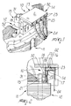
- Figure 1 is a perspective view of a connection assembly according to the invention, applied to the stator of an electric motor;
- Figure 2 is a partially sectional view of the assembly of Figure 1;
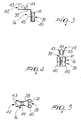
- Figures 3 to 5 are various views of a same component of the assembly of Figure 1;
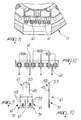
- Figure 6 is a partially sectional view of the assembly of Figure 1;
- Figure 7 is a view of the assembly of Figure 1;
- Figure 8 is a partially sectional view of another component of the assembly of Figure 1;
- Figures 9 and 10 are various views of another embodiment of the component of the assembly of Figure 1;
- Figure 11 is a partially sectional view of another component of the assembly of Figure 1, applied to the stator;
- Figure 12 is another partially sectional view of the component of Figure 11.
-
- With reference to Figures 1 to 12, a connection assembly particularly for the windings of a stator of an electric motor, according to the invention, is generally designated by the
reference numeral 10. - In particular, in this case the
assembly 10 is applied to thestator 11 of an electric motor, which is generally designated by thereference numeral 12 and is shown only partially in the figures. - The
assembly 10 comprises aconnector 13 which is constituted by afirst section 14 for connection to the terminals, which are described in greater detail hereinafter, and asecond section 15 for anchoring to thestator 11 of themotor 12. - The
first section 14 accommodates one or a plurality of female terminals, designated by thereference numeral 16, which are connected to one or a plurality of complementarymale terminals 17 which are connected to the stator windings. - Moreover, the
first section 14 is constituted by a box-like body 18 which is shaped so as to form one or a plurality ofseats 19 which are electrically insulated; each seat is designed to accommodate a correspondingfemale terminal 16 which is shaped substantially complementarily. - The walls that constitute each one of the
seats 19 form, for said seats, a substantially L-shaped extension, with a first connectingportion 20 which on assembly is aligned with the longitudinal extension of themale terminals 17 and is provided with afirst opening 21 for the insertion of at least part of a corresponding one of the male terminals, and asecond portion 22 which lies substantially at right angles to thefirst portion 20, is designed to support a correspondingfemale terminal 16 and is provided with a second end opening 23 for the insertion of the corresponding end portion of the corresponding power supply cable, designated by thereference numeral 24 in the figures. - The
body 18 has, for each one of thefirst portions 20, at the internal definition surface that lies opposite thesecond portion 22, a second retention tab 25 which is laminar and elastically flexible and is inclined with respect to the plane of arrangement of the elevation wall, which has afree end 26 which is raised with respect to the latter so as to form a locking abutment surface for part of the correspondingfemale terminal 16 in the opposite direction with respect to the insertion direction. - The
body 18 is shaped, for each one of thefirst portions 20 at the definition surface that lies opposite the one related to the first tab 25, so as to form astraight channel 27 for guiding the insertion of the correspondingfemale terminal 16. - The
first opening 21 is shaped substantially complementarily to the insertion portion of the correspondingmale terminal 17 and is arranged so as to guide the latter in insertion in the correspondingfemale terminal portion 16 which is described in detail hereinafter. - The
body 18 is shaped, at one of saidsecond openings 23, so as to form arecess 28 which is associated with retention means, described hereinafter, for accommodating in a predefined position the end portion of a correspondingpower supply cable 24. - In particular, the retention means are constituted by
opposite teeth 29; however, in other cases, the operator may, in view of the particular situation of application, not useteeth 29, allowing thecorresponding cable 24 to exit in a straight line, as shown in dashed lines in Figure 2. - Each one of the
recesses 28 is surrounded by a guidingborder 30 which lies substantially parallel to the corresponding and oppositefirst portion 20. - The
second section 15 is constituted by a secondhollow tab 31, with a transverse cross-section which is shaped complementarily to the insertion seat formed in thestator 11 and with a longitudinal extension which is substantially parallel to thefirst portion 20; thesecond tab 31 constitutes the seat for the thermal protection device, which is of a per se known type not shown in the figures. - The
second tab 31 is monolithic with respect to the free end of abracket 32 which is in turn monolithic with respect to thebody 18 in a position which lies opposite the position for the insertion of thepower supply cables 24. Thesecond tab 31, thanks to its shape and position, also allows to accommodate the thermal protection device even after connection has occurred. - The
connector 13 also has acover 33 with an opening and closure path of the edge-hinged type which is transverse to the path for the insertion of thepower supply cables 24. - The
cover 33 is fixed and pivoted laterally to thebody 18 by means ofbands 34 which are monolithic thereto and are provided with a weaker region for folding. - The
cover 33 is also associated with locking means which are constituted, in this case, bymonolithic teeth 35 which cantilever out from thebody 18, are arranged opposite thepivoting bands 34 and are adapted to enter corresponding holes 36 (shown in dashed lines in Figure 7) which are formed at the free end of thecover 33. - The cover is also provided with
internal reinforcement ridges 37. - In this case, each one of the
female terminals 16 comprises alaminar body 38 which is substantially L-shaped and complementary to thecorresponding seat 19 and has athird connection portion 39, which comprises a pair of firstopposite wings 40 withfree ends 41 which are folded toward thebody 38 so as to form the insertion seat of the correspondingmale terminal portion 17, and afourth portion 42, which is provided with two pairs, respectively, ofsecond wings 43 andthird wings 44 for clinching to the stripped end region of the correspondingpower supply cable 24. - The
body 38 of thefemale terminal 16 is shaped in opposition to thefirst wings 40 so as to form alinear stud 45 for guiding the insertion in thecorresponding channel 27 formed in the correspondingfirst portion 20 of theseat 19. - The
first wings 40 are shaped so as to form folds with a circular arc-like profile which delimit an insertion section which is such as to force the correspondingmale terminal 17 to perform insertion with elastic forcing. - The
second wings 43 are longer than thethird wings 44. - Each one of the
male terminals 17 is constituted by alaminar body 47 which has afifth portion 48 which is shaped so as to form alaminar tang 49 for insertion upon connection in the section formed by saidfirst wings 40, which is radiused and monolithic with respect to asixth portion 50 which has anend 51 for connection to the wires of the stator windings, designated by thereference numeral 52. - In particular, the
fifth portion 48 has afree end 53 which tapers outwards in order to guide insertion. - The
end 51 is provided with fifthopposite wings 54 which are folded on the plane of arrangement of thebody 47 of saidmale terminal 17 withfree ends 55 which converge at the axis of saidend 51, so as to form a self-centering tapering seat 56 for a corresponding wire of thestator 11. - In particular, the
fifth wings 54 are shaped at facingedge portions 57 so as to formblades 58 which are adapted to punch through the insulating sheath of the accommodated wire. - The
end 51 has, in this case also, two pairs ofthird tabs 59 for retention in elevation with the free end with respect to the arrangement of theend 51. - Furthermore, the
end 51 is laterally provided with tworetention teeth 60. - In another embodiment of the
male terminal 17, generally designated by thereference numeral 61, thelaminar body 47 is shaped so as to form substantially twoparallel ends 51 which are arranged symmetrically opposite with respect to the axis of thefifth portion 48. - In this embodiment, the
second section 15 also comprises an auxiliary element for connection to thestator 11, which is associated with thebody 18; the auxiliary element is shaped like a half box and so as to form parallel seats which are adapted for the guided connection of the end portions of the stator windings tocorresponding ends 51 of themale terminals 17 inserted therein. - Finally, it is noted that the
assembly 10 can be advantageously preassembled separately from thestator 11. - In practice it has been observed that the present invention has achieved the intended aim and objects.
- Attention is drawn to the extreme flexibility in application of the connection assembly according to the invention, which allows, both during production of the electric motor and during connection thereof to the power supply, connections which are safe in terms of short-circuits or damage to the components and for the operator.
- It should also be noted that the connection assembly according to the invention allows high automation both in the manufacture of the electric motor and in the manufacture of said assembly, also allowing last-minute modifications in the arrangement and setting of the connections.
- It should also be noted that the connection assembly according to the invention, by virtue of its structure, allows mass-production with costs and times which are competitive with respect to connectors having similar functionalities.
- The present invention is susceptible of numerous modifications and variations, all of which are within the scope of the inventive concept.
- The technical details may be replaced with other technically equivalent elements.
- The materials and the dimensions may be any according to requirements.
- The disclosures in Italian Patent Application No. PD2000A000001 from which this application claims priority are incorporated herein by reference.
- Where technical features mentioned in any claim are followed by reference signs, those reference signs have been included for the sole purpose of increasing the intelligibility of the claims and accordingly, such reference signs do not have any limiting effect on the interpretation of each element identified by way of example by such reference signs.
Claims (20)
- A connection assembly, particularly for the windings of a stator of an electric motor, characterized in that it comprises a connector which is constituted by a first section for connection to the terminals and a second section for anchoring to the stator of the electric motor, said first section accommodating one or a plurality of female terminals which are adapted for connection to one or a plurality of complementary male terminals which are connected to the stator windings and to a thermal protection device, said first section being constituted by a box-like body which is shaped so as to form one or a plurality of seats which are electrically insulated from each other, each seat being designed to accommodate a corresponding female terminal which is shaped substantially complementarily, the walls that form each one of said seats forming, for said seats, a substantially L-shaped extension with a connecting portion which on assembly is aligned with the longitudinal extension of said male terminals and is provided with an opening for the insertion of at least part of a corresponding one of said terminals, and a second portion which has an extension which is substantially perpendicular to said first portion for supporting a corresponding female terminal and is provided with a second end opening for the insertion of the corresponding end portion of the corresponding power supply cable.
- The connection assembly according to claim 1, characterized in that said body has, for each one of said first portions, at the internal definition surface that lies opposite said second portion, a first laminar retention tab which is flexible and inclined with respect to the plane of arrangement of the elevation wall, which has a free end which is raised with respect to the latter, so as to form a locking abutment for part of the corresponding female terminal in the opposite direction with respect to the insertion direction.
- The connection assembly according to claim 1, characterized in that said body, for each one of said first portions, at the definition surface that lies opposite the one related to said first tab, is shaped so as to form a straight channel for guiding the insertion of the corresponding female terminal.
- The connection assembly according to one or more of the preceding claims, characterized in that said first opening is shaped substantially complementarily to the insertion portion of the corresponding male terminal and is arranged so as to guide the latter in insertion in the corresponding female terminal portion.
- The connection assembly according to one or more of the preceding claims, characterized in that said body is shaped, in the vicinity of each one of said second openings, so as to form a recess which is associated with retention means for accommodating in a predefined position the end portion of a corresponding power supply cable.
- The connection assembly according to claim 5, characterized in that said retention means are constituted by opposite teeth.
- The connection assembly according to one or more of the preceding claims, characterized in that each one of the recesses is surrounded by a guiding border which is substantially parallel to the corresponding opposite first portion.
- The connection assembly according to one or more of the preceding claims, characterized in that said anchoring section is constituted by a second hollow tab whose length is substantially parallel to the first portions and which is monolithically coupled to the free end of a bracket which is in turn monolithic with respect to said body in a position which is opposite to the insertion position of said power supply cables, said second tab being adapted to form the seat for said thermal protection device.
- The connection assembly according to one or more of the preceding claims, characterized in that said second tab is adapted to allow the accommodation of said thermal protection device even after connection has occurred.
- The connection assembly according to one or more of the preceding claims, characterized in that said connector is provided with a cover.
- The connection assembly according to one or more of the preceding claims, characterized in that said cover has a closure and opening path of the edge-hinged type which lies transversely to the insertion path of said power supply cables.
- The connection assembly according to one or more of the preceding claims, characterized in that said cover is fixed and pivoted laterally to said body by way of bands which are monolithic with respect to the latter and are provided with a weaker region for folding.
- The connection assembly according to one or more of the preceding claims, characterized in that it comprises means for locking said cover in the closed condition.
- The connection assembly according to claim 13, characterized in that said means for locking in the closed condition are constituted by monolithic teeth which protrude from said body and are arranged opposite said pivoting bands and are adapted to enter corresponding holes formed at the free end of said cover.
- The connection assembly according to one or more of the preceding claims, characterized in that said female terminal comprises a laminar body which is substantially L-shaped and complementary with respect to the corresponding seat and is provided with a third connecting portion which comprises a pair of first opposite wings with free ends which are folded toward the body so as to form the insertion seat of the corresponding male terminal portion and a fourth portion provided with two pairs of second and third wings, respectively for clinching to the stripped end region of the corresponding power supply cable.
- The connection assembly according to one or more of the preceding claims, characterized in that said body of said female terminal is shaped, in opposition to said first wings, so as to form a linear guiding stud for insertion in the corresponding channel formed in the corresponding first portion of said seat.
- The connection assembly according to one or more of the preceding claims, characterized in that said male terminal is constituted by a laminar body which has a fifth portion which is shaped so as to form a laminar tang for insertion, upon connection, in the section formed by said first wings, which is radiused with a sixth portion which has at least one end for connection to the wires of the stator.
- The connection assembly according to one or more of the preceding claims, characterized in that said sixth portion comprises two parallel ends which are arranged symmetrically on opposite sides with respect to the axis of said fifth portion.
- The connection assembly according to one or more of the preceding claims, characterized in that said second anchoring section comprises an auxiliary element for connection to the stator which is associated with said body, said element being shaped like a half-box and so as to form parallel seats which are adapted for the guided connection of the end portions of the stator windings to corresponding said ends of said male terminals inserted therein.
- The connection assembly according to one or more of the preceding claims, characterized in that it can be fully preassembled separately from the stator.
Applications Claiming Priority (2)
| Application Number | Priority Date | Filing Date | Title |
|---|---|---|---|
| IT2000PD000001A IT1317303B1 (en) | 2000-01-05 | 2000-01-05 | CONNECTION GROUP PARTICULARLY FOR THE WINDINGS OF AN ELECTRIC MOTOR UNOSTATOR. |
| ITPD000001 | 2000-01-05 |
Publications (3)
| Publication Number | Publication Date |
|---|---|
| EP1115191A2 true EP1115191A2 (en) | 2001-07-11 |
| EP1115191A3 EP1115191A3 (en) | 2002-11-13 |
| EP1115191B1 EP1115191B1 (en) | 2008-08-27 |
Family
ID=11451739
Family Applications (1)
| Application Number | Title | Priority Date | Filing Date |
|---|---|---|---|
| EP00128111A Expired - Lifetime EP1115191B1 (en) | 2000-01-05 | 2000-12-21 | Connection assembly particularly for the windings of a stator of an electric motor |
Country Status (8)
| Country | Link |
|---|---|
| EP (1) | EP1115191B1 (en) |
| AT (1) | ATE406684T1 (en) |
| CZ (1) | CZ200149A3 (en) |
| DE (1) | DE60040054D1 (en) |
| HU (1) | HU226179B1 (en) |
| IT (1) | IT1317303B1 (en) |
| PL (1) | PL198656B1 (en) |
| SK (1) | SK286963B6 (en) |
Cited By (9)
| Publication number | Priority date | Publication date | Assignee | Title |
|---|---|---|---|---|
| WO2002045243A1 (en) | 2000-12-01 | 2002-06-06 | Abb Oy | Connection base |
| EP1337012A1 (en) * | 2002-02-16 | 2003-08-20 | FHP Motors GmbH | Plug connector device for connecting of stator winding wires of an electric motor to an electric conductor |
| WO2004004093A1 (en) | 2002-07-01 | 2004-01-08 | Matsushita Electric Industrial Co., Ltd. | Motor |
| EP1441433A1 (en) * | 2003-01-24 | 2004-07-28 | INARCA S.p.A. | Connection assembly, particular for the stator windings of an electric motor |
| EP1643620A2 (en) * | 2004-09-30 | 2006-04-05 | INARCA S.p.A. | Assembly for connecting the stator windings of the electric motor of a compressor |
| DE102006032827A1 (en) * | 2006-07-14 | 2008-01-17 | Acc Germany Gmbh | Electric motor, has polar groove filling unit that is provided with stator packet in polar groove, and connection device and polar groove filling unit that are formed as single-piece component |
| CN103051101A (en) * | 2012-12-03 | 2013-04-17 | 江苏航天动力机电有限公司 | Low-voltage high-power motor main junction box |
| CN104578551A (en) * | 2014-12-16 | 2015-04-29 | 中国船舶重工集团公司第七一二研究所 | Lead wire module |
| EP3154162A1 (en) * | 2015-10-07 | 2017-04-12 | Toyota Jidosha Kabushiki Kaisha | Terminal block connection structure in rotary electric machine |
Families Citing this family (1)
| Publication number | Priority date | Publication date | Assignee | Title |
|---|---|---|---|---|
| DE102019111335A1 (en) * | 2019-05-02 | 2020-11-05 | Festool Gmbh | Drive motor with a connection device |
Citations (4)
| Publication number | Priority date | Publication date | Assignee | Title |
|---|---|---|---|---|
| US5204565A (en) * | 1990-11-21 | 1993-04-20 | Jidosha Denki Kogyo Kabushiki Kaisha | Small-sized electric motor with connector for power supply |
| EP0716478A2 (en) * | 1994-12-07 | 1996-06-12 | SUMITOMO WIRING SYSTEMS, Ltd. | Electrical connection structure and method |
| DE19606141A1 (en) * | 1996-02-20 | 1997-08-21 | Aeg Kleinmotoren Gmbh | Cable guide carrier for universal motor |
| EP0837542A1 (en) * | 1996-10-18 | 1998-04-22 | INARCA S.p.A. | Connector assembly for the windings of a stator of an electric motor |
-
2000
- 2000-01-05 IT IT2000PD000001A patent/IT1317303B1/en active
- 2000-12-21 AT AT00128111T patent/ATE406684T1/en not_active IP Right Cessation
- 2000-12-21 EP EP00128111A patent/EP1115191B1/en not_active Expired - Lifetime
- 2000-12-21 DE DE60040054T patent/DE60040054D1/en not_active Expired - Fee Related
-
2001
- 2001-01-03 SK SK9-2001A patent/SK286963B6/en not_active IP Right Cessation
- 2001-01-04 HU HU0100031A patent/HU226179B1/en not_active IP Right Cessation
- 2001-01-04 CZ CZ200149A patent/CZ200149A3/en unknown
- 2001-01-05 PL PL344956A patent/PL198656B1/en not_active IP Right Cessation
Patent Citations (4)
| Publication number | Priority date | Publication date | Assignee | Title |
|---|---|---|---|---|
| US5204565A (en) * | 1990-11-21 | 1993-04-20 | Jidosha Denki Kogyo Kabushiki Kaisha | Small-sized electric motor with connector for power supply |
| EP0716478A2 (en) * | 1994-12-07 | 1996-06-12 | SUMITOMO WIRING SYSTEMS, Ltd. | Electrical connection structure and method |
| DE19606141A1 (en) * | 1996-02-20 | 1997-08-21 | Aeg Kleinmotoren Gmbh | Cable guide carrier for universal motor |
| EP0837542A1 (en) * | 1996-10-18 | 1998-04-22 | INARCA S.p.A. | Connector assembly for the windings of a stator of an electric motor |
Cited By (16)
| Publication number | Priority date | Publication date | Assignee | Title |
|---|---|---|---|---|
| WO2002045243A1 (en) | 2000-12-01 | 2002-06-06 | Abb Oy | Connection base |
| EP1337012A1 (en) * | 2002-02-16 | 2003-08-20 | FHP Motors GmbH | Plug connector device for connecting of stator winding wires of an electric motor to an electric conductor |
| US7202581B2 (en) | 2002-07-01 | 2007-04-10 | Matsushita Electric Industrial Co., Ltd. | Electric compressor motor having a stator core of reduced height |
| WO2004004093A1 (en) | 2002-07-01 | 2004-01-08 | Matsushita Electric Industrial Co., Ltd. | Motor |
| EP1521347A1 (en) * | 2002-07-01 | 2005-04-06 | Matsushita Electric Industrial Co., Ltd. | Motor |
| EP1521347A4 (en) * | 2002-07-01 | 2006-02-15 | Matsushita Electric Ind Co Ltd | Motor |
| EP1441433A1 (en) * | 2003-01-24 | 2004-07-28 | INARCA S.p.A. | Connection assembly, particular for the stator windings of an electric motor |
| EP1643620A3 (en) * | 2004-09-30 | 2007-09-26 | INARCA S.p.A. | Assembly for connecting the stator windings of the electric motor of a compressor |
| EP1643620A2 (en) * | 2004-09-30 | 2006-04-05 | INARCA S.p.A. | Assembly for connecting the stator windings of the electric motor of a compressor |
| EP2043232A2 (en) * | 2004-09-30 | 2009-04-01 | INARCA S.p.A. | Electric terminal for direct connection to an electrical wire and male electrical terminal |
| EP2043232A3 (en) * | 2004-09-30 | 2010-11-10 | Inarca S.p.A. | Electric terminal for direct connection to an electrical wire and male electrical terminal |
| DE102006032827A1 (en) * | 2006-07-14 | 2008-01-17 | Acc Germany Gmbh | Electric motor, has polar groove filling unit that is provided with stator packet in polar groove, and connection device and polar groove filling unit that are formed as single-piece component |
| CN103051101A (en) * | 2012-12-03 | 2013-04-17 | 江苏航天动力机电有限公司 | Low-voltage high-power motor main junction box |
| CN104578551A (en) * | 2014-12-16 | 2015-04-29 | 中国船舶重工集团公司第七一二研究所 | Lead wire module |
| CN104578551B (en) * | 2014-12-16 | 2017-05-31 | 中国船舶重工集团公司第七一二研究所 | A kind of leadthrough module |
| EP3154162A1 (en) * | 2015-10-07 | 2017-04-12 | Toyota Jidosha Kabushiki Kaisha | Terminal block connection structure in rotary electric machine |
Also Published As
| Publication number | Publication date |
|---|---|
| SK286963B6 (en) | 2009-08-06 |
| HU0100031D0 (en) | 2001-03-28 |
| ATE406684T1 (en) | 2008-09-15 |
| PL344956A1 (en) | 2001-07-16 |
| PL198656B1 (en) | 2008-07-31 |
| CZ200149A3 (en) | 2001-08-15 |
| EP1115191A3 (en) | 2002-11-13 |
| HUP0100031A2 (en) | 2002-02-28 |
| HUP0100031A3 (en) | 2002-12-28 |
| IT1317303B1 (en) | 2003-06-16 |
| SK92001A3 (en) | 2001-09-11 |
| HU226179B1 (en) | 2008-06-30 |
| DE60040054D1 (en) | 2008-10-09 |
| EP1115191B1 (en) | 2008-08-27 |
| ITPD20000001A1 (en) | 2001-07-05 |
Similar Documents
| Publication | Publication Date | Title |
|---|---|---|
| KR101913550B1 (en) | Terminal fitting | |
| AU2005241611B2 (en) | Coil with a contact sleeve for electrical connection | |
| GB2264811A (en) | Stator construction/winding connections in an electric motor | |
| EP1115191B1 (en) | Connection assembly particularly for the windings of a stator of an electric motor | |
| EP1995851A1 (en) | Coil connecting structure, coil connecting method, set of conductors, and electric motor | |
| CN112217307B (en) | Stator of electric motor and method for manufacturing the same | |
| EP1916745B1 (en) | Assembly for connecting the stator windings of an electric motor | |
| WO2010131701A1 (en) | Electricity-supplying structure for motor, and motor | |
| CN112736497A (en) | Insulation displacement contact with extended wire range capacity | |
| JP3631913B2 (en) | Shield terminal and method of manufacturing the shield terminal | |
| JP2001211528A (en) | Electricity-connection box | |
| KR102428329B1 (en) | Thermal protector | |
| US10056720B2 (en) | Fuse unit | |
| EP1094569B1 (en) | Joint terminal and joint connector including said terminal. | |
| US4646047A (en) | Electrical coil form with connector pins | |
| EP1128482A2 (en) | Protective enclosure for multicore electric cable connections | |
| EP1916756A2 (en) | Assembly for connecting the electrical stator windings of an electric motor | |
| EP4254742A1 (en) | Electric machine | |
| EP1441433B1 (en) | Connection assembly, particular for the stator windings of an electric motor | |
| EP1398862A2 (en) | Connection terminal for the windings of a stator of an electric motor | |
| JP2010073328A (en) | Connector assembly, wire harness, and manufacturing method of wire harness | |
| JP2020188570A (en) | Rotary electric machine | |
| JP2010040251A (en) | Insulation displacement joint connector | |
| JPH08203636A (en) | Joint connector | |
| JP2018116814A (en) | Electric wire distribution method |
Legal Events
| Date | Code | Title | Description |
|---|---|---|---|
| PUAI | Public reference made under article 153(3) epc to a published international application that has entered the european phase |
Free format text: ORIGINAL CODE: 0009012 |
|
| AK | Designated contracting states |
Kind code of ref document: A2 Designated state(s): AT BE CH CY DE DK ES FI FR GB GR IE IT LI LU MC NL PT SE TR |
|
| AX | Request for extension of the european patent |
Free format text: AL;LT;LV;MK;RO;SI |
|
| PUAL | Search report despatched |
Free format text: ORIGINAL CODE: 0009013 |
|
| AK | Designated contracting states |
Kind code of ref document: A3 Designated state(s): AT BE CH CY DE DK ES FI FR GB GR IE IT LI LU MC NL PT SE TR |
|
| AX | Request for extension of the european patent |
Free format text: AL;LT;LV;MK;RO;SI |
|
| RIC1 | Information provided on ipc code assigned before grant |
Free format text: 7H 02K 3/52 A, 7H 02K 5/22 B, 7H 01R 39/32 B |
|
| 17P | Request for examination filed |
Effective date: 20030430 |
|
| AKX | Designation fees paid |
Designated state(s): AT BE CH CY DE DK ES FI FR GB GR IE IT LI LU MC NL PT SE TR |
|
| 17Q | First examination report despatched |
Effective date: 20070924 |
|
| GRAP | Despatch of communication of intention to grant a patent |
Free format text: ORIGINAL CODE: EPIDOSNIGR1 |
|
| GRAS | Grant fee paid |
Free format text: ORIGINAL CODE: EPIDOSNIGR3 |
|
| GRAA | (expected) grant |
Free format text: ORIGINAL CODE: 0009210 |
|
| AK | Designated contracting states |
Kind code of ref document: B1 Designated state(s): AT BE CH CY DE DK ES FI FR GB GR IE IT LI LU MC NL PT SE TR |
|
| REG | Reference to a national code |
Ref country code: GB Ref legal event code: FG4D |
|
| REG | Reference to a national code |
Ref country code: CH Ref legal event code: EP |
|
| REG | Reference to a national code |
Ref country code: IE Ref legal event code: FG4D |
|
| REF | Corresponds to: |
Ref document number: 60040054 Country of ref document: DE Date of ref document: 20081009 Kind code of ref document: P |
|
| PG25 | Lapsed in a contracting state [announced via postgrant information from national office to epo] |
Ref country code: NL Free format text: LAPSE BECAUSE OF FAILURE TO SUBMIT A TRANSLATION OF THE DESCRIPTION OR TO PAY THE FEE WITHIN THE PRESCRIBED TIME-LIMIT Effective date: 20080827 Ref country code: ES Free format text: LAPSE BECAUSE OF FAILURE TO SUBMIT A TRANSLATION OF THE DESCRIPTION OR TO PAY THE FEE WITHIN THE PRESCRIBED TIME-LIMIT Effective date: 20081208 |
|
| PG25 | Lapsed in a contracting state [announced via postgrant information from national office to epo] |
Ref country code: FI Free format text: LAPSE BECAUSE OF FAILURE TO SUBMIT A TRANSLATION OF THE DESCRIPTION OR TO PAY THE FEE WITHIN THE PRESCRIBED TIME-LIMIT Effective date: 20080827 Ref country code: AT Free format text: LAPSE BECAUSE OF FAILURE TO SUBMIT A TRANSLATION OF THE DESCRIPTION OR TO PAY THE FEE WITHIN THE PRESCRIBED TIME-LIMIT Effective date: 20080827 |
|
| PG25 | Lapsed in a contracting state [announced via postgrant information from national office to epo] |
Ref country code: BE Free format text: LAPSE BECAUSE OF FAILURE TO SUBMIT A TRANSLATION OF THE DESCRIPTION OR TO PAY THE FEE WITHIN THE PRESCRIBED TIME-LIMIT Effective date: 20080827 |
|
| PG25 | Lapsed in a contracting state [announced via postgrant information from national office to epo] |
Ref country code: DK Free format text: LAPSE BECAUSE OF FAILURE TO SUBMIT A TRANSLATION OF THE DESCRIPTION OR TO PAY THE FEE WITHIN THE PRESCRIBED TIME-LIMIT Effective date: 20080827 |
|
| PG25 | Lapsed in a contracting state [announced via postgrant information from national office to epo] |
Ref country code: PT Free format text: LAPSE BECAUSE OF FAILURE TO SUBMIT A TRANSLATION OF THE DESCRIPTION OR TO PAY THE FEE WITHIN THE PRESCRIBED TIME-LIMIT Effective date: 20090127 |
|
| PLBE | No opposition filed within time limit |
Free format text: ORIGINAL CODE: 0009261 |
|
| STAA | Information on the status of an ep patent application or granted ep patent |
Free format text: STATUS: NO OPPOSITION FILED WITHIN TIME LIMIT |
|
| PG25 | Lapsed in a contracting state [announced via postgrant information from national office to epo] |
Ref country code: MC Free format text: LAPSE BECAUSE OF NON-PAYMENT OF DUE FEES Effective date: 20081231 |
|
| REG | Reference to a national code |
Ref country code: CH Ref legal event code: PL |
|
| 26N | No opposition filed |
Effective date: 20090528 |
|
| GBPC | Gb: european patent ceased through non-payment of renewal fee |
Effective date: 20081221 |
|
| REG | Reference to a national code |
Ref country code: IE Ref legal event code: MM4A |
|
| REG | Reference to a national code |
Ref country code: FR Ref legal event code: ST Effective date: 20090831 |
|
| PG25 | Lapsed in a contracting state [announced via postgrant information from national office to epo] |
Ref country code: CH Free format text: LAPSE BECAUSE OF NON-PAYMENT OF DUE FEES Effective date: 20081231 Ref country code: DE Free format text: LAPSE BECAUSE OF NON-PAYMENT OF DUE FEES Effective date: 20090701 Ref country code: IE Free format text: LAPSE BECAUSE OF NON-PAYMENT OF DUE FEES Effective date: 20081221 Ref country code: LI Free format text: LAPSE BECAUSE OF NON-PAYMENT OF DUE FEES Effective date: 20081231 |
|
| PG25 | Lapsed in a contracting state [announced via postgrant information from national office to epo] |
Ref country code: GB Free format text: LAPSE BECAUSE OF NON-PAYMENT OF DUE FEES Effective date: 20081221 |
|
| PG25 | Lapsed in a contracting state [announced via postgrant information from national office to epo] |
Ref country code: SE Free format text: LAPSE BECAUSE OF FAILURE TO SUBMIT A TRANSLATION OF THE DESCRIPTION OR TO PAY THE FEE WITHIN THE PRESCRIBED TIME-LIMIT Effective date: 20081127 |
|
| PG25 | Lapsed in a contracting state [announced via postgrant information from national office to epo] |
Ref country code: FR Free format text: LAPSE BECAUSE OF NON-PAYMENT OF DUE FEES Effective date: 20081231 |
|
| PG25 | Lapsed in a contracting state [announced via postgrant information from national office to epo] |
Ref country code: LU Free format text: LAPSE BECAUSE OF NON-PAYMENT OF DUE FEES Effective date: 20081221 |
|
| PG25 | Lapsed in a contracting state [announced via postgrant information from national office to epo] |
Ref country code: CY Free format text: LAPSE BECAUSE OF FAILURE TO SUBMIT A TRANSLATION OF THE DESCRIPTION OR TO PAY THE FEE WITHIN THE PRESCRIBED TIME-LIMIT Effective date: 20080827 |
|
| PG25 | Lapsed in a contracting state [announced via postgrant information from national office to epo] |
Ref country code: TR Free format text: LAPSE BECAUSE OF FAILURE TO SUBMIT A TRANSLATION OF THE DESCRIPTION OR TO PAY THE FEE WITHIN THE PRESCRIBED TIME-LIMIT Effective date: 20080827 |
|
| PG25 | Lapsed in a contracting state [announced via postgrant information from national office to epo] |
Ref country code: GR Free format text: LAPSE BECAUSE OF FAILURE TO SUBMIT A TRANSLATION OF THE DESCRIPTION OR TO PAY THE FEE WITHIN THE PRESCRIBED TIME-LIMIT Effective date: 20081128 |
|
| PGFP | Annual fee paid to national office [announced via postgrant information from national office to epo] |
Ref country code: IT Payment date: 20190916 Year of fee payment: 20 |