EP1115188A2 - Method for operating an actuating device - Google Patents
Method for operating an actuating device Download PDFInfo
- Publication number
- EP1115188A2 EP1115188A2 EP00127901A EP00127901A EP1115188A2 EP 1115188 A2 EP1115188 A2 EP 1115188A2 EP 00127901 A EP00127901 A EP 00127901A EP 00127901 A EP00127901 A EP 00127901A EP 1115188 A2 EP1115188 A2 EP 1115188A2
- Authority
- EP
- European Patent Office
- Prior art keywords
- actuating drive
- temperature
- gearbox
- electric motor
- measured
- Prior art date
- Legal status (The legal status is an assumption and is not a legal conclusion. Google has not performed a legal analysis and makes no representation as to the accuracy of the status listed.)
- Granted
Links
Images

Classifications
-
- F—MECHANICAL ENGINEERING; LIGHTING; HEATING; WEAPONS; BLASTING
- F16—ENGINEERING ELEMENTS AND UNITS; GENERAL MEASURES FOR PRODUCING AND MAINTAINING EFFECTIVE FUNCTIONING OF MACHINES OR INSTALLATIONS; THERMAL INSULATION IN GENERAL
- F16K—VALVES; TAPS; COCKS; ACTUATING-FLOATS; DEVICES FOR VENTING OR AERATING
- F16K31/00—Actuating devices; Operating means; Releasing devices
- F16K31/02—Actuating devices; Operating means; Releasing devices electric; magnetic
- F16K31/04—Actuating devices; Operating means; Releasing devices electric; magnetic using a motor
- F16K31/046—Actuating devices; Operating means; Releasing devices electric; magnetic using a motor with electric means, e.g. electric switches, to control the motor or to control a clutch between the valve and the motor
-
- H—ELECTRICITY
- H02—GENERATION; CONVERSION OR DISTRIBUTION OF ELECTRIC POWER
- H02K—DYNAMO-ELECTRIC MACHINES
- H02K11/00—Structural association of dynamo-electric machines with electric components or with devices for shielding, monitoring or protection
- H02K11/20—Structural association of dynamo-electric machines with electric components or with devices for shielding, monitoring or protection for measuring, monitoring, testing, protecting or switching
- H02K11/25—Devices for sensing temperature, or actuated thereby
-
- H—ELECTRICITY
- H02—GENERATION; CONVERSION OR DISTRIBUTION OF ELECTRIC POWER
- H02K—DYNAMO-ELECTRIC MACHINES
- H02K11/00—Structural association of dynamo-electric machines with electric components or with devices for shielding, monitoring or protection
- H02K11/30—Structural association with control circuits or drive circuits
- H02K11/33—Drive circuits, e.g. power electronics
-
- H—ELECTRICITY
- H02—GENERATION; CONVERSION OR DISTRIBUTION OF ELECTRIC POWER
- H02K—DYNAMO-ELECTRIC MACHINES
- H02K5/00—Casings; Enclosures; Supports
- H02K5/04—Casings or enclosures characterised by the shape, form or construction thereof
- H02K5/22—Auxiliary parts of casings not covered by groups H02K5/06-H02K5/20, e.g. shaped to form connection boxes or terminal boxes
- H02K5/225—Terminal boxes or connection arrangements
-
- H—ELECTRICITY
- H02—GENERATION; CONVERSION OR DISTRIBUTION OF ELECTRIC POWER
- H02K—DYNAMO-ELECTRIC MACHINES
- H02K7/00—Arrangements for handling mechanical energy structurally associated with dynamo-electric machines, e.g. structural association with mechanical driving motors or auxiliary dynamo-electric machines
- H02K7/10—Structural association with clutches, brakes, gears, pulleys or mechanical starters
- H02K7/116—Structural association with clutches, brakes, gears, pulleys or mechanical starters with gears
- H02K7/1163—Structural association with clutches, brakes, gears, pulleys or mechanical starters with gears where at least two gears have non-parallel axes without having orbital motion
Definitions
- the invention relates to a method for operating an actuating drive for controlling fittings, having the features of the precharacterizing clause of Patent Claim 1.
- Such actuating drives are used for process automation in a process installation, in order to open and to close valves, flaps and the like.
- Such an actuating drive essentially comprises an electric motor, which moves a fitting with a predetermined torque via a self-locking gearbox. If the electric motor is overloaded, the motor windings are heated unacceptably, and this can lead to damage or destruction of the motor windings. Such overloads occur regularly if the fitting is jammed and the force disconnection fails at the same time.
- the invention is thus based on the object of specifying a method for operating an actuating drive for controlling fittings, which allows the actuating drive to be protected against unacceptable, destructive heating, and nevertheless allows operation of the surrounding process installation to be maintained, despite the excessive temperature.
- the invention is based on an actuating drive whose electric motor is connected to a frequency converter.
- frequency converters are generally known per se and are described, for example, in DE 42 35 223.
- the frequency and the output voltage of the frequency converter are set in accordance with the control object from the surrounding process installation.
- the rotation speed of the electric motor is set by the frequency
- the torque which is required to move the given fitting in accordance with the control task is set by the output voltage at the given frequency.
- an amount of heat is produced in the actuating drive which is caused essentially by mechanical friction and electrical power losses, and which is greater than the amount of heat which can be dissipated via the surface of the actuating drive to the environment, and this in consequence leads to an increase in the temperature of the actuating drive.
- the temperature of the actuating drive is monitored, and the rotation speed of the electric motor is reduced, as a function of the measured temperature, while the torque is kept constant.
- the motor voltage emitted from the frequency converter is reduced in accordance with a characteristic which can be predetermined, virtually in proportion to the stator frequency.
- the drive rotation speed is set so that the gearbox temperature caused by the power losses in the gearbox remains below the predetermined limit value.
- the actuating drive is advantageously protected against excessive temperature increases, while nevertheless remaining ready to operate during periods when the temperature is raised. This avoids disturbances in the operational sequence of the surrounding process installation.
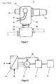
- the actuating drive 1 is equipped with an electrical controller 13, which is flange-connected to the gearbox 12. Furthermore, a connection box 17 is provided for connecting cables to the power supply 14 and for feeding in control signals 15, and is mounted on the gearbox 12.
- Figure 2 illustrates the basic power flow in the actuating drive 1.
- the electrical controller 13 is a frequency converter 19, which is connected to the power supply 14.
- the power supply 14 is formed by the public AC mains system.
- the three-phase AC voltage, at a fixed frequency and fixed amplitude, is converted by the frequency converter 19, and as a function of control signals 15, into a three-phase AC voltage at a variable frequency f with a variable amplitude U .
- the control signals 15 are limited to clockwise running and anticlockwise running of the electric motor 11, and the electric motor 11 being at rest.
- the output voltage of the frequency converter 19 is connected to the stator windings of the three-phase asynchronous motor 11.
- the rotation speed n of the rotor of the electric motor 11 is set by the frequency f, where n ⁇ f and the torque M at the given frequency f, by means of the amplitude U of the output voltage where M ⁇ U 2 / f 2 .
- the correlation of these values is stored in the electrical controller 13.
- the rotor shaft of the electric motor 11 is mechanically coupled to the input drive train of the gearbox 12, and the output drive train of the gearbox 12 is mechanically coupled to the fitting 16.
- the temperature ⁇ of the actuating drive 1 is monitored by at least one temperature sensor 18.
- a first embodiment provides for the temperature ⁇ of the actuating drive 1 to be measured on the gearbox 12.
- the heating of the actuating drive 1 resulting from the high power losses in the gearbox 12 when it is loaded dynamically is advantageously detected, this being at least half of the power supplied by the electric motor 11.
- a second embodiment provides for the temperature ⁇ of the actuating drive 1 to be measured on the electric motor 11.
- the heating of the actuating drive 1 resulting from resistive losses in the windings of the electric motor 11 when loaded in the steady state is advantageously detected, and occurs when the fitting 16 is jammed.
- a third embodiment provides for the temperature ⁇ of the actuating drive 1 to be measured on the electric motor 11 and on the gearbox 12.
- both the heating of the actuating drive 1 due to the high power losses in the gearbox 12 when it is loaded dynamically and the heating of the actuating drive 1 resulting from the resistive losses in the windings of the electric motor 11 when it is loaded in the steady state are advantageously detected.
- the further processing is in this case governed by the respectively higher measured temperature.
- the rotation speed n of the electric motor 11 is reduced as a function of the measured temperature ⁇ , while the torque M is kept constant.
- the power supplied to the gearbox 12 is proportional to the product of the torque M and the rotation speed n on the input drive train P ⁇ M * n. In consequence, the power supplied to the gearbox 12 falls in proportion to the reduction in the rotation speed n.
- the power losses converted into heat in the gearbox 12 also fall in proportion to the reduction in the rotation speed n .
- Figure 3 shows the power losses P v in the gearbox 12 for a given efficiency ⁇ as a function of the rotation speed n for various torques M 1 to M 3 where M 1 > M 2 > M 3 .
- the reference symbol P G in this case denotes precisely the power loss P v , whose equivalent amount of heat is emitted via the surface of the gearbox 12 to the environment, while maintaining a constant gearbox temperature.
- the rotation speed n on the input drive train of the gearbox 12 is equal to the rotation speed n of the rotor shaft of the electric motor 11.
- the rotation speed n of the rotor shaft of the electric motor 11 is set via the frequency f of the output voltage of the frequency converter 19.
- the torque M at a given frequency f ⁇ n is set by the amplitude U of the output voltage, where M ⁇ U 2 / f 2 , depending on the control task from the surrounding process installation.
- Figure 4 shows a characteristic of the relationship between the torque of the motor and the amplitude U and frequency f of the output voltage of the frequency converter 19 for various torques M 1 to M 3 where M 1 > M 2 > M 3 .
- the association between the rotation speed n 1 to n 3 and each torque M 1 to M 3 result, via the relationship f ⁇ n in frequencies f 1 to f 3 , where one frequency f 1 to f 3 , and only one such frequency, is associated with each torque M 1 to M 3 .
- the associated amplitude U 1 , U 2 and U 3 of the output voltage is determined using the relationship between the torque M ⁇ U 2 / f 2 and the frequency f ⁇ n and amplitude U of the output voltage for each rotation speed/torque pair n 1 / M 1 , n 2 / M 2 and n 3 / M 3 .
- the power loss P V P G which is acceptable to maintain a constant gearbox temperature is defined for each ambient temperature.
- the associated frequency f and amplitude U of the output voltage of the frequency converter 19 are described uniquely by a respective triple [ M , f, U ] for each torque M required by the control task. The totality of all the triples for a given actuating drive 1 are combined in a characteristic which is stored in the controller 13.
- the rotation speed n is chosen in a suitable way to limit the power loss in the gearbox 12 to a value which allows the amount of heat produced by the power losses to be dissipated via the surface of the gearbox 12 to the environment while maintaining a predetermined gearbox temperature.
- a preferred embodiment provides that the amplitude of the temperature of the actuating drive 1 is measured continuously and the rotation speed n is reduced continuously, in proportion to the temperature rise, while the torque M is kept constant.
- the rotation speed n is set by the frequency f
- the torque M to be maintained at a given frequency f is set by the amplitude U of the output voltage of the frequency converter 19.
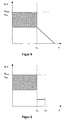
- Figure 5 shows the range of permissible amplitudes U and frequencies f plotted against the temperature of the actuating drive 1 for this purpose.
- a gearbox temperature 0 below the nominal value ⁇ n , ⁇ ⁇ ⁇ n , all the frequencies f ⁇ f max and amplitudes U ⁇ U max are permissible.
- gearbox temperatures ⁇ above the nominal value ⁇ n , ⁇ > ⁇ n each gearbox temperature ⁇ has one, and only one, associated frequency f and amplitude U for a predetermined torque M .
- the amount of heat produced for each temperature of the actuating drive 1 via the power losses is advantageously precisely that which is emitted to the environment while maintaining the present temperature.
- the fitting 16 is set to the respective maximum permissible movement rate, corresponding to the control task from the surrounding process installation.
- An alternative embodiment provides that, as soon as the continuously measured temperature ⁇ of the actuating drive 1 exceeds a predetermined nominal value ⁇ n , the rotation speed n is set to a reduced, fixed value which, for a torque M which is being kept constant, is selected such that a predetermined temperature limit value ⁇ G is reached as a maximum, but is not exceeded, during further operation of the actuating drive 1.
- the rotation speed n is set by the frequency f
- the torque M to be maintained at a given frequency f is set by the amplitude U of the output voltage of the frequency converter 19.
- Figure 6 shows the range of permissible amplitudes U and frequencies f, plotted against the temperature of the actuating drive 1, for this purpose. If the gearbox temperature ⁇ is below the nominal value ⁇ n , ⁇ ⁇ ⁇ n , all the frequencies f ⁇ f max and amplitudes U ⁇ U max are permissible. For gearbox temperatures ⁇ above the nominal value ⁇ n , ⁇ > ⁇ n , the frequency f and the amplitude U of the output voltage of the frequency converter 19 are set such that they are fixed for a given torque M .
Landscapes
- Engineering & Computer Science (AREA)
- Microelectronics & Electronic Packaging (AREA)
- Power Engineering (AREA)
- General Engineering & Computer Science (AREA)
- Mechanical Engineering (AREA)
- Control Of Ac Motors In General (AREA)
- Control Of Multiple Motors (AREA)
- Hydraulic Clutches, Magnetic Clutches, Fluid Clutches, And Fluid Joints (AREA)
Abstract
Description
- The invention relates to a method for operating an actuating drive for controlling fittings, having the features of the precharacterizing clause of
Patent Claim 1. - Such actuating drives are used for process automation in a process installation, in order to open and to close valves, flaps and the like.
- Such an actuating drive essentially comprises an electric motor, which moves a fitting with a predetermined torque via a self-locking gearbox. If the electric motor is overloaded, the motor windings are heated unacceptably, and this can lead to damage or destruction of the motor windings. Such overloads occur regularly if the fitting is jammed and the force disconnection fails at the same time.
- Furthermore, the problem that arises in particular with high-power actuating drives is that self-locking gearboxes become severely heated during continuous operation, due to their low efficiency. The thermal coupling between the electric motor and the gearbox results in the electric motor being heated further.
- In order to protect motor windings, it is known from the publication from the Auma Co. "Drehantriebe für Steuerbetrieb" [Rotary drives for control operation], Issue 2.96, for the circuit for feeding the electric motor to be interrupted as soon as the winding temperature exceeds a predetermined limit value. However, this procedure is subject to the disadvantage that, throughout the entire period during which an excessive temperature is identified, the fitting is locked in its most recently assumed position, no longer reacts to control commands, and the sequence in the surrounding process installation is thus interfered with.
- The invention is thus based on the object of specifying a method for operating an actuating drive for controlling fittings, which allows the actuating drive to be protected against unacceptable, destructive heating, and nevertheless allows operation of the surrounding process installation to be maintained, despite the excessive temperature.
- According to the invention, this object is achieved by the means in
Patent Claim 1. Advantageous refinements of the invention are specified in the subordinate Claims 2 to 7. - The invention is based on an actuating drive whose electric motor is connected to a frequency converter. Such frequency converters are generally known per se and are described, for example, in DE 42 35 223. During correct use, the frequency and the output voltage of the frequency converter are set in accordance with the control object from the surrounding process installation. In this case, the rotation speed of the electric motor is set by the frequency, and the torque which is required to move the given fitting in accordance with the control task is set by the output voltage at the given frequency.
- Depending on the load on the actuating drive, an amount of heat is produced in the actuating drive which is caused essentially by mechanical friction and electrical power losses, and which is greater than the amount of heat which can be dissipated via the surface of the actuating drive to the environment, and this in consequence leads to an increase in the temperature of the actuating drive.
- According to the invention, the temperature of the actuating drive is monitored, and the rotation speed of the electric motor is reduced, as a function of the measured temperature, while the torque is kept constant. To this end, the motor voltage emitted from the frequency converter is reduced in accordance with a characteristic which can be predetermined, virtually in proportion to the stator frequency.
- If the torque is kept constant, the power supplied to the gearbox falls in proportion to the reduction in the drive rotation speed. The power losses which lead to heating of the gearbox fall in accordance with the efficiency η, which is governed by the gearbox design and, for self-locking gearboxes, is always η ≤ 0.5.
- The drive rotation speed is set so that the gearbox temperature caused by the power losses in the gearbox remains below the predetermined limit value. The actuating drive is advantageously protected against excessive temperature increases, while nevertheless remaining ready to operate during periods when the temperature is raised. This avoids disturbances in the operational sequence of the surrounding process installation.
- The invention is described in more detail in the following text with reference to exemplary embodiments. In the drawings which are required for this purpose:
- Figure 1
- shows an illustration of the fundamental design of an actuating drive
- Figure 2
- shows an outline illustration of the power flow in an actuating drive
- Figure 3
- shows a characteristic for the power losses from the gearbox as a function of the rotation speed and the torque
- Figure 4
- shows a characteristic to illustrate the relationship between the motor torque and the voltage and frequency
- Figure 5
- shows an illustration of permissible voltages and frequencies for the frequency converter, as a function of the temperature of the actuating drive, with continuous adaptation
- Figure 6
- shows an illustration of permissible voltages and frequencies of the frequency converter, as a function of the temperature of the actuating drive, with fixed adaptation.
- The actuating
drive 1 is equipped with anelectrical controller 13, which is flange-connected to thegearbox 12. Furthermore, aconnection box 17 is provided for connecting cables to thepower supply 14 and for feeding incontrol signals 15, and is mounted on thegearbox 12. - Using the same reference symbols for the same means, Figure 2 illustrates the basic power flow in the actuating
drive 1. In this case, theelectrical controller 13 is afrequency converter 19, which is connected to thepower supply 14. Thepower supply 14 is formed by the public AC mains system. The three-phase AC voltage, at a fixed frequency and fixed amplitude, is converted by thefrequency converter 19, and as a function ofcontrol signals 15, into a three-phase AC voltage at a variable frequency f with a variable amplitude U. For asimple actuating drive 1 for respectively completely opening and closing thefitting 16, thecontrol signals 15 are limited to clockwise running and anticlockwise running of theelectric motor 11, and theelectric motor 11 being at rest. - The output voltage of the
frequency converter 19 is connected to the stator windings of the three-phaseasynchronous motor 11. The rotation speed n of the rotor of theelectric motor 11 is set by the frequency f, where n ∼ f and the torque M at the given frequency f, by means of the amplitude U of the output voltage where M ∼ U2 / f2. The correlation of these values is stored in theelectrical controller 13. - The rotor shaft of the
electric motor 11 is mechanically coupled to the input drive train of thegearbox 12, and the output drive train of thegearbox 12 is mechanically coupled to thefitting 16. - While the actuating
drive 1 is being used correctly, an amount of heat is produced in the actuating drive as a function of the load, which is caused in the self-locking gearbox 12 by the maximum efficiency of 50% due to mechanical friction, and in theelectric motor 11 essentially by resistive losses in the windings. In order to protect the actuatingdrive 1 against unacceptable, destructive heating, the temperature ϑ of the actuatingdrive 1 is monitored by at least onetemperature sensor 18. - A first embodiment provides for the temperature ϑ of the actuating
drive 1 to be measured on thegearbox 12. In this case, the heating of the actuatingdrive 1 resulting from the high power losses in thegearbox 12 when it is loaded dynamically is advantageously detected, this being at least half of the power supplied by theelectric motor 11. - A second embodiment provides for the temperature ϑ of the actuating
drive 1 to be measured on theelectric motor 11. In this case, the heating of the actuatingdrive 1 resulting from resistive losses in the windings of theelectric motor 11 when loaded in the steady state is advantageously detected, and occurs when thefitting 16 is jammed. - A third embodiment provides for the temperature ϑ of the actuating
drive 1 to be measured on theelectric motor 11 and on thegearbox 12. In this case, both the heating of the actuatingdrive 1 due to the high power losses in thegearbox 12 when it is loaded dynamically and the heating of the actuatingdrive 1 resulting from the resistive losses in the windings of theelectric motor 11 when it is loaded in the steady state are advantageously detected. The further processing is in this case governed by the respectively higher measured temperature. - The rotation speed n of the
electric motor 11 is reduced as a function of the measured temperature ϑ, while the torque M is kept constant. The power supplied to thegearbox 12 is proportional to the product of the torque M and the rotation speed n on the input drive train P ∼ M * n. In consequence, the power supplied to thegearbox 12 falls in proportion to the reduction in the rotation speed n. Thus, for a given efficiency η ≤ 0.5, the power losses converted into heat in thegearbox 12 also fall in proportion to the reduction in the rotation speed n. - To this end, Figure 3 shows the power losses P v in the
gearbox 12 for a given efficiency η as a function of the rotation speed n for various torques M1 to M3 where M1 > M2 > M3 . The reference symbol PG in this case denotes precisely the power loss Pv , whose equivalent amount of heat is emitted via the surface of thegearbox 12 to the environment, while maintaining a constant gearbox temperature. In accordance with the relationship P ∼ M * n, one and only one rotation speed n1 to n3 is associated with each torque M1 to M3 and, for a given temperature, the power loss at this rotation speed is PV = PG. - Accordingly, when the rotation speed n1 is set for a given torque M1, the power loss converted into heat is precisely PV = PG , which equivalent amount of heat is emitted via the surface of the
gearbox 12 to the environment while maintaining a constant gearbox temperature. The same applies to the rotation speed/torque pairs n2 / M2 and n3 / M3 for further given torques. Based on the relationship P ∼ M * n and verified by the illustration in Figure 3, it can be seen that greater rotation speeds n1 < n2 < n3 are permissible in order to limit the power loss PV to the power loss PV = PG which is permissible in order to maintain a constant gearbox temperature at relatively low torques M1 > M2 > M3 , and vice versa. - The rotation speed n on the input drive train of the
gearbox 12 is equal to the rotation speed n of the rotor shaft of theelectric motor 11. The rotation speed n of the rotor shaft of theelectric motor 11 is set via the frequency f of the output voltage of thefrequency converter 19. The torque M at a given frequency f ∼ n is set by the amplitude U of the output voltage, where M ∼ U2 / f2, depending on the control task from the surrounding process installation. - Figure 4 shows a characteristic of the relationship between the torque of the motor and the amplitude U and frequency f of the output voltage of the
frequency converter 19 for various torques M1 to M3 where M1 > M2 > M3 . The association between the rotation speed n1 to n3 and each torque M1 to M3 result, via the relationship f ∼ n in frequencies f1 to f3 , where one frequency f1 to f3 , and only one such frequency, is associated with each torque M1 to M3 . The associated amplitude U1 , U2 and U3 of the output voltage is determined using the relationship between the torque M ∼ U2 / f2 and the frequency f ∼ n and amplitude U of the output voltage for each rotation speed/torque pair n1 / M1 , n2 / M2 and n3 / M3 . - For a given
actuating drive 1 having a thermal transfer response to the environment which is determined by the design and is thus predetermined, the power loss PV = PG which is acceptable to maintain a constant gearbox temperature is defined for each ambient temperature. For the givenactuating drive 1, the associated frequency f and amplitude U of the output voltage of thefrequency converter 19 are described uniquely by a respective triple [M, f, U] for each torque M required by the control task. The totality of all the triples for a givenactuating drive 1 are combined in a characteristic which is stored in thecontroller 13. - The rotation speed n is chosen in a suitable way to limit the power loss in the
gearbox 12 to a value which allows the amount of heat produced by the power losses to be dissipated via the surface of thegearbox 12 to the environment while maintaining a predetermined gearbox temperature. - To this end, a preferred embodiment provides that the amplitude of the temperature of the
actuating drive 1 is measured continuously and the rotation speed n is reduced continuously, in proportion to the temperature rise, while the torque M is kept constant. In this case, the rotation speed n is set by the frequency f, and the torque M to be maintained at a given frequency f is set by the amplitude U of the output voltage of thefrequency converter 19. - Figure 5 shows the range of permissible amplitudes U and frequencies f plotted against the temperature of the
actuating drive 1 for this purpose. For a gearbox temperature 0 below the nominal value ϑn, ϑ < ϑn, all the frequencies f ≤ f max and amplitudes U ≤ U max are permissible. For gearbox temperatures ϑ above the nominal value ϑn, ϑ > ϑn, each gearbox temperature ϑ has one, and only one, associated frequency f and amplitude U for a predetermined torque M. - In this case, the amount of heat produced for each temperature of the
actuating drive 1 via the power losses is advantageously precisely that which is emitted to the environment while maintaining the present temperature. In consequence, at all temperatures, the fitting 16 is set to the respective maximum permissible movement rate, corresponding to the control task from the surrounding process installation. - An alternative embodiment provides that, as soon as the continuously measured temperature ϑ of the
actuating drive 1 exceeds a predetermined nominal value ϑn, the rotation speed n is set to a reduced, fixed value which, for a torque M which is being kept constant, is selected such that a predetermined temperature limit value ϑG is reached as a maximum, but is not exceeded, during further operation of theactuating drive 1. In this case, the rotation speed n is set by the frequency f, and the torque M to be maintained at a given frequency f is set by the amplitude U of the output voltage of thefrequency converter 19. - Figure 6 shows the range of permissible amplitudes U and frequencies f, plotted against the temperature of the
actuating drive 1, for this purpose. If the gearbox temperature ϑ is below the nominal value ϑn, ϑ < ϑn, all the frequencies f ≤ f max and amplitudes U ≤ U max are permissible. For gearbox temperatures ϑ above the nominal value ϑn, ϑ > ϑn, the frequency f and the amplitude U of the output voltage of thefrequency converter 19 are set such that they are fixed for a given torque M. - List of reference symbols
- 1
- Actuating drive
- 11
- Electric motor
- 12
- Gearbox
- 13
- Controller
- 14
- Power supply
- 15
- Control signals
- 16
- Fitting
- 17
- Connection box
- 18
- Temperature sensor
- 19
- Frequency converter
- 20
- Transport tube
Claims (7)
- Method for operating an actuating drive for controlling fittings, in which case the actuating drive has an electric motor which is fed from a frequency converter and moves a fitting with a predetermined torque via a self-locking gearbox,
characterized in that
the temperature ϑ of the actuating drive (1) is measured during continuous operation, and the rotation speed n of the electric motor (11) is reduced as a function of the measured temperature ϑ while maintaining the torque M, by reducing the amplitude U and the frequency f of the output voltage of the frequency converter (19) in proportion to one another. - Method according to Claim 1,
characterized in that
the amplitude of the temperature ϑ of the actuating drive (1) is measured continuously, and the rotation speed n is reduced continuously, in proportion to the temperature rise while the torque M is being kept constant. - Method according to Claim 1,
characterized in that
the amplitude of the temperature ϑ of the actuating drive (1) is measured continuously, and, while the torque M is being kept constant, the rotation speed n is set to a reduced, fixed value as soon as the continuously measured temperature ϑ of the actuating drive (1) exceeds a predetermined nominal value ϑn. - Method according to one of Claims 1 to 3,
characterized in that
the temperature ϑ of the actuating drive (1) is measured on the gearbox (12). - Method according to one of Claims 1 to 3,
characterized in that
the temperature ϑ of the actuating drive (1) is measured on the electric motor (11). - Method according to one of Claims 1 to 5,
characterized in that
the temperature ϑ of the actuating drive (1) is measured on the electric motor (11) and on the gearbox (12). - Method according to one of Claims 1 to 6,
characterized in that
any increase in the temperature ϑ of the actuating drive (1) identified on the electric motor (11) and/or on the gearbox (12) is signalled to a remote control station.
Applications Claiming Priority (2)
| Application Number | Priority Date | Filing Date | Title |
|---|---|---|---|
| DE10000182A DE10000182C1 (en) | 2000-01-05 | 2000-01-05 | Method for operating an adjusting driving mechanism for controlling armatures has a frequency transformer feeding an electric motor to adjust an armature with a preset torque by using an irreversible gearbox. |
| DE10000182 | 2000-01-05 |
Publications (3)
| Publication Number | Publication Date |
|---|---|
| EP1115188A2 true EP1115188A2 (en) | 2001-07-11 |
| EP1115188A3 EP1115188A3 (en) | 2005-08-31 |
| EP1115188B1 EP1115188B1 (en) | 2008-09-03 |
Family
ID=7626777
Family Applications (1)
| Application Number | Title | Priority Date | Filing Date |
|---|---|---|---|
| EP00127901A Expired - Lifetime EP1115188B1 (en) | 2000-01-05 | 2000-12-20 | Method for operating an actuating device |
Country Status (3)
| Country | Link |
|---|---|
| US (1) | US6424108B1 (en) |
| EP (1) | EP1115188B1 (en) |
| DE (2) | DE10000182C1 (en) |
Cited By (2)
| Publication number | Priority date | Publication date | Assignee | Title |
|---|---|---|---|---|
| FR2830309A1 (en) * | 2001-10-02 | 2003-04-04 | Renault | DEVICE FOR CORRECTING THE TORQUE CONSTANT OF AN ELECTRIC ACTUATOR |
| RU2659806C1 (en) * | 2017-03-20 | 2018-07-04 | Публичное акционерное общество "Транснефть" (ПАО "Транснефть") | Electric drive control device |
Families Citing this family (5)
| Publication number | Priority date | Publication date | Assignee | Title |
|---|---|---|---|---|
| DE10142732A1 (en) * | 2001-08-31 | 2003-03-20 | Hilti Ag | Circuit and method for speed control of universal electric motors |
| DE10149479A1 (en) * | 2001-10-08 | 2003-04-10 | Siemens Ag | Actuator for automotive functional parts with a switchable self-locking gear |
| DE10242727B4 (en) * | 2002-09-13 | 2008-01-10 | First, Franc | Valve |
| CN108779868B (en) * | 2016-03-09 | 2020-03-06 | 三菱电机株式会社 | Valve device |
| US10007273B2 (en) * | 2016-04-27 | 2018-06-26 | Cameron International Corporation | Variable frequency drive for a fluid-handling system |
Family Cites Families (13)
| Publication number | Priority date | Publication date | Assignee | Title |
|---|---|---|---|---|
| US4590413A (en) * | 1982-01-11 | 1986-05-20 | Eaton Corporation | EV drivetrain inverter with V/HZ optimization |
| US4644239A (en) * | 1984-06-07 | 1987-02-17 | Kabushiki Kaisha Sankyo Seiki Seisakusho | Motor actuator with control means responsive to internal and external conditions |
| DE3731469A1 (en) * | 1987-09-18 | 1989-04-06 | Siemens Ag | ELECTRIC MOTOR DRIVE DRIVE |
| US4953053A (en) * | 1989-01-31 | 1990-08-28 | Harnischfeger Corporation | Method and apparatus for detecting mechanical overload of a hoist |
| DE4010049C1 (en) * | 1990-03-29 | 1991-10-10 | Grundfos International A/S, Bjerringbro, Dk | Pump unit for heating or cooling circuit - uses frequency regulator to reduce rotation of pump motor upon detected overheating |
| GB2255866B (en) * | 1991-05-14 | 1995-08-02 | Rotork Controls | An actuactor and an electric motor drive system |
| DE4235223C1 (en) * | 1992-10-13 | 1993-11-11 | Licentia Gmbh | Operating and braking circuit for several AC motors coupled via load - has single brake switch connecting braking resistance bridged by free-running diode across DC voltage rail pair supplying all motors |
| US5444344A (en) * | 1993-09-01 | 1995-08-22 | Beloit Technologies, Inc. | System for controlling variable frequency driver for AC motor including selectable speed signals |
| US6121735A (en) * | 1994-03-10 | 2000-09-19 | Igeta; Tamotsu | Actuator with start-stop operation |
| JP3430773B2 (en) * | 1996-02-21 | 2003-07-28 | 株式会社明電舎 | Overheating protection method of switching element in inverter device |
| US5838133A (en) * | 1997-05-14 | 1998-11-17 | Mccann; Roy A. | Switched reluctance motor controller |
| US5977740A (en) * | 1997-05-14 | 1999-11-02 | Itt Manufacturing Enterprises, Inc. | Brake-by-wire system with switched reluctance motor controller |
| DE29717431U1 (en) * | 1997-09-30 | 1999-01-28 | Sirona Dental Systems GmbH & Co. KG, 64625 Bensheim | Circuit arrangement for protecting a small electric motor of a dental drill drive against overload |
-
2000
- 2000-01-05 DE DE10000182A patent/DE10000182C1/en not_active Expired - Fee Related
- 2000-12-20 US US09/742,630 patent/US6424108B1/en not_active Expired - Fee Related
- 2000-12-20 EP EP00127901A patent/EP1115188B1/en not_active Expired - Lifetime
- 2000-12-20 DE DE60040133T patent/DE60040133D1/en not_active Expired - Lifetime
Non-Patent Citations (1)
| Title |
|---|
| None |
Cited By (2)
| Publication number | Priority date | Publication date | Assignee | Title |
|---|---|---|---|---|
| FR2830309A1 (en) * | 2001-10-02 | 2003-04-04 | Renault | DEVICE FOR CORRECTING THE TORQUE CONSTANT OF AN ELECTRIC ACTUATOR |
| RU2659806C1 (en) * | 2017-03-20 | 2018-07-04 | Публичное акционерное общество "Транснефть" (ПАО "Транснефть") | Electric drive control device |
Also Published As
| Publication number | Publication date |
|---|---|
| EP1115188A3 (en) | 2005-08-31 |
| US20020067149A1 (en) | 2002-06-06 |
| EP1115188B1 (en) | 2008-09-03 |
| DE10000182C1 (en) | 2001-02-15 |
| US6424108B1 (en) | 2002-07-23 |
| DE60040133D1 (en) | 2008-10-16 |
Similar Documents
| Publication | Publication Date | Title |
|---|---|---|
| US8547050B2 (en) | Control method and system with feedback indicative of load flux | |
| EP2313674B1 (en) | Variable speed actuator | |
| Dubey | Fundamentals of electrical drives | |
| KR100941681B1 (en) | Control device for air-conditioning and ventilation facilities or pump motor | |
| EP2709266B1 (en) | Voltage control in a doubly-fed induction generator wind turbine system | |
| EP2682339B1 (en) | Power distribution systems | |
| EP1768223A2 (en) | Method for operation of a converter system | |
| US20170130856A1 (en) | Variable-speed actuator | |
| KR20030090727A (en) | Method for operating a wind energy plant | |
| EP1115188B1 (en) | Method for operating an actuating device | |
| US10935111B2 (en) | Superposition gear for a drive system | |
| US8138709B2 (en) | Control method and system | |
| CA2213202A1 (en) | Drive having a three-phase asynchronous motor with slip ring rotor | |
| US7023712B2 (en) | Cooling arrangement in frequency converter | |
| US6127791A (en) | Electric drive system and method | |
| JP4265932B2 (en) | Motor control device | |
| KR102760645B1 (en) | Apparatus and method for controlling inverter | |
| US20250007276A1 (en) | Torque protection mechanism for brushless motors | |
| Cookson et al. | Adjustable speed drives applied to large AC induction motor and pump systems | |
| RU2412526C1 (en) | Variable-frequency control device of asynchronous electric motor | |
| CN114026763B (en) | Method for feeding in electric power by means of wind farms | |
| Bulatbayeva et al. | Introduction of Frequency Control of Electric Drives of the Dust Supply System of the Boiler Unit | |
| RU2146331C1 (en) | Device for operational control of ventilation setup | |
| RU2417501C1 (en) | Method to control asynchronous generator during parallel operation with grid and device for its realisation | |
| Gärtner et al. | The speed control of the induction motors by the change of supply voltage |
Legal Events
| Date | Code | Title | Description |
|---|---|---|---|
| PUAI | Public reference made under article 153(3) epc to a published international application that has entered the european phase |
Free format text: ORIGINAL CODE: 0009012 |
|
| AK | Designated contracting states |
Kind code of ref document: A2 Designated state(s): AT BE CH CY DE DK ES FI FR GB GR IE IT LI LU MC NL PT SE TR |
|
| AX | Request for extension of the european patent |
Free format text: AL;LT;LV;MK;RO;SI |
|
| RIC1 | Information provided on ipc code assigned before grant |
Free format text: 7H 04N 5/445 A |
|
| PUAL | Search report despatched |
Free format text: ORIGINAL CODE: 0009013 |
|
| AK | Designated contracting states |
Kind code of ref document: A3 Designated state(s): AT BE CH CY DE DK ES FI FR GB GR IE IT LI LU MC NL PT SE TR |
|
| AX | Request for extension of the european patent |
Extension state: AL LT LV MK RO SI |
|
| RIC1 | Information provided on ipc code assigned before grant |
Ipc: 7H 02H 5/04 B Ipc: 7H 02H 7/085 A Ipc: 7H 02P 7/00 B |
|
| 17P | Request for examination filed |
Effective date: 20060228 |
|
| AKX | Designation fees paid |
Designated state(s): DE FR GB IT |
|
| GRAP | Despatch of communication of intention to grant a patent |
Free format text: ORIGINAL CODE: EPIDOSNIGR1 |
|
| GRAS | Grant fee paid |
Free format text: ORIGINAL CODE: EPIDOSNIGR3 |
|
| GRAA | (expected) grant |
Free format text: ORIGINAL CODE: 0009210 |
|
| RAP1 | Party data changed (applicant data changed or rights of an application transferred) |
Owner name: ABB AG |
|
| AK | Designated contracting states |
Kind code of ref document: B1 Designated state(s): DE FR GB IT |
|
| REG | Reference to a national code |
Ref country code: GB Ref legal event code: FG4D |
|
| REF | Corresponds to: |
Ref document number: 60040133 Country of ref document: DE Date of ref document: 20081016 Kind code of ref document: P |
|
| PLBE | No opposition filed within time limit |
Free format text: ORIGINAL CODE: 0009261 |
|
| STAA | Information on the status of an ep patent application or granted ep patent |
Free format text: STATUS: NO OPPOSITION FILED WITHIN TIME LIMIT |
|
| 26N | No opposition filed |
Effective date: 20090604 |
|
| GBPC | Gb: european patent ceased through non-payment of renewal fee |
Effective date: 20081220 |
|
| PG25 | Lapsed in a contracting state [announced via postgrant information from national office to epo] |
Ref country code: IT Free format text: LAPSE BECAUSE OF FAILURE TO SUBMIT A TRANSLATION OF THE DESCRIPTION OR TO PAY THE FEE WITHIN THE PRESCRIBED TIME-LIMIT Effective date: 20080903 |
|
| REG | Reference to a national code |
Ref country code: FR Ref legal event code: ST Effective date: 20090831 |
|
| PG25 | Lapsed in a contracting state [announced via postgrant information from national office to epo] |
Ref country code: GB Free format text: LAPSE BECAUSE OF NON-PAYMENT OF DUE FEES Effective date: 20081220 |
|
| PG25 | Lapsed in a contracting state [announced via postgrant information from national office to epo] |
Ref country code: FR Free format text: LAPSE BECAUSE OF NON-PAYMENT OF DUE FEES Effective date: 20081231 |
|
| PGFP | Annual fee paid to national office [announced via postgrant information from national office to epo] |
Ref country code: DE Payment date: 20111222 Year of fee payment: 12 |
|
| REG | Reference to a national code |
Ref country code: DE Ref legal event code: R119 Ref document number: 60040133 Country of ref document: DE Effective date: 20130702 |
|
| PG25 | Lapsed in a contracting state [announced via postgrant information from national office to epo] |
Ref country code: DE Free format text: LAPSE BECAUSE OF NON-PAYMENT OF DUE FEES Effective date: 20130702 |