EP1115183A1 - Movable terminal, coaxial connector, and communications apparatus incorporating the same - Google Patents
Movable terminal, coaxial connector, and communications apparatus incorporating the same Download PDFInfo
- Publication number
- EP1115183A1 EP1115183A1 EP01400033A EP01400033A EP1115183A1 EP 1115183 A1 EP1115183 A1 EP 1115183A1 EP 01400033 A EP01400033 A EP 01400033A EP 01400033 A EP01400033 A EP 01400033A EP 1115183 A1 EP1115183 A1 EP 1115183A1
- Authority
- EP
- European Patent Office
- Prior art keywords
- movable
- terminal
- coaxial connector
- contact
- insulating case
- Prior art date
- Legal status (The legal status is an assumption and is not a legal conclusion. Google has not performed a legal analysis and makes no representation as to the accuracy of the status listed.)
- Granted
Links
- 238000004891 communication Methods 0.000 title claims abstract description 11
- 239000004020 conductor Substances 0.000 claims description 6
- 238000009434 installation Methods 0.000 claims description 3
- 239000002184 metal Substances 0.000 abstract description 7
- 229920003002 synthetic resin Polymers 0.000 abstract description 2
- 239000000057 synthetic resin Substances 0.000 abstract description 2
- 238000005452 bending Methods 0.000 description 5
- 230000004907 flux Effects 0.000 description 3
- 238000004080 punching Methods 0.000 description 3
- 229910000679 solder Inorganic materials 0.000 description 3
- 238000010586 diagram Methods 0.000 description 2
- 230000000694 effects Effects 0.000 description 2
- 238000004519 manufacturing process Methods 0.000 description 2
- 238000005259 measurement Methods 0.000 description 2
- 239000000523 sample Substances 0.000 description 2
- 229910001220 stainless steel Inorganic materials 0.000 description 2
- 239000010935 stainless steel Substances 0.000 description 2
- 229910001369 Brass Inorganic materials 0.000 description 1
- 229910000906 Bronze Inorganic materials 0.000 description 1
- OAICVXFJPJFONN-UHFFFAOYSA-N Phosphorus Chemical compound [P] OAICVXFJPJFONN-UHFFFAOYSA-N 0.000 description 1
- 239000010951 brass Substances 0.000 description 1
- 239000010974 bronze Substances 0.000 description 1
- KUNSUQLRTQLHQQ-UHFFFAOYSA-N copper tin Chemical compound [Cu].[Sn] KUNSUQLRTQLHQQ-UHFFFAOYSA-N 0.000 description 1
- 230000006866 deterioration Effects 0.000 description 1
- 230000002542 deteriorative effect Effects 0.000 description 1
- 238000006073 displacement reaction Methods 0.000 description 1
- 230000007246 mechanism Effects 0.000 description 1
- 238000000034 method Methods 0.000 description 1
- 238000010295 mobile communication Methods 0.000 description 1
- 238000012986 modification Methods 0.000 description 1
- 230000004048 modification Effects 0.000 description 1
- 238000000465 moulding Methods 0.000 description 1
- 230000008569 process Effects 0.000 description 1
- 229920005989 resin Polymers 0.000 description 1
- 239000011347 resin Substances 0.000 description 1
Images



Classifications
-
- H—ELECTRICITY
- H01—ELECTRIC ELEMENTS
- H01H—ELECTRIC SWITCHES; RELAYS; SELECTORS; EMERGENCY PROTECTIVE DEVICES
- H01H13/00—Switches having rectilinearly-movable operating part or parts adapted for pushing or pulling in one direction only, e.g. push-button switch
- H01H13/02—Details
- H01H13/12—Movable parts; Contacts mounted thereon
-
- H—ELECTRICITY
- H01—ELECTRIC ELEMENTS
- H01R—ELECTRICALLY-CONDUCTIVE CONNECTIONS; STRUCTURAL ASSOCIATIONS OF A PLURALITY OF MUTUALLY-INSULATED ELECTRICAL CONNECTING ELEMENTS; COUPLING DEVICES; CURRENT COLLECTORS
- H01R13/00—Details of coupling devices of the kinds covered by groups H01R12/70 or H01R24/00 - H01R33/00
- H01R13/66—Structural association with built-in electrical component
- H01R13/70—Structural association with built-in electrical component with built-in switch
- H01R13/703—Structural association with built-in electrical component with built-in switch operated by engagement or disengagement of coupling parts, e.g. dual-continuity coupling part
- H01R13/7031—Shorting, shunting or bussing of different terminals interrupted or effected on engagement of coupling part, e.g. for ESD protection, line continuity
- H01R13/7033—Shorting, shunting or bussing of different terminals interrupted or effected on engagement of coupling part, e.g. for ESD protection, line continuity making use of elastic extensions of the terminals
-
- H—ELECTRICITY
- H01—ELECTRIC ELEMENTS
- H01R—ELECTRICALLY-CONDUCTIVE CONNECTIONS; STRUCTURAL ASSOCIATIONS OF A PLURALITY OF MUTUALLY-INSULATED ELECTRICAL CONNECTING ELEMENTS; COUPLING DEVICES; CURRENT COLLECTORS
- H01R24/00—Two-part coupling devices, or either of their cooperating parts, characterised by their overall structure
- H01R24/38—Two-part coupling devices, or either of their cooperating parts, characterised by their overall structure having concentrically or coaxially arranged contacts
- H01R24/40—Two-part coupling devices, or either of their cooperating parts, characterised by their overall structure having concentrically or coaxially arranged contacts specially adapted for high frequency
- H01R24/42—Two-part coupling devices, or either of their cooperating parts, characterised by their overall structure having concentrically or coaxially arranged contacts specially adapted for high frequency comprising impedance matching means or electrical components, e.g. filters or switches
- H01R24/46—Two-part coupling devices, or either of their cooperating parts, characterised by their overall structure having concentrically or coaxially arranged contacts specially adapted for high frequency comprising impedance matching means or electrical components, e.g. filters or switches comprising switches
-
- H—ELECTRICITY
- H01—ELECTRIC ELEMENTS
- H01R—ELECTRICALLY-CONDUCTIVE CONNECTIONS; STRUCTURAL ASSOCIATIONS OF A PLURALITY OF MUTUALLY-INSULATED ELECTRICAL CONNECTING ELEMENTS; COUPLING DEVICES; CURRENT COLLECTORS
- H01R2103/00—Two poles
Definitions
- the present invention relates to movable terminals, coaxial connectors, and communications apparatuses incorporating the same.
- spring used in references to “springing properties”, “spring movable functions”, “spring supporting portions”, and the like, does not refer limitatively to a mechanical spring but denotes, more generally, items having “springiness”, “elasticity” or “resilience”.
- a conventional movable terminal 155 includes a movable mechanical portion 151 having a spring movable function and a lead portion 152 bent in a U-shape connected to the movable mechanical portion 151.
- the movable mechanical portion 151 includes an arm 151a extending to right-and-left sides from the lead portion 152, two spring supporting portions 151b formed at the ends of the arm 151a, a spring movable portion 151c extending substantially parallel to the arms 151a in such a manner that the portion 151c straddles the spring supporting portions 151b, and a contact portion 151d protruding from the spring movable portion 151c.
- Both ends of the spring movable portion 151c are supported and fixed by the spring supporting portions 151b.
- the central part of the spring movable portion 151c is curved in a circular form so as to extend upwardly.
- the contact portion 151d abuts with the lower surface of a contact part 141 of a fixed terminal 140, and thereby the fixed terminal 140 makes contact with the movable terminal 155 to be connected to each other.
- the conventional movable terminal 155 has only one arm 151a and only two bent parts A and B.
- plastic deformation of the movable terminal 155 occurs, thereby deteriorating the springing property. That is, after removing the counterpart coaxial connector, the fixed terminal 140 and the movable terminal 155 cannot be contacted and connected in a stable manner. In some cases, both terminals 140 and 155 can remain non-contact.
- the present invention provides a movable terminal including a frame-shaped portion, a resilient movable portion having both ends supported by the frame-shaped portion and having a displaceable resilient central part, and a contact portion integrally formed with the resilient movable portion and adapted to make contact with a fixed terminal so that the contact portion is connected to the fixed terminal, in which two arms arranged in parallel to the resilient movable portion of the frame-shaped portion are bent such that the resilient movable portion is curved in a circular, or convexly-curved, shape.
- the contact portion is formed on the top of the resilient movable portion curved in the circular shape.
- the present invention further provides a coaxial connector including an insulating case having a cavity in which the central contact of a counterpart coaxial connector is inserted, the movable terminal disposed in the cavity of the insulating case such that the movable terminal protrudes in a direction substantially perpendicular to a direction in which the central contact is inserted, a fixed terminal disposed in the cavity of the insulating case to make contact with a contact portion of the movable terminal so that the fixed terminal is connected to the contact portion, and an external terminal disposed on the outside of the insulating case to be electrically connected to an external conductor of the counterpart coaxial connector, in which the contact portion of the movable terminal and the fixed terminal separate from each other and make contact to be connected to each other in accordance with the installation and removal of the counterpart coaxial connector.
- the frame-shaped portion Since the frame-shaped portion has a high mechanical strength, the plastic deformation of the movable terminal hardly occurs even though the movable terminal is repeatedly pressed into contact with the central contact of the counterpart coaxial connector. As a result, the deterioration of springing property (elasticity) can be prevented. Moreover, the resilient movable portion is curved in the circular form by bending a flat plate instead of curving by plastic deformation. Thus, plastic deformation is more unlikely to occur.
- the present invention provides a communications apparatus incorporating the above coaxial connector, thereby having high reliability.
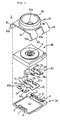
- FIG. 1 is an exploded perspective view showing the structure of a coaxial connector according to an embodiment of the present invention.
- a coaxial connector (coaxial receptacle) 1 is composed of a synthetic resin insulating case split into a lower insulating case 2A and an upper insulating case 2B, a metal fixed terminal 21, a metal movable terminal 31, and a metal external terminal (an external conductor) 41.
- the lower insulating case 2A has substantially a rectangular shape. At each of the two comers of one side of the upper surface (a split surface) of the lower insulating case 2A, a guide protrusion 3 for positioning the upper insulating case 2B is disposed. Near each of the guide protrusions 3, and on the opposite side of the lower insulating case 2A , cavity-like leg-receiving portions 4 for fitting the legs (not shown) of the upper insulating case 2B are provided. In addition, rectangular cut-away portions 6 and 7 are formed at the central parts of the mutually opposing edges of the lower insulating case 2A. The cut-away portion 6 contains a lead portion 24 (which will be described below) of the fixed terminal 21.
- the cut-away portion 7 contains a lead portion 34 (which will be described below) of the movable terminal 31.
- the dimensions of the cut-away portions 6 and 7 are set such that there is formed a clearance sufficient for preventing capillary effect due to the flux of solder used for mounting between the lower insulating case 2A and the lead portion 24 of the terminal 21 and the lead portion 34 of the terminal 31.
- the upper insulating case 2B is substantially rectangular.
- An entrance hole 13 having a round cross section is formed in the center of the upper insulating case 2B.
- the entrance hole 13 penetrates the upper insulating case 2B.
- the central contact of a counterpart coaxial connector is supposed to be inserted into the entrance hole 13.
- a groove 15 (see Fig. 7) having a V-shaped cross section is formed between the entrance hole 13 and an edge on which the fixed terminal 21 is led out.
- the groove 15 extends in a direction substantially perpendicular to the direction in which the fixed terminal 21 is led out.
- the fixed terminal 21 is typically formed by punching and bending a metal plate such as a flat stainless steel plate.
- the fixed terminal 21 is composed of a contact portion 22 with which the movable terminal 31 comes into contact, a fixed portion 23 sandwiched by the insulating cases 2A and 2B, and a lead portion 24 bent in an L-shape. Both sides of the contact portion 22 are folded at predetermined angles to form a horizontal face 22a and inclined faces 22b on each side of the horizontal face 22a.
- a round hole 26a and an oval hole 26b At the sides of the fixed portion 23 are formed a round hole 26a and an oval hole 26b.
- the legs of the upper insulating case 2B are fitted into the holes 26a and 26b, and the fixed terminal 21 is attached with the upper insulating case 2B with good positional accuracy with reference to the round hole 26a.
- the hole 26b has an oval shape in order to allow for production margin errors.
- the fixed terminal 21 is attached such that the horizontal face 22a of the contact portion 22 and the fixed portion 23 are in close contact with the bottom of the upper insulating case 2B.
- a clearance is provided at a part where the fixed terminal 21 crosses with the groove 15.
- the lead portion 24 is downwardly extended substantially in parallel to a side surface of the lower insulating case 2A.
- the top end of the lead portion 24 is inwardly bent at an angle of substantially 90 degrees so that the top portion is flush with the bottom surface of the lower insulating case 2A.
- the lead portion 24 serves as a soldered part.
- the movable terminal 31 is typically formed by punching and bending a metal plate such as a stainless steel plate having springing property in a predetermined shape. As shown in Figs. 2 to 5, the movable terminal 31 is composed of a movable contact portion 32 having a spring movable function and serves as a contact point with the fixed terminal 21, a fixed portion 33 attached in the insulating cases 2A and 2B, and a lead portion 34 bent in an L-shape.
- the movable contact portion 32 includes a frame-shaped portion 37, a spring movable (resilient) portion 38 whose both ends are supported by the frame-shaped portion 37, and a contact portion 39 disposed at the center of the spring movable portion 38.
- the structure of the substantially rectangular frame-shaped portion 37 has a high mechanical strength, and plastic deformation thereby hardly occurs.
- the frame-shaped portion 37 is composed of two spring supporting portions 37b connecting to the spring movable portion 38 and extending in a direction substantially perpendicular to the spring movable portion 38, and two arms 37a arranged substantially parallel to the spring movable portion 38.
- the spring movable portion 38 curves such that the portion 38 bulges upwardly in a circular shape, and has a desirable height at the top thereof.
- the contact portion 39 is provided on the top of the spring movable portion 38 curved in the circular shape.
- the curve of the spring movable portion 38 is formed by folding the two arms 37a at four positions A, B, C, and D so that the centers of the two arms 37a downwardly bulge.
- the spring movable portion 38 maintains the curve obtained by bending a flat plate without using a curve due to plastic deformation.
- the spring movable portion 38 only reverses to be back to an initial flat configuration. Therefore, even though attachment and detachment of the counterpart coaxial connector are repeated, the plastic deformation of the spring movable portion 38 is more unlikely to occur.
- a round hole 36a and an oval hole 36b are formed at the sides of the fixed portion 33.
- the movable terminal 31 is attached to the upper insulating case 2B with accurate position. In this case, the movable terminal 31 is attached in a state in which the fixed portion 33 is closely attached to the bottom of the upper insulating case 2B.
- the lead portion 34 is downwardly extended substantially in parallel to a side of the lower insulating case 2A.
- the top end of the lead portion 34 is inwardly bent at an angle of substantially 90 degrees so that the top end thereof is flush with the bottom of the lower insulating case 2A to be used as a soldered part.
- the external terminal 41 in contact with the external conductor of the counterpart coaxial connector is typically formed by punching, bending, and drawing a plate of metal such as brass and spring phosphor bronze.
- a flat portion 42 of the center of the plate is disposed over the upper surface of the upper insulating case 2B.
- a leg 43 is disposed at each of the four corners of the flat portion 42.
- the legs 43 are folded along the side surfaces and bottom surface of an assembly composed of the terminals 21 and 31 and the insulating cases 2A and 2B. With this arrangement, the assembly has a hard structure.
- top end portions 43a of the legs 43 are arranged so that the portions 43a are substantially flush with the bottom of the lower insulating case 2A, and are used as soldered parts.
- a through-hole cavity 45 is formed in such a manner that the through-hole cavity 45 is concentric with the round entrance hole 13 of the upper insulating case 2B.
- the through-hole cavity 45 has a conical opening, and a round hole 45a is formed at the center thereof.
- the external conductor of the counterpart coaxial connector is fitted into the through-hole cavity 45.
- the external terminal 41 is usually used as a ground. The external surface of the external terminal 41 is plated when necessary.
- Fig. 6 shows a perspective view of the appearance of a coaxial connector 1 assembled in the above manner.
- Fig. 7 shows a sectional view thereof.
- the coaxial connector 1 since the top end portions of the terminals 21, 31, and 41 are formed substantially flush with the bottom of the lower insulating case 2A, they thereby form a surface-mountable structure.
- the through-hole cavity 45 is formed in the external terminal 41, a stable and reliable connection is achieved with the counterpart coaxial connector.
- the fixed terminal 21 and the movable terminal 31 are arranged in such a manner that the fixed terminal 21 is disposed above the movable terminal 31 in the inside space of an insulating-case structure composed of the insulating cases 2A and 2B.
- the movable contact portion 32 of the movable terminal 31 is arranged substantially horizontally in the inside space of the insulating-case structure. That is, the movable contact portion 32 is arranged in a direction substantially perpendicular to a direction in which the central contact of the counterpart coaxial connector is inserted.
- a reactive force occurs on both ends of the spring movable portion 38 (see Fig. 10).
- the reactive force is supported by the frame portion 37, particularly, by the folded parts A, B, C, and D formed on the two arms 37a. That is, as compared with the conventional movable terminal having only two folded parts shown in Fig. 12, the movable terminal 31 of the first embodiment has the four folded parts A, B, C, and D. As a result, the share load of the reactive force applied to each of the folded parts can be reduced.
- the central part of the spring movable portion 38 returns to an upwardly bulged state by using the springing property.
- the fixed terminal 21 and the movable terminal 31 are electrically connected to each other, while the central contact 65 and the movable terminal 31 are electrically disconnected from each other.
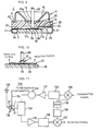
- Fig. 11 shows an electric-circuit block diagram of an RF circuit of a mobile phone 120.
- reference numeral 122 denotes an antenna element
- reference numeral 123 denotes a duplexer
- reference numeral 125 denotes a selector switch
- reference numeral 131 denotes a transmission-side isolator
- reference numeral 132 denotes a transmission-side amplifier
- reference numeral 133 denotes transmission-side interstage band pass filter
- reference numeral 134 denotes a transmission-side mixer
- reference numeral 135 denotes a reception-side amplifier
- reference numeral 136 denotes a reception-side interstage band pass filter
- reference numeral 137 denotes a reception-side mixer
- reference numeral 138 denotes a voltage-controlled oscillator (VCO)
- reference numeral 139 denotes a local band pass filter.
- VCO voltage-controlled oscillator
- the coaxial connector 1 in accordance with the first embodiment can be used as the selector switch 125.
- the coaxial connector 1 in accordance with the first embodiment can be used as the selector switch 125.
- a measurement probe the counterpart coaxial connector
- a signal path from the RF circuit to the antenna element 122 can be switched to a signal path from the RF circuit to the measuring apparatus.
- the measurement probe 126 is removed from the coaxial connector 1
- the signal path from the RF circuit to the measuring apparatus is again switched to the signal path from the RF circuit to the antenna element 122.
- the mobile phone 120 can obtain high reliability.
- the movable terminal, the coaxial connector, and the communications apparatus in accordance with the present invention are not restricted to the above embodiments. Various modifications and changes can be made without departing from the scope of the invention as defined in the claims.
- the coaxial connector is formed by separately producing terminals and insulating cases to combine both of them.
- the coaxial connector may be formed by integrally insert-molding the terminals in the insulating cases.
- the outline of the insulating cases and the configuration of the cavity may be arbitrarily selected according to specifications. For example, they may have rectangular or round forms.
- terminals used in the invention are not restricted to surface-mounted type terminals.
- the terminals of insert-mounted type may be used.
- these components may be connected to each other by wielding.
- the movable terminal includes the frame-shaped portion.
- the two arms of the frame-shaped portion are bent and the spring movable portion is curved in a circular form.
- the plastic deformation of the movable terminal hardly occurs, and the springing property of the movable terminal is not deteriorated.
- the coaxial connector and the communications apparatus having high reliability can be obtained.
Landscapes
- Coupling Device And Connection With Printed Circuit (AREA)
- Multi-Conductor Connections (AREA)
Abstract
Description
- The present invention relates to movable terminals, coaxial connectors, and communications apparatuses incorporating the same.
- Below, it is to be understood that the expression "spring" used in references to "springing properties", "spring movable functions", "spring supporting portions", and the like, does not refer limitatively to a mechanical spring but denotes, more generally, items having "springiness", "elasticity" or "resilience".
- Conventionally, there are mobile communications apparatuses such as mobile phones, which incorporate surface-mounted-type coaxial connectors having signal-path switching functions. In such a coaxial connector, usually, a resin case, a fixed terminal, and a movable terminal having springing property are integrally insert-molded.
- As shown in Fig. 12, a conventional
movable terminal 155 includes a movablemechanical portion 151 having a spring movable function and alead portion 152 bent in a U-shape connected to the movablemechanical portion 151. The movablemechanical portion 151 includes anarm 151a extending to right-and-left sides from thelead portion 152, two spring supporting portions 151b formed at the ends of thearm 151a, a springmovable portion 151c extending substantially parallel to thearms 151a in such a manner that theportion 151c straddles the spring supporting portions 151b, and acontact portion 151d protruding from the springmovable portion 151c. Both ends of the springmovable portion 151c are supported and fixed by the spring supporting portions 151b. The central part of the springmovable portion 151c is curved in a circular form so as to extend upwardly. With the force exerted by the springing property of the circular-formed springy mechanism, thecontact portion 151d abuts with the lower surface of acontact part 141 of afixed terminal 140, and thereby thefixed terminal 140 makes contact with themovable terminal 155 to be connected to each other. - However, the conventional
movable terminal 155 has only onearm 151a and only two bent parts A and B. As a result, when the conventionalmovable terminal 155 is repeatedly pressed into contact with the central contact of the counterpart coaxial connector, plastic deformation of themovable terminal 155 occurs, thereby deteriorating the springing property. That is, after removing the counterpart coaxial connector, thefixed terminal 140 and themovable terminal 155 cannot be contacted and connected in a stable manner. In some cases, bothterminals - Accordingly, it is an object of the present invention to provide a movable terminal, a coaxial connector, which are durable and have good contact/connection reliability, and a communications apparatus incorporating the same.
- In order to accomplish the above object, the present invention provides a movable terminal including a frame-shaped portion, a resilient movable portion having both ends supported by the frame-shaped portion and having a displaceable resilient central part, and a contact portion integrally formed with the resilient movable portion and adapted to make contact with a fixed terminal so that the contact portion is connected to the fixed terminal, in which two arms arranged in parallel to the resilient movable portion of the frame-shaped portion are bent such that the resilient movable portion is curved in a circular, or convexly-curved, shape.
- Preferably, the contact portion is formed on the top of the resilient movable portion curved in the circular shape.
- The present invention further provides a coaxial connector including an insulating case having a cavity in which the central contact of a counterpart coaxial connector is inserted, the movable terminal disposed in the cavity of the insulating case such that the movable terminal protrudes in a direction substantially perpendicular to a direction in which the central contact is inserted, a fixed terminal disposed in the cavity of the insulating case to make contact with a contact portion of the movable terminal so that the fixed terminal is connected to the contact portion, and an external terminal disposed on the outside of the insulating case to be electrically connected to an external conductor of the counterpart coaxial connector, in which the contact portion of the movable terminal and the fixed terminal separate from each other and make contact to be connected to each other in accordance with the installation and removal of the counterpart coaxial connector.
- Since the frame-shaped portion has a high mechanical strength, the plastic deformation of the movable terminal hardly occurs even though the movable terminal is repeatedly pressed into contact with the central contact of the counterpart coaxial connector. As a result, the deterioration of springing property (elasticity) can be prevented. Moreover, the resilient movable portion is curved in the circular form by bending a flat plate instead of curving by plastic deformation. Thus, plastic deformation is more unlikely to occur.
- In addition, the present invention provides a communications apparatus incorporating the above coaxial connector, thereby having high reliability.
- Further features and advantages of the present invention will become apparent from the following description of preferred embodiments thereof, given by way of example, and illustrated by the annexed drawings, in which:
- Fig. 1 is an exploded perspective view showing an embodiment of a coaxial connector according to the present invention;
- Fig. 2 is an enlarged perspective view of a movable terminal shown in Fig. 1;
- Fig. 3 is a front view of the movable terminal shown in Fig. 2;
- Fig. 4 is a right side-surface view of the movable terminal shown in Fig. 2;
- Fig. 5 is a left side-surface view of the movable terminal shown in Fig. 2;
- Fig. 6 is a perspective view showing the appearance of the coaxial connector shown in Fig. 1;
- Fig. 7 is a sectional view of the coaxial connector shown in Fig. 6;
- Fig. 8 is a schematic sectional view for illustrating the spring function (elasticity) of a resilient movable portion of the movable terminal;
- Fig. 9 is a sectional view obtained when a counterpart coaxial connector is fitted in the coaxial connector shown in Fig. 6;
- Fig. 10 is a schematic sectional view for illustrating the spring function (elasticity) of the resilient movable portion of the movable terminal in the above situation;
- Fig. 11 is a block diagram of an embodiment of a communication apparatus according to the present invention; and
- Fig. 12 is a perspective view showing a conventional movable terminal and a conventional fixed terminal.
-
- With reference to the attached drawings, a description will be given of a movable terminal, a coaxial connector, and a communications apparatus according to embodiments of the present invention.
- Fig. 1 is an exploded perspective view showing the structure of a coaxial connector according to an embodiment of the present invention. A coaxial connector (coaxial receptacle) 1 is composed of a synthetic resin insulating case split into a lower
insulating case 2A and an upperinsulating case 2B, a metalfixed terminal 21, a metalmovable terminal 31, and a metal external terminal (an external conductor) 41. - The lower
insulating case 2A has substantially a rectangular shape. At each of the two comers of one side of the upper surface (a split surface) of the lowerinsulating case 2A, a guide protrusion 3 for positioning the upperinsulating case 2B is disposed. Near each of the guide protrusions 3, and on the opposite side of the lowerinsulating case 2A , cavity-like leg-receiving portions 4 for fitting the legs (not shown) of the upperinsulating case 2B are provided. In addition, rectangular cut-awayportions 6 and 7 are formed at the central parts of the mutually opposing edges of the lowerinsulating case 2A. The cut-away portion 6 contains a lead portion 24 (which will be described below) of thefixed terminal 21. The cut-away portion 7 contains a lead portion 34 (which will be described below) of themovable terminal 31. The dimensions of the cut-awayportions 6 and 7 are set such that there is formed a clearance sufficient for preventing capillary effect due to the flux of solder used for mounting between the lowerinsulating case 2A and thelead portion 24 of theterminal 21 and thelead portion 34 of theterminal 31. - The upper
insulating case 2B is substantially rectangular. Anentrance hole 13 having a round cross section is formed in the center of the upper insulatingcase 2B. Theentrance hole 13 penetrates the upperinsulating case 2B. The central contact of a counterpart coaxial connector is supposed to be inserted into theentrance hole 13. - In addition, four round legs are disposed on the bottom surface (the other split surface) of the upper insulating
case 2B. These legs are not shown in the figure. A groove 15 (see Fig. 7) having a V-shaped cross section is formed between theentrance hole 13 and an edge on which thefixed terminal 21 is led out. Thegroove 15 extends in a direction substantially perpendicular to the direction in which thefixed terminal 21 is led out. - Even though there is clearance arranged between the lower
insulating case 2A and thelead portion 24 of theterminal 21 and thelead portion 34 of theterminal 31, when solder used for mounting is excessively applied, thereby exceeding a prescribed amount, a solder flux enters from spaces between theinsulating cases terminals groove 15 crossing with thefixed terminal 21 is disposed on the split surface of the upper insulatingcase 2B. With thisgroove 15, there is provided clearance for preventing capillary effect occurring between theinsulating cases fixed terminal 21. As a result, the flux cannot enter. - The
fixed terminal 21 is typically formed by punching and bending a metal plate such as a flat stainless steel plate. The fixedterminal 21 is composed of acontact portion 22 with which themovable terminal 31 comes into contact, a fixedportion 23 sandwiched by the insulatingcases lead portion 24 bent in an L-shape. Both sides of thecontact portion 22 are folded at predetermined angles to form a horizontal face 22a andinclined faces 22b on each side of the horizontal face 22a. - At the sides of the fixed
portion 23 are formed around hole 26a and an oval hole 26b. The legs of the upper insulatingcase 2B are fitted into theholes 26a and 26b, and the fixedterminal 21 is attached with the upper insulatingcase 2B with good positional accuracy with reference to theround hole 26a. The hole 26b has an oval shape in order to allow for production margin errors. The fixedterminal 21 is attached such that the horizontal face 22a of thecontact portion 22 and the fixedportion 23 are in close contact with the bottom of the upper insulatingcase 2B. In addition, a clearance is provided at a part where the fixedterminal 21 crosses with thegroove 15. - The
lead portion 24 is downwardly extended substantially in parallel to a side surface of the lower insulatingcase 2A. The top end of thelead portion 24 is inwardly bent at an angle of substantially 90 degrees so that the top portion is flush with the bottom surface of the lower insulatingcase 2A. Thelead portion 24 serves as a soldered part. - The
movable terminal 31 is typically formed by punching and bending a metal plate such as a stainless steel plate having springing property in a predetermined shape. As shown in Figs. 2 to 5, themovable terminal 31 is composed of amovable contact portion 32 having a spring movable function and serves as a contact point with the fixedterminal 21, a fixedportion 33 attached in the insulatingcases lead portion 34 bent in an L-shape. Themovable contact portion 32 includes a frame-shapedportion 37, a spring movable (resilient)portion 38 whose both ends are supported by the frame-shapedportion 37, and acontact portion 39 disposed at the center of the springmovable portion 38. - The structure of the substantially rectangular frame-shaped
portion 37 has a high mechanical strength, and plastic deformation thereby hardly occurs. Specifically, the frame-shapedportion 37 is composed of twospring supporting portions 37b connecting to the springmovable portion 38 and extending in a direction substantially perpendicular to the springmovable portion 38, and twoarms 37a arranged substantially parallel to the springmovable portion 38. The springmovable portion 38 curves such that theportion 38 bulges upwardly in a circular shape, and has a desirable height at the top thereof. Thecontact portion 39 is provided on the top of the springmovable portion 38 curved in the circular shape. - The curve of the spring
movable portion 38 is formed by folding the twoarms 37a at four positions A, B, C, and D so that the centers of the twoarms 37a downwardly bulge. Thus, the springmovable portion 38 maintains the curve obtained by bending a flat plate without using a curve due to plastic deformation. As a result, when the counterpart coaxial connector is installed and displaced, the springmovable portion 38 only reverses to be back to an initial flat configuration. Therefore, even though attachment and detachment of the counterpart coaxial connector are repeated, the plastic deformation of the springmovable portion 38 is more unlikely to occur. - At the sides of the fixed
portion 33 are formed around hole 36a and anoval hole 36b. Into theholes case 2B, and themovable terminal 31 is attached to the upper insulatingcase 2B with accurate position. In this case, themovable terminal 31 is attached in a state in which the fixedportion 33 is closely attached to the bottom of the upper insulatingcase 2B. - The
lead portion 34 is downwardly extended substantially in parallel to a side of the lower insulatingcase 2A. The top end of thelead portion 34 is inwardly bent at an angle of substantially 90 degrees so that the top end thereof is flush with the bottom of the lower insulatingcase 2A to be used as a soldered part. - The
external terminal 41 in contact with the external conductor of the counterpart coaxial connector is typically formed by punching, bending, and drawing a plate of metal such as brass and spring phosphor bronze. Aflat portion 42 of the center of the plate is disposed over the upper surface of the upper insulatingcase 2B. Aleg 43 is disposed at each of the four corners of theflat portion 42. Thelegs 43 are folded along the side surfaces and bottom surface of an assembly composed of theterminals cases top end portions 43a of thelegs 43 are arranged so that theportions 43a are substantially flush with the bottom of the lower insulatingcase 2A, and are used as soldered parts. - At the center of the
flat portion 42, a through-hole cavity 45 is formed in such a manner that the through-hole cavity 45 is concentric with theround entrance hole 13 of the upper insulatingcase 2B. The through-hole cavity 45 has a conical opening, and around hole 45a is formed at the center thereof. The external conductor of the counterpart coaxial connector is fitted into the through-hole cavity 45. Theexternal terminal 41 is usually used as a ground. The external surface of theexternal terminal 41 is plated when necessary. - Fig. 6 shows a perspective view of the appearance of a
coaxial connector 1 assembled in the above manner. Fig. 7 shows a sectional view thereof. As shown in Fig. 7, in thecoaxial connector 1, since the top end portions of theterminals case 2A, they thereby form a surface-mountable structure. In addition, the through-hole cavity 45 is formed in theexternal terminal 41, a stable and reliable connection is achieved with the counterpart coaxial connector. - The fixed
terminal 21 and themovable terminal 31 are arranged in such a manner that the fixedterminal 21 is disposed above themovable terminal 31 in the inside space of an insulating-case structure composed of the insulatingcases movable contact portion 32 of themovable terminal 31 is arranged substantially horizontally in the inside space of the insulating-case structure. That is, themovable contact portion 32 is arranged in a direction substantially perpendicular to a direction in which the central contact of the counterpart coaxial connector is inserted. - Next, the function of the
coaxial connector 1 will be illustrated with reference to Figs. 7 to 10. - As shown in Figs. 7 and 8, when the counterpart coaxial connector is not attached, the central part of the spring
movable portion 38 curves upwardly. In this state, themovable terminal 31 is in contact with the fixedterminal 21 by the urging force due to the springing property of the springmovable portion 38, and bothterminals - In contrast, as shown in Figs. 9 and 10, when the counterpart coaxial connector is attached, the central part of the spring
movable portion 38 is pressed down to be reversed by thecentral contact 65 of the counterpart coaxial connector inserted from theupper entrance hole 13, and the central part thereof extends downwardly in a circular form. In this situation, thecontact portion 39 of themovable terminal 31 separates from thecontact portion 22 of the fixedterminal 21 and thereby the fixedterminal 21 and themovable terminal 31 are electrically disconnected, while thecentral contact 65 and themovable terminal 31 are electrically connected. At the same time, the external conductor (not shown) of the counterpart coaxial connector is fitted into theexternal terminal 41 to be electrically connected to each other. - In the above situation, a reactive force occurs on both ends of the spring movable portion 38 (see Fig. 10). The reactive force is supported by the
frame portion 37, particularly, by the folded parts A, B, C, and D formed on the twoarms 37a. That is, as compared with the conventional movable terminal having only two folded parts shown in Fig. 12, themovable terminal 31 of the first embodiment has the four folded parts A, B, C, and D. As a result, the share load of the reactive force applied to each of the folded parts can be reduced. Thus, even though themovable terminal 31 is repeatedly pressed in contact with thecentral contact 65 of the counterpart coaxial connector and such a contact is continuously repeated for a long time, the plastic deformation of themovable terminal 31 hardly occurs and thereby the springing property of themovable terminal 31 is not deteriorated. - Furthermore, even if an excessive force is applied to the spring
movable portion 38 when the counterpart coaxial connector is attached, since the lowest part of the springmovable portion 38 comes in contact with the upper surface of the lower insulatingcase 2A, the displacement of the springmovable portion 38 does not exceed a prescribed amount. - When the counterpart coaxial connector is removed from the
coaxial connector 1, the central part of the springmovable portion 38 returns to an upwardly bulged state by using the springing property. In this state, the fixedterminal 21 and themovable terminal 31 are electrically connected to each other, while thecentral contact 65 and themovable terminal 31 are electrically disconnected from each other. - A description will be given of a communications apparatus according to a second embodiment of the present invention by using an example of a mobile phone.
- Fig. 11 shows an electric-circuit block diagram of an RF circuit of a
mobile phone 120. In Fig. 11,reference numeral 122 denotes an antenna element,reference numeral 123 denotes a duplexer,reference numeral 125 denotes a selector switch,reference numeral 131 denotes a transmission-side isolator,reference numeral 132 denotes a transmission-side amplifier,reference numeral 133 denotes transmission-side interstage band pass filter,reference numeral 134 denotes a transmission-side mixer,reference numeral 135 denotes a reception-side amplifier,reference numeral 136 denotes a reception-side interstage band pass filter,reference numeral 137 denotes a reception-side mixer,reference numeral 138 denotes a voltage-controlled oscillator (VCO), andreference numeral 139 denotes a local band pass filter. - In this case, as the
selector switch 125, thecoaxial connector 1 in accordance with the first embodiment can be used. With this arrangement, for example, when the electrical characteristics of the RF circuit are checked in a process for manufacturing themobile phone 120, by fitting a measurement probe (the counterpart coaxial connector) 126 connected to a measuring apparatus into thecoaxial connector 1, a signal path from the RF circuit to theantenna element 122 can be switched to a signal path from the RF circuit to the measuring apparatus. When themeasurement probe 126 is removed from thecoaxial connector 1, the signal path from the RF circuit to the measuring apparatus is again switched to the signal path from the RF circuit to theantenna element 122. With the installation of thecoaxial connector 1, themobile phone 120 can obtain high reliability. - The movable terminal, the coaxial connector, and the communications apparatus in accordance with the present invention are not restricted to the above embodiments. Various modifications and changes can be made without departing from the scope of the invention as defined in the claims.
- In the above embodiments, the coaxial connector is formed by separately producing terminals and insulating cases to combine both of them. However, the coaxial connector may be formed by integrally insert-molding the terminals in the insulating cases. In addition, the outline of the insulating cases and the configuration of the cavity may be arbitrarily selected according to specifications. For example, they may have rectangular or round forms.
- Furthermore, terminals used in the invention are not restricted to surface-mounted type terminals. The terminals of insert-mounted type may be used. In addition, after separately producing the movable contact portion of the movable terminal, the fixed portion, and the lead portion, these components may be connected to each other by wielding.
- As described above, in the present invention, the movable terminal includes the frame-shaped portion. The two arms of the frame-shaped portion are bent and the spring movable portion is curved in a circular form. As a result, the plastic deformation of the movable terminal hardly occurs, and the springing property of the movable terminal is not deteriorated. Thus, the coaxial connector and the communications apparatus having high reliability can be obtained.
Claims (4)
- A movable terminal (31) comprising:a frame-shaped portion (37);a resilient movable portion (38) having both ends supported by the frame-shaped portion (37) and having a displaceable resilient central part; anda contact portion (39) integrally provided with the resilient movable portion (38) and adapted to make contact with a fixed terminal so that the contact portion is connected to the fixed terminal;wherein two arms (37a) of the frame-shaped portion (37), arranged substantially parallel to the resilient movable portion (38), are bent such that the resilient movable portion (38) is curved in a circular form.
- A movable terminal (31) according to Claim 1, wherein the contact portion (39) is formed on the top of the resilient movable portion (38) curved in the circular form.
- A coaxial connector (1) comprising:an insulating case (2A,2B) having a cavity in which the central contact of a counterpart coaxial connector is inserted;the movable terminal (31) according to one of Claims 1 and 2, disposed in the cavity of the insulating case such that the movable terminal (31) protrudes in a direction substantially perpendicular to a direction in which the central contact is inserted;a fixed terminal (21) disposed in the cavity of the insulating case to make contact with the contact portion (39) of the movable terminal (31) so that the fixed terminal (21) is connected to the contact portion (39); andan external terminal (41) disposed on the outside of the insulating case to be electrically connected to an external conductor of the counterpart coaxial connector;wherein the contact portion (39) of the movable terminal (31) and the fixed terminal (21) separate from each other and make contact to be connected to each other in accordance with the installation and removal of the counterpart coaxial connector.
- A communications apparatus incorporating the coaxial connector (1) according to Claim 3.
Applications Claiming Priority (2)
| Application Number | Priority Date | Filing Date | Title |
|---|---|---|---|
| JP2000001916A JP3473531B2 (en) | 2000-01-07 | 2000-01-07 | Coaxial connector and communication device |
| JP2000001916 | 2000-01-07 |
Publications (2)
| Publication Number | Publication Date |
|---|---|
| EP1115183A1 true EP1115183A1 (en) | 2001-07-11 |
| EP1115183B1 EP1115183B1 (en) | 2007-03-07 |
Family
ID=18531091
Family Applications (1)
| Application Number | Title | Priority Date | Filing Date |
|---|---|---|---|
| EP01400033A Expired - Lifetime EP1115183B1 (en) | 2000-01-07 | 2001-01-08 | Movable terminal, coaxial connector, and communications apparatus incorporating the same |
Country Status (6)
| Country | Link |
|---|---|
| US (1) | US6751317B2 (en) |
| EP (1) | EP1115183B1 (en) |
| JP (1) | JP3473531B2 (en) |
| KR (1) | KR100394350B1 (en) |
| CN (1) | CN1188937C (en) |
| DE (1) | DE60127003T2 (en) |
Cited By (6)
| Publication number | Priority date | Publication date | Assignee | Title |
|---|---|---|---|---|
| EP1174958A3 (en) * | 2000-07-21 | 2002-06-26 | Murata Manufacturing Co., Ltd. | Coaxial connector and communication device having the same |
| WO2003058766A1 (en) * | 2001-12-28 | 2003-07-17 | Matsushita Electric Works, Ltd. | Connector with switching function |
| EP1381120A1 (en) * | 2002-07-11 | 2004-01-14 | Itt Manufacturing Enterprises, Inc. | PCB-mounted switch |
| EP1304770A3 (en) * | 2001-10-18 | 2004-02-04 | Hirose Electric Co., Ltd. | Coaxial connector with a switch |
| WO2009157220A1 (en) | 2008-06-25 | 2009-12-30 | 株式会社村田製作所 | Coaxial connector |
| CN103117470A (en) * | 2013-03-21 | 2013-05-22 | 昆山嘉华电子有限公司 | Coaxial connector |
Families Citing this family (30)
| Publication number | Priority date | Publication date | Assignee | Title |
|---|---|---|---|---|
| JP3473560B2 (en) | 2000-07-21 | 2003-12-08 | 株式会社村田製作所 | Coaxial connector and communication device provided with the coaxial connector |
| US6939152B1 (en) * | 2004-07-20 | 2005-09-06 | Su-Lien Chen | Microswitch connector |
| TWM270536U (en) * | 2004-12-10 | 2005-07-11 | Advanced Connectek Inc | Coaxial connector |
| TWD115462S (en) * | 2006-01-06 | 2007-02-11 | 正崴精密工業股份有限公司 | Microphone rubber |
| USD538794S1 (en) * | 2006-01-07 | 2007-03-20 | Cheng Uei Precision Industry Co., Ltd. | Microphone connector |
| USD539790S1 (en) * | 2006-03-02 | 2007-04-03 | Cheng Uei Precision Industry Co., Ltd. | Microphone can shell |
| DE102007051101A1 (en) * | 2007-10-24 | 2009-10-08 | Ims Connector Systems Gmbh | Microswitch for a coaxial connector |
| TWI431875B (en) * | 2009-03-09 | 2014-03-21 | Hon Hai Prec Ind Co Ltd | Electrical connector and terminals |
| JP5370276B2 (en) * | 2009-08-25 | 2013-12-18 | 株式会社村田製作所 | Receptacle for coaxial connector |
| CN202076457U (en) * | 2010-12-20 | 2011-12-14 | 深圳市电连精密技术有限公司 | Improved high frequency signal connector |
| JP5472272B2 (en) * | 2011-12-05 | 2014-04-16 | 株式会社村田製作所 | Coaxial connector plug and manufacturing method thereof |
| CN102820593B (en) * | 2012-04-26 | 2016-04-06 | 番禺得意精密电子工业有限公司 | The positive force supplying method of coaxial connector and a kind of electric connector |
| JP5904283B2 (en) * | 2012-08-24 | 2016-04-13 | 株式会社村田製作所 | Coaxial connector |
| JP5964259B2 (en) * | 2013-02-08 | 2016-08-03 | 株式会社村田製作所 | Coaxial connector |
| CN103337751A (en) * | 2013-06-13 | 2013-10-02 | 连展科技电子(昆山)有限公司 | Micro radio-frequency connector and movable conductive terminal thereof |
| CN103915703B (en) * | 2014-03-05 | 2019-09-20 | 连展科技电子(昆山)有限公司 | Miniature radio-frequency connector |
| USD855590S1 (en) * | 2017-10-27 | 2019-08-06 | Haibo Ql | Home speaker mount |
| CN107887735B (en) * | 2017-11-28 | 2019-12-10 | 昆山嘉华电子有限公司 | Coaxial connector |
| USD875720S1 (en) * | 2018-06-06 | 2020-02-18 | Logitech Europe S.A. | Microphone splitter |
| USD879749S1 (en) * | 2018-11-01 | 2020-03-31 | Shenzhen Zhiyuan Tongtai Technology Co., Ltd. | Home speaker mount |
| USD892773S1 (en) * | 2018-12-27 | 2020-08-11 | Michael Dale McGee | Secure microphone lock clip |
| USD887397S1 (en) * | 2020-02-24 | 2020-06-16 | Qin Wang | Speaker wall mount |
| CN213484020U (en) * | 2020-10-27 | 2021-06-18 | 富士康(昆山)电脑接插件有限公司 | Radio frequency connector |
| USD916687S1 (en) * | 2020-12-23 | 2021-04-20 | Shujuan SHI | Stand for loudspeaker |
| CN112636114B (en) * | 2021-01-03 | 2025-08-29 | 昆山嘉华电子有限公司 | Coaxial connector |
| USD933640S1 (en) * | 2021-03-29 | 2021-10-19 | Guangzhou Xinsheng Innovation Technology Co., Ltd. | USB microphone |
| JP2025164004A (en) * | 2024-04-18 | 2025-10-30 | 株式会社村田製作所 | Coaxial connector with switch and coaxial connector set including said coaxial connector with switch |
| WO2025220729A1 (en) * | 2024-04-18 | 2025-10-23 | 株式会社村田製作所 | Switch-equipped coaxial connector, and coaxial connector set provided with said switch-equipped coaxial connector |
| JP2025164002A (en) * | 2024-04-18 | 2025-10-30 | 株式会社村田製作所 | Coaxial connector with switch and coaxial connector set including said coaxial connector with switch |
| WO2025220726A1 (en) * | 2024-04-18 | 2025-10-23 | 株式会社村田製作所 | Coaxial connector equipped with switch and coaxial connector set comprising coaxial connector equipped with switch |
Citations (2)
| Publication number | Priority date | Publication date | Assignee | Title |
|---|---|---|---|---|
| WO1995030258A1 (en) * | 1994-04-28 | 1995-11-09 | Polaroid Corporation | Electrostatic discharge protection device |
| EP0929128A1 (en) * | 1998-01-13 | 1999-07-14 | Murata Manufacturing Co., Ltd. | Coaxial connector |
Family Cites Families (12)
| Publication number | Priority date | Publication date | Assignee | Title |
|---|---|---|---|---|
| US5281176A (en) | 1991-07-22 | 1994-01-25 | Daido Tokushuko Kabushiki Kaisha | Contact member with composite sintered metal paste strip having 1-5 wt % carbon diffusion bonded therein |
| US5139427A (en) | 1991-09-23 | 1992-08-18 | Amp Incorporated | Planar array connector and flexible contact therefor |
| JP3251801B2 (en) | 1995-03-03 | 2002-01-28 | ヒロセ電機株式会社 | High frequency switch for board mounting |
| US5575690A (en) | 1994-10-28 | 1996-11-19 | Tvm, Inc. | Hybrid modular electrical connector system |
| JPH09147996A (en) * | 1995-11-28 | 1997-06-06 | Smk Corp | Connector with changeover switch |
| FR2743200B1 (en) * | 1995-12-28 | 1998-01-23 | Alcatel Mobile Comm France | SWITCHED CONNECTOR FOR RADIOCOMMUNICATION TERMINAL AND RELATED CONNECTION SOCKET |
| JP3824723B2 (en) | 1996-12-27 | 2006-09-20 | アルプス電気株式会社 | Multi-directional switch |
| JPH10241796A (en) * | 1997-02-26 | 1998-09-11 | Matsushita Electric Works Ltd | Connector |
| JP3539130B2 (en) * | 1997-05-27 | 2004-07-07 | 松下電工株式会社 | Coaxial cable connector |
| JP2889562B1 (en) | 1998-04-21 | 1999-05-10 | エスエムケイ株式会社 | Coaxial connector with switch |
| JP3346360B2 (en) | 1999-12-21 | 2002-11-18 | 株式会社村田製作所 | Electronic components, coaxial connectors and communication equipment |
| JP3446726B2 (en) | 2000-08-11 | 2003-09-16 | 株式会社村田製作所 | Movable terminal, coaxial connector and communication device |
-
2000
- 2000-01-07 JP JP2000001916A patent/JP3473531B2/en not_active Expired - Lifetime
-
2001
- 2001-01-08 US US09/756,630 patent/US6751317B2/en not_active Expired - Fee Related
- 2001-01-08 DE DE60127003T patent/DE60127003T2/en not_active Expired - Lifetime
- 2001-01-08 KR KR10-2001-0000942A patent/KR100394350B1/en not_active Expired - Fee Related
- 2001-01-08 EP EP01400033A patent/EP1115183B1/en not_active Expired - Lifetime
- 2001-01-08 CN CNB011029560A patent/CN1188937C/en not_active Expired - Fee Related
Patent Citations (2)
| Publication number | Priority date | Publication date | Assignee | Title |
|---|---|---|---|---|
| WO1995030258A1 (en) * | 1994-04-28 | 1995-11-09 | Polaroid Corporation | Electrostatic discharge protection device |
| EP0929128A1 (en) * | 1998-01-13 | 1999-07-14 | Murata Manufacturing Co., Ltd. | Coaxial connector |
Cited By (12)
| Publication number | Priority date | Publication date | Assignee | Title |
|---|---|---|---|---|
| EP1174958A3 (en) * | 2000-07-21 | 2002-06-26 | Murata Manufacturing Co., Ltd. | Coaxial connector and communication device having the same |
| US6666699B2 (en) | 2000-07-21 | 2003-12-23 | Murata Manufacturing Co., Ltd. | Coaxial connector and communication device having the same |
| EP1304770A3 (en) * | 2001-10-18 | 2004-02-04 | Hirose Electric Co., Ltd. | Coaxial connector with a switch |
| US6761571B2 (en) | 2001-10-18 | 2004-07-13 | Hirose Electric Co., Ltd. | Coaxial connector with a switch |
| WO2003058766A1 (en) * | 2001-12-28 | 2003-07-17 | Matsushita Electric Works, Ltd. | Connector with switching function |
| EP1381120A1 (en) * | 2002-07-11 | 2004-01-14 | Itt Manufacturing Enterprises, Inc. | PCB-mounted switch |
| GB2390756A (en) * | 2002-07-11 | 2004-01-14 | Itt Mfg Enterprises Inc | PCB-mounted switch of a connector |
| US6881082B2 (en) | 2002-07-11 | 2005-04-19 | Itt Manufacturing Enterprises, Inc. | Connection-switch arrangement |
| WO2009157220A1 (en) | 2008-06-25 | 2009-12-30 | 株式会社村田製作所 | Coaxial connector |
| EP2175531A4 (en) * | 2008-06-25 | 2011-03-16 | Murata Manufacturing Co | COAXIAL CONNECTOR |
| CN103117470A (en) * | 2013-03-21 | 2013-05-22 | 昆山嘉华电子有限公司 | Coaxial connector |
| CN103117470B (en) * | 2013-03-21 | 2015-06-10 | 昆山嘉华电子有限公司 | Coaxial connector |
Also Published As
| Publication number | Publication date |
|---|---|
| DE60127003T2 (en) | 2007-06-21 |
| KR100394350B1 (en) | 2003-08-09 |
| JP3473531B2 (en) | 2003-12-08 |
| CN1188937C (en) | 2005-02-09 |
| JP2001196136A (en) | 2001-07-19 |
| US6751317B2 (en) | 2004-06-15 |
| CN1304193A (en) | 2001-07-18 |
| DE60127003D1 (en) | 2007-04-19 |
| EP1115183B1 (en) | 2007-03-07 |
| US20010050983A1 (en) | 2001-12-13 |
| KR20010070463A (en) | 2001-07-25 |
Similar Documents
| Publication | Publication Date | Title |
|---|---|---|
| EP1115183B1 (en) | Movable terminal, coaxial connector, and communications apparatus incorporating the same | |
| US6783374B2 (en) | Electronic component, coaxial connector, and communication device | |
| US6554630B2 (en) | Movable terminal, coaxial connector, and communication apparatus | |
| KR100491682B1 (en) | Coaxial Connector with Switch | |
| KR101802731B1 (en) | Coaxial connector with switch | |
| US20040229486A1 (en) | Coaxial connector and communication device | |
| JP3473559B2 (en) | Coaxial connector, manufacturing method thereof, and communication device | |
| EP1174960B1 (en) | Coaxial connector and communication device having the same | |
| US6473045B1 (en) | Coaxial connector assembly and antenna assembly having a switching function | |
| JP2004319227A (en) | Coaxial connector with switch | |
| US20060105640A1 (en) | Low profile circuit board connector | |
| JP5587449B1 (en) | Coaxial connector with switch | |
| JP2002093533A (en) | Coaxial connector and communication device | |
| JP2004031087A (en) | Coaxial connector with switch | |
| JP2002075555A (en) | Coaxial connector and communication device | |
| JP4496667B2 (en) | Coaxial connector and communication device | |
| JP4586315B2 (en) | Coaxial connector and communication device | |
| WO2025220729A1 (en) | Switch-equipped coaxial connector, and coaxial connector set provided with said switch-equipped coaxial connector | |
| JP2003203727A (en) | Coaxial connector with switch |
Legal Events
| Date | Code | Title | Description |
|---|---|---|---|
| PUAI | Public reference made under article 153(3) epc to a published international application that has entered the european phase |
Free format text: ORIGINAL CODE: 0009012 |
|
| 17P | Request for examination filed |
Effective date: 20010113 |
|
| AK | Designated contracting states |
Kind code of ref document: A1 Designated state(s): DE FR GB |
|
| AX | Request for extension of the european patent |
Free format text: AL;LT;LV;MK;RO;SI |
|
| AKX | Designation fees paid |
Free format text: DE FR GB |
|
| GRAP | Despatch of communication of intention to grant a patent |
Free format text: ORIGINAL CODE: EPIDOSNIGR1 |
|
| GRAS | Grant fee paid |
Free format text: ORIGINAL CODE: EPIDOSNIGR3 |
|
| GRAA | (expected) grant |
Free format text: ORIGINAL CODE: 0009210 |
|
| AK | Designated contracting states |
Kind code of ref document: B1 Designated state(s): DE FR GB |
|
| REG | Reference to a national code |
Ref country code: GB Ref legal event code: FG4D |
|
| REF | Corresponds to: |
Ref document number: 60127003 Country of ref document: DE Date of ref document: 20070419 Kind code of ref document: P |
|
| ET | Fr: translation filed | ||
| RAP2 | Party data changed (patent owner data changed or rights of a patent transferred) |
Owner name: MURATA MANUFACTURING CO., LTD. |
|
| PLBE | No opposition filed within time limit |
Free format text: ORIGINAL CODE: 0009261 |
|
| STAA | Information on the status of an ep patent application or granted ep patent |
Free format text: STATUS: NO OPPOSITION FILED WITHIN TIME LIMIT |
|
| 26N | No opposition filed |
Effective date: 20071210 |
|
| PGFP | Annual fee paid to national office [announced via postgrant information from national office to epo] |
Ref country code: FR Payment date: 20120202 Year of fee payment: 12 |
|
| PGFP | Annual fee paid to national office [announced via postgrant information from national office to epo] |
Ref country code: DE Payment date: 20120104 Year of fee payment: 12 |
|
| PGFP | Annual fee paid to national office [announced via postgrant information from national office to epo] |
Ref country code: GB Payment date: 20120104 Year of fee payment: 12 |
|
| GBPC | Gb: european patent ceased through non-payment of renewal fee |
Effective date: 20130108 |
|
| REG | Reference to a national code |
Ref country code: FR Ref legal event code: ST Effective date: 20130930 |
|
| PG25 | Lapsed in a contracting state [announced via postgrant information from national office to epo] |
Ref country code: DE Free format text: LAPSE BECAUSE OF NON-PAYMENT OF DUE FEES Effective date: 20130801 |
|
| REG | Reference to a national code |
Ref country code: DE Ref legal event code: R119 Ref document number: 60127003 Country of ref document: DE Effective date: 20130801 |
|
| PG25 | Lapsed in a contracting state [announced via postgrant information from national office to epo] |
Ref country code: FR Free format text: LAPSE BECAUSE OF NON-PAYMENT OF DUE FEES Effective date: 20130131 Ref country code: GB Free format text: LAPSE BECAUSE OF NON-PAYMENT OF DUE FEES Effective date: 20130108 |