EP1115181A1 - Electrical connector - Google Patents
Electrical connector Download PDFInfo
- Publication number
- EP1115181A1 EP1115181A1 EP00310656A EP00310656A EP1115181A1 EP 1115181 A1 EP1115181 A1 EP 1115181A1 EP 00310656 A EP00310656 A EP 00310656A EP 00310656 A EP00310656 A EP 00310656A EP 1115181 A1 EP1115181 A1 EP 1115181A1
- Authority
- EP
- European Patent Office
- Prior art keywords
- short
- detecting
- circuit
- housings
- detecting member
- Prior art date
- Legal status (The legal status is an assumption and is not a legal conclusion. Google has not performed a legal analysis and makes no representation as to the accuracy of the status listed.)
- Withdrawn
Links
- 238000005452 bending Methods 0.000 claims description 2
- 229910000859 α-Fe Inorganic materials 0.000 description 3
- 238000003780 insertion Methods 0.000 description 1
- 230000037431 insertion Effects 0.000 description 1
- 239000002184 metal Substances 0.000 description 1
- 238000000034 method Methods 0.000 description 1
- 230000000717 retained effect Effects 0.000 description 1
Images





Classifications
-
- H—ELECTRICITY
- H01—ELECTRIC ELEMENTS
- H01R—ELECTRICALLY-CONDUCTIVE CONNECTIONS; STRUCTURAL ASSOCIATIONS OF A PLURALITY OF MUTUALLY-INSULATED ELECTRICAL CONNECTING ELEMENTS; COUPLING DEVICES; CURRENT COLLECTORS
- H01R13/00—Details of coupling devices of the kinds covered by groups H01R12/70 or H01R24/00 - H01R33/00
- H01R13/62—Means for facilitating engagement or disengagement of coupling parts or for holding them in engagement
- H01R13/639—Additional means for holding or locking coupling parts together, after engagement, e.g. separate keylock, retainer strap
-
- H—ELECTRICITY
- H01—ELECTRIC ELEMENTS
- H01R—ELECTRICALLY-CONDUCTIVE CONNECTIONS; STRUCTURAL ASSOCIATIONS OF A PLURALITY OF MUTUALLY-INSULATED ELECTRICAL CONNECTING ELEMENTS; COUPLING DEVICES; CURRENT COLLECTORS
- H01R2201/00—Connectors or connections adapted for particular applications
- H01R2201/26—Connectors or connections adapted for particular applications for vehicles
Definitions
- the present invention relates to an electrical connector.
- JP 11-149958 describes a connector provided with a function for detecting the fitted state of connector housings and capable of releasing a short-circuiting state of terminal fittings of a first connector housing by means of a short-circuit releasing member provided on a second connector housing.
- terminal fittings 103 of the first housing 101 are short-circuited by shorting terminals 104, and a fitting detecting member 105 and a short-circuit releasing member 106 are attached to the second housing 102 in a temporarily retained state.
- the two housings 101 and 102 are first fitted together.
- the short-circuit releasing member 106 is pushed in towards a return spring 107, thereby releasing the short-circuiting state.
- the fitting detecting member 105 is pushed in.
- Pushing in the fitting detecting member 105 causes a retaining member 105A thereof to engage with a retaining member 106A of a short-circuit releasing member 106, this short-circuit member 106 being locked in a state whereby it is pressed against the return spring 107.
- the return spring 107 is not shown in Figure 16 for reasons of clarity.
- a locking member (not shown) is bent to a wrong position and interferes with the fitting detecting member 105, preventing the fitting detecting member 105 from being pushed in.
- the half-fitted state can be detected.
- the return spring 107 pushes the short-circuit releasing member 106 out to a temporary retaining position, and the terminal fittings 103 return to their short-circuiting state.
- the fitting detecting means 105 When the two housings 101 and 102 are to be released from their fitted state, the fitting detecting means 105 is moved from a detecting position to a waiting position. This causes the engagement of the retaining members 105A and 106A to be released, the return spring 107 moves the short-circuit releasing member 106 from a short-circuit releasing position to a position allowing short-circuiting to occur, and the terminal fittings 103 are short-circuited.
- the return spring 107 is the means to return the short-circuit releasing member 106 to the position allowing short-circuiting to occur.
- This return spring 107 is provided as a component separate from the short-circuit releasing member 106. Consequently, there is a problem that the number of components is large.
- an electrical connector comprising two housings adapted for mutual fitting and having a resilient latch movable to a locking position to retain said housings in a fitted condition, and movable to non-locking position during movement of said housings through a half-fitted condition
- the connector including a detecting member provided on one of said housings and movable from a retracted to an advanced position, the latch preventing movement of the detecting member when in the non-locking position, and permitting movement of the detecting member when in the locking position
- the connector further including a short-circuit releasing member adapted to cause or release a short-circuit condition between terminals of the other of said housings, wherein said short-circuit releasing member is engageable by said detecting member on movement from the retracted to the advanced condition, to move from a short-circuiting condition to a state in which the short-circuit condition is released.
- the short-circuit releasing member includes a resilient arm which deflects during movement of the detecting member from
- the short-circuit releasing member is preferably 'U' shaped, having two such resilient arms, and insertable in one of said housings in the direction of the engagement axis of the housings.
- a projection of this 'U' shaped member is preferably engageable in a corresponding aperture of the associated housing to prevent lateral movement thereof.
- the arms of the 'U' shaped member are preferably deflectable apart to release the short-circuit condition, the tips of the arms preferably having a ramp surface for engagement with a short-circuit member and for moving the short-circuit member from a short-circuiting to a non-short circuiting condition.
- a connector of the present embodiment is provided with a male housing 10 and a female housing 20, these two housings 10 and 20 being capable of fitting mutually together and of being separated.
- the male housing 10 is made from plastic. As shown in Figures 13 and 14, this male housing 10 has a recess 11 opening onto its upper face. A left and right pair of upwardly protruding male terminal fittings 12 (the terminal fittings of the present invention) and a shorting terminal 13 are housed within this recess 11.
- the shorting terminal 13 has a pair of resilient contacts 14 capable of making resilient contact with the side with the male terminal fittings 12. When the two housings 10 and 20 are in a separated state, the pair of resilient contacts 14 make contact with the pair of male terminal fittings 12, causing a short-circuiting state therebetween.
- the resilient contacts 14 are bent by a short-circuit releasing member 50 so as to become separated from the male terminal fittings 12, thereby releasing the short-circuiting state of the two male terminal fittings 12.
- the female housing 20 is provided with a left and right pair of female terminal fittings 60 capable of making contact with the male terminal fittings 12, a ferrite core 63, the short-circuit releasing member 50, and a fitting detecting member 40.
- the female housing 20 is made from plastic, and is composed of a main body 21 which is long in an anterior-posterior direction, and a fitting member 22 which extends downwards from an anterior end of the main body 21 and which fits into the recess 11 of the male housing 10.
- a cavity 23 is formed within the main body 21 and the fitting member 22, this cavity 23 having an L-shape when viewed from the side and being open to an upper face of the female housing 20.
- the female terminal fittings 60 Housed within the cavity 23 are the female terminal fittings 60, ends of electric wires 61 that are connected to the female terminal fittings 60, and the ferrite core 63. Further, the open portion of the cavity 23 is covered by a cover 25 that is joined to the female housing 20 by a hinge 24.
- the female terminal fittings 60 have an L-shape when viewed from the side, the posterior ends thereof being crimped to the electric wires 61.
- downwardly protruding box-shaped members 62 of the female terminal fittings 60 fit with the male terminal fittings 12.
- the ferrite core 63 which is for noise reduction, has a left and right pair of attachment holes 64 passing therethrough in an anterior-posterior direction, the electric wire 61 passing through these attachment holes 64.
- a pair of left and right side walls 26 are formed at an anterior end portion of the main body 21 of the female housing 20, and attachment spaces 27 are formed between the anterior end portion of the main body 21 and outer side faces of the side walls 26.
- Approximately the entirety of the upper faces of the attachment spaces 27 formed from the side walls 26 is open, lower faces thereof forming base walls 28 which have portions thereof open.
- a detecting position stopping groove 29 and a waiting position stopping groove 30 are formed in two locations, at the anterior and posterior respectively, of each of left and right inner side faces of the side walls 26. Stopping ribs 42A of the fitting detecting member 40 can fit into the detecting position stopping grooves 29 and the waiting position stopping grooves 30. Detecting member escape holes 31, releasing member escape holes 32 and stopping member escape holes 33 are formed in the base walls 28.
- detecting member escape holes 31 open out along outer side faces of the main body 21 of the female housing 20.
- the releasing member escape holes 23 also open out along the outer side faces of the main body 21 and are located to the anterior of the detecting member escape holes 31.
- the stopping member escape holes 33 open out along the left and right side faces of the side walls 26.
- a locking member 35 extends downwards from each base wall 28.
- Each locking member 35 has a detecting space 14 which allows detecting members 43 to be fitted between the locking members 35 and the outer side faces of the main body 21 with only a small space remaining therebetween. While the male housing 10 is in the process of being fitted with the female housing 20, the locking members 35 make contact with lock receiving members (not shown) of the male housing 10, and are thereby bent inwards. When the two housings 10 and 20 reach a correctly fitted state, the locking members 35 return, as a result of their own resilient returning force, to their original position, leaving the detecting spaces 34 empty.
- the fitting detecting member 40 is composed of a horizontal upper face plate 41, a pair of guiding members 42 that extend downwards from anterior ends of left and right side edges of the upper face plate 41, the detecting members 43 that protrude downwards from posterior ends of the guiding members 42, and a pair of stopping members 44 that protrude downwards from posterior ends of the left and right side edges of the upper face plate 41.
- Inner faces of the guiding members 42 form pressing faces 45 for pressing releasing members 52 (to be explained) of the short-circuit releasing member 50.
- Anterior ends of these pressing faces 45 form guiding inclined faces 46 which are taper shaped when viewed from above.
- the pressing faces 45 join in a unified manner with inner faces of the detecting members 43.
- the stopping ribs 42A are formed on outer faces of the guiding members 42. These stopping ribs 42A maintain the fitting detecting member 40 in a waiting position and a detecting position.
- the fitting detecting member 40 is attached to the female housing 20 with the guiding members 42, the detecting members 43, and the stopping members 44 fitting from above into the attachment spaces 27, and the upper face plate 41 covering an upper face of the cover 25.
- the stopping members 44 bend resiliently inwards, stopping protrusions 44A located at lower ends thereof passing through the stopping member escape holes 33. These stopping protrusions 44A engage with edges of the stopping member escape holes 33, thereby preventing the fitting detecting member 40 from moving upwards relative to the female housing 20.
- the inner and outer faces of the guiding members 42 are adjacent, respectively, to the outer side faces of the main body 21 above the base walls 28 and inner side faces of the side walls 26.
- the fitting member 40 is prevented from moving to the left or right of the female housing 20.
- the stopping ribs 42A fit into the waiting position stopping grooves 30, thereby maintaining the fitting detecting member 40 in the waiting position without its moving to the anterior or posterior.
- the fitting detecting member 40 which is maintained in the waiting position, can be moved horizontally in an anterior direction to the detecting position, the side walls 26 bending resiliently outwards and the stopping ribs 42A make sliding contact with inner faces thereof.
- the stopping ribs 42A then fit with the detecting position stopping grooves 29, thereby maintaining the fitting detecting member 40 in the detecting position without its moving to the anterior or posterior.
- the detecting members 43 pass through the detecting member escape holes 31 and protrude downwards from the base walls 28. These detecting members 43 are located so as to fit into the detecting spaces 34 positioned between the locking members 35 (which are in a free state when viewed from their front faces) and the main body 21. When the fitting detecting member 40 is in the waiting position, the detecting members 43 are located to the posterior of the locking members 35 when viewed from the side (the right side in Figure 7). However, when the fitting detecting member 40 has been moved to the detecting position, the detecting members 43 enter the detecting spaces 34 and overlap with the locking members 35 when viewed from the side.
- the detecting members 43 make contact with posterior ends of the locking members 35, thereby preventing the locking members 35 from entering the detecting spaces 34. Consequently, the fitting detecting member 40 is prevented from entering the detecting position.
- the short-circuit releasing member 50 which has an inverted U-shape when viewed from the anterior, is formed in a unified manner from an attachment member 51 that is long and narrow in a left-right direction, and the pair of releasing members 52 that protrude downwards in a mutually parallel manner from left and right ends of the attachment member 51.
- the releasing members 52 are usually in a position allowing short-circuiting to occur, but are capable of being bent resiliently inwards relative to the attachment member 51 (that is, the releasing members 52 are bent towards one another) to a short-circuit releasing position.
- the releasing members 52 return from the short-circuit releasing position to the position allowing short-circuiting to occur due to their own resilient returning force.
- the short-circuit releasing member 50 may be made from either metal or plastic.
- Pressing protrusions 53 are formed on both outer faces of the releasing members 52. These pressing protrusions 53 are formed at height allowing them to engage with the pressing faces 45 of the fitting detecting member 40.
- Contacting members 54 extend inwards from anterior edges of lower ends of the releasing members 52. These contacting members 54 have guiding inclined faces 55 which are taper shaped when viewed from above. The space between both inner sides of the contacting members 54 is usually (that is, when the releasing members 52 are in the position allowing short-circuiting to occur) greater than the dimensions between outer sides of the pair of resilient contacts 14 of the shorting terminal circuit 13 of the male housing 10.
- the pitch between the contacting members 54 is the same as the pitch between the resilient contacts 14. That is, when the short-circuit releasing member 50 is in the short-circuit releasing position, the contacting members 54 do not make contact with the resilient contacts 14 of the shorting terminal 13 even if the two housings 10 and 20 are correctly fitted together. However, when the short-circuit releasing member 50 is moved resiliently to the short-circuit releasing position when the two housings 10 and 20 are correctly fitted together, the contacting members 54 engage from the sides with the resilient contacts 14 and press these towards the anterior (in a direction away from the male terminal fittings 12) by means of the guiding inclined faces.
- the short-circuit releasing member 50 is attached by fitting an attachment protrusion 56, which extends downwards from an anterior edge of the attachment member 51, into an attachment groove 36 of the female housing 20, and by inserting the two releasing members 52 into the attachment spaces 27.
- the attachment operation of the short-circuit releasing member 50 is performed before the fitting detecting member 40 is attached and before the open portion of the cavity 23 is covered by the cover 25.
- the cover 25 pressed down on the attachment member 51 thereof from above, thereby preventing the fitting detecting member 50 from moving upwards.
- the attachment protrusion 56 fits into the attachment groove 36, thereby preventing the fitting detecting member 50 from moving in an anterior-posterior or left-right direction.
- the releasing members 52 pass through the releasing member escape holes 32 and extend downwards.
- the outer faces of the releasing members 52 are located in approximately the same position as the outer side faces of the main body 21, the pressing protrusions 53 protruding outwards relative to the outer side faces of the main body 21 so as to be located in a position whereby they can make contact with the pressing faces 45.
- the pressing protrusions 53 are iocated in the vicinity of the guiding inclined faces 46 at the anterior ends of the guiding members 42.
- the guiding inclined faces 46 and the pressing faces 45 make contact with the pressing protrusions 53 before the anterior edges of the detecting members 43 of the fitting detecting member 40 reach the posterior edge of the locking member 35, and the releasing members 52 are moved to the short-circuit releasing position.
- the fitting member 22 is fitted into the recess 11 while the fitting detecting member 40 is in a state whereby it has been moved to the waiting position.
- the locking members 35 are bent temporarily inwards from a locking position to a non-locking position.
- the locking members 35 return resiliently to the locking position, thereby locking the two housings 10 and 20 in an inseparable state.
- the releasing members 52 of the short-circuit releasing member 50 are in the position allowing short-circuiting to occur. Consequently, the male terminal fittings 12 of the male housing 10 are short-circuited by the shorting terminal 13.
- the fitting detecting member 40 is slid to the anterior to the detecting position.
- the guiding inclined faces 46 and the pressing faces 45 of the fitting detecting member 40 make contact in turn with the pressing protrusions 53.
- the releasing members 52 are pressed resiliently into the short-circuit releasing position.
- the guiding inclined faces 53 of the contacting members 54 of the releasing members 52 make contact from the sides with the resilient contacts 14 of the shorting terminal 13.
- These guiding inclined faces 55 press against the resilient contacts 14, causing them to bend away from the male terminal fittings 12.
- the resilient returning force of the resilient contacts 14 exerts a pushing force in a posterior direction on the contacting members 54 of the short-circuit releasing member 50.
- the releasing members 52 and the contacting members 54 are located so as to make contact with the anterior end face of the main body 21 of the female housing 20. Consequently, the releasing member 52 and the contacting members 54 are prevented from moving to the posterior, and the resilient contacts 14 are reliably maintained in a position whereby they do not make contact with the male terminal fittings 12.
- the short-circuit releasing operation of the short-circuit releasing member 50 is completed before the fitting detecting member 40 reaches the detecting position.
- the insertion begins of the detecting members 43 of the fitting detecting member 40 into the detecting spaces 34 between the locking members 35 and the main body 21.
- the stopping ribs 42A fit with a click into the detecting position stopping grooves 29 located at the anterior. This click informs the operator that the fitting detecting member 40 has reached the detecting position and, simultaneously, the fact of the fitting detecting member 40 reaching the detecting position informs the operator that the two housings 10 and 20 are correctly fitted together. In this manner, the fitting operation of the two housings 10 and 20, the short-circuit releasing operation of the male terminal fittings 12, and the fitting detecting operation of the two housings 10 and 20 are all completed.
- the locking members 35 are in the non-locking position within the detecting spaces 34.
- the detecting members 43 strike against posterior ends of the locking members 35 which are in the non-locking position, thereby preventing the fitting detecting member 40 from moving further towards the anterior.
- the fact that the fitting detecting member 40 has moved less than the correct distance will inform the operator that the two housings 10 and 20 are in a half-fitted state.
- the click that accompanies the stopping ribs 42A fitting into the anterior located detecting position stopping grooves 29 will not be heard, thereby allowing the half-fitted state to be detected.
- the fitting detecting member 40 When the two housings 10 and 20, which have been fitted together correctly, are to be separated, the fitting detecting member 40 is first slid towards the posterior from the detecting position to the waiting position. Simultaneously, the pressing faces 45 and the guiding inclined faces 46 of the fitting detecting member 40 are separated, in turn, from the pressing protrusions 53. As a result, the releasing members 52, due to their own resilient returning force, move resiliently outwards from the short-circuit releasing position to the position allowing short-circuiting to occur. As the releasing members 52 return to their original position, the contacting members 54 are released, in an outwards direction, from the resilient contacts 14. The resilient contacts 14 move towards the posterior due to their own resilient returning force and make contact with the male terminal fittings 12. Consequently, the male terminal fittings 12 are again in the short-circuiting state.
- the releasing members 52 of the short-circuit releasing member 50 move as a result of their resilient returning force from the short-circuiting releasing position to the position allowing short-circuiting to occur. Consequently, a separate means for moving the releasing members 52 to the position allowing short-circuiting to occur is not required. By this means, the number of components is reduced. Furthermore, when the two housings 10 and 20 have been fitted together, the releasing members 52 are pushed from the position allowing short-circuiting to occur to the short-circuit releasing position as the fitting detecting member 40 is moved from the waiting position to the detecting position. Consequently, both the detecting operation of the fitting detecting member 40 and the short-circuit releasing operation are performed with a single action. By this means, operability is improved.
Landscapes
- Details Of Connecting Devices For Male And Female Coupling (AREA)
Abstract
The invention provides an electrical connector with a reduced number of components
and improved operability. As a fitting detecting member 40 is moved from a detecting
position to a waiting position, releasing members 52 of a short-circuit releasing member
50 return, due to their own resilient returning force, from a short-circuit releasing
position to a position allowing short-circuiting to occur. A separate means is not
required to return the releasing members 52 to the position allowing short-circuiting to
occur. Consequently, the number of components required is reduced. After two
housings 10 and 20 have been fitted together, moving the fitting detecting member 40
from the waiting position to the detecting position pushes the releasing members 52
from the position allowing short-circuiting to occur to the short-circuit releasing
position. That is, both the detecting operation of the fitting detecting member 40 and
the short-circuit releasing operation of the short-circuit releasing member 50 are
performed with a single action, thereby improving operability.
Description
- The present invention relates to an electrical connector.
- JP 11-149958 describes a connector provided with a function for detecting the fitted state of connector housings and capable of releasing a short-circuiting state of terminal fittings of a first connector housing by means of a short-circuit releasing member provided on a second connector housing.
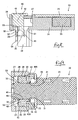
- As shown in Figures 15 and 16 of this specification, when two
housings terminal fittings 103 of thefirst housing 101 are short-circuited by shortingterminals 104, and a fitting detectingmember 105 and a short-circuit releasing member 106 are attached to thesecond housing 102 in a temporarily retained state. When attachment is to take place, the twohousings circuit releasing member 106 is pushed in towards areturn spring 107, thereby releasing the short-circuiting state. Finally, the fitting detectingmember 105 is pushed in. Pushing in the fitting detectingmember 105 causes a retainingmember 105A thereof to engage with a retainingmember 106A of a short-circuit releasing member 106, this short-circuit member 106 being locked in a state whereby it is pressed against thereturn spring 107. Thereturn spring 107 is not shown in Figure 16 for reasons of clarity. - If the two
housings member 105, preventing thefitting detecting member 105 from being pushed in. By this means, the half-fitted state can be detected. Furthermore, if one lets go of the short-circuit releasing member 106 which has been pushed in, thereturn spring 107 pushes the short-circuit releasing member 106 out to a temporary retaining position, and theterminal fittings 103 return to their short-circuiting state. - When the two
housings members return spring 107 moves the short-circuit releasing member 106 from a short-circuit releasing position to a position allowing short-circuiting to occur, and theterminal fittings 103 are short-circuited. - In the conventional connector, the
return spring 107 is the means to return the short-circuit releasing member 106 to the position allowing short-circuiting to occur. Thisreturn spring 107 is provided as a component separate from the short-circuit releasing member 106. Consequently, there is a problem that the number of components is large. - Furthermore, separate operations are required to push in the
fitting detecting member 105 and the short-circuiting member 106, and operability is consequently poor. - According to the invention there is provided an electrical connector comprising two housings adapted for mutual fitting and having a resilient latch movable to a locking position to retain said housings in a fitted condition, and movable to non-locking position during movement of said housings through a half-fitted condition, the connector including a detecting member provided on one of said housings and movable from a retracted to an advanced position, the latch preventing movement of the detecting member when in the non-locking position, and permitting movement of the detecting member when in the locking position, and the connector further including a short-circuit releasing member adapted to cause or release a short-circuit condition between terminals of the other of said housings, wherein said short-circuit releasing member is engageable by said detecting member on movement from the retracted to the advanced condition, to move from a short-circuiting condition to a state in which the short-circuit condition is released. Preferably the short-circuit releasing member includes a resilient arm which deflects during movement of the detecting member from a retracted to an advanced condition.
- The short-circuit releasing member is preferably 'U' shaped, having two such resilient arms, and insertable in one of said housings in the direction of the engagement axis of the housings. A projection of this 'U' shaped member is preferably engageable in a corresponding aperture of the associated housing to prevent lateral movement thereof. The arms of the 'U' shaped member are preferably deflectable apart to release the short-circuit condition, the tips of the arms preferably having a ramp surface for engagement with a short-circuit member and for moving the short-circuit member from a short-circuiting to a non-short circuiting condition.
- Other features of the invention will be apparent from the following description of a preferred embodiment shown by way of example only in the accompanying drawings in which:
- Figure 1 is a disassembled diagonal view of
embodiment 1. - Figure 2 is a diagonal view of a short-circuit releasing member and female terminal fittings attached to a female housing.
- Figure 3 is a diagonal view of the female housing covered by a cover.
- Figure 4 is a diagonal view of a fitting detecting member attached in a waiting position.
- Figure 5 is a diagonal view of the fitting detecting member which has been moved to a detecting position.
- Figure 6 is a vertical cross-sectional view of the fitting detecting member in the waiting position.
- Figure 7 is a vertical cross-sectional view of the fitting detecting member in the waiting position.
- Figure 8 is a vertical cross-sectional view of the fitting detecting member which has been moved to the detecting position.
- Figure 9 is a horizontal cross-sectional view of the fitting detecting member in the waiting position.
- Figure 10 is a horizontal cross-sectional view of the fitting detecting member which has been moved to the detecting position.
- Figure 11 is a front view of releasing members of the short-circuit releasing member which are in a position allowing short-circuiting to occur.
- Figure 12 is a front view of the releasing members of the short-circuit releasing member which have moved to a short-circuit releasing position.
- Figure 13 is a plan view showing the short-circuit releasing operation of the releasing member.
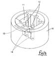
- Figure 14 is a diagonal view of a male housing.
- Figure 15 is a cross-sectional view of a conventional example.
- Figure 16 is a cross-sectional view of the conventional example.
-
- A connector of the present embodiment is provided with a
male housing 10 and afemale housing 20, these twohousings - The
male housing 10 is made from plastic. As shown in Figures 13 and 14, thismale housing 10 has arecess 11 opening onto its upper face. A left and right pair of upwardly protruding male terminal fittings 12 (the terminal fittings of the present invention) and a shortingterminal 13 are housed within thisrecess 11. The shortingterminal 13 has a pair ofresilient contacts 14 capable of making resilient contact with the side with themale terminal fittings 12. When the twohousings resilient contacts 14 make contact with the pair ofmale terminal fittings 12, causing a short-circuiting state therebetween. Furthermore, as will be explained, when the twohousings resilient contacts 14 are bent by a short-circuit releasing member 50 so as to become separated from themale terminal fittings 12, thereby releasing the short-circuiting state of the twomale terminal fittings 12. - The
female housing 20 is provided with a left and right pair of femaleterminal fittings 60 capable of making contact with themale terminal fittings 12, aferrite core 63, the short-circuit releasing member 50, and a fitting detectingmember 40. Thefemale housing 20 is made from plastic, and is composed of amain body 21 which is long in an anterior-posterior direction, and afitting member 22 which extends downwards from an anterior end of themain body 21 and which fits into therecess 11 of themale housing 10. Acavity 23 is formed within themain body 21 and thefitting member 22, thiscavity 23 having an L-shape when viewed from the side and being open to an upper face of thefemale housing 20. Housed within thecavity 23 are thefemale terminal fittings 60, ends ofelectric wires 61 that are connected to thefemale terminal fittings 60, and theferrite core 63. Further, the open portion of thecavity 23 is covered by acover 25 that is joined to thefemale housing 20 by ahinge 24. - The female
terminal fittings 60 have an L-shape when viewed from the side, the posterior ends thereof being crimped to theelectric wires 61. When the twohousings shaped members 62 of thefemale terminal fittings 60 fit with themale terminal fittings 12. Theferrite core 63, which is for noise reduction, has a left and right pair ofattachment holes 64 passing therethrough in an anterior-posterior direction, theelectric wire 61 passing through theseattachment holes 64. - A pair of left and
right side walls 26 are formed at an anterior end portion of themain body 21 of thefemale housing 20, andattachment spaces 27 are formed between the anterior end portion of themain body 21 and outer side faces of theside walls 26. Approximately the entirety of the upper faces of theattachment spaces 27 formed from theside walls 26 is open, lower faces thereof formingbase walls 28 which have portions thereof open. A detectingposition stopping groove 29 and a waitingposition stopping groove 30 are formed in two locations, at the anterior and posterior respectively, of each of left and right inner side faces of theside walls 26. Stoppingribs 42A of the fitting detectingmember 40 can fit into the detectingposition stopping grooves 29 and the waitingposition stopping grooves 30. Detectingmember escape holes 31, releasingmember escape holes 32 and stoppingmember escape holes 33 are formed in thebase walls 28. These detecting member escape holes 31 open out along outer side faces of themain body 21 of thefemale housing 20. The releasing member escape holes 23 also open out along the outer side faces of themain body 21 and are located to the anterior of the detecting member escape holes 31. The stopping member escape holes 33 open out along the left and right side faces of theside walls 26. - Furthermore, a locking
member 35 extends downwards from eachbase wall 28. Each lockingmember 35 has a detectingspace 14 which allows detectingmembers 43 to be fitted between the lockingmembers 35 and the outer side faces of themain body 21 with only a small space remaining therebetween. While themale housing 10 is in the process of being fitted with thefemale housing 20, the lockingmembers 35 make contact with lock receiving members (not shown) of themale housing 10, and are thereby bent inwards. When the twohousings members 35 return, as a result of their own resilient returning force, to their original position, leaving the detectingspaces 34 empty. - The fitting detecting
member 40 is composed of a horizontalupper face plate 41, a pair of guidingmembers 42 that extend downwards from anterior ends of left and right side edges of theupper face plate 41, the detectingmembers 43 that protrude downwards from posterior ends of the guidingmembers 42, and a pair of stoppingmembers 44 that protrude downwards from posterior ends of the left and right side edges of theupper face plate 41. Inner faces of the guidingmembers 42 form pressing faces 45 for pressing releasing members 52 (to be explained) of the short-circuit releasing member 50. Anterior ends of thesepressing faces 45 form guidinginclined faces 46 which are taper shaped when viewed from above. Furthermore, the pressing faces 45 join in a unified manner with inner faces of the detectingmembers 43. The stoppingribs 42A are formed on outer faces of the guidingmembers 42. These stoppingribs 42A maintain the fitting detectingmember 40 in a waiting position and a detecting position. - After the
cover 25 is closed, thefitting detecting member 40 is attached to thefemale housing 20 with the guidingmembers 42, the detectingmembers 43, and the stoppingmembers 44 fitting from above into theattachment spaces 27, and theupper face plate 41 covering an upper face of thecover 25. In the attached state, the stoppingmembers 44 bend resiliently inwards, stoppingprotrusions 44A located at lower ends thereof passing through the stopping member escape holes 33. These stoppingprotrusions 44A engage with edges of the stopping member escape holes 33, thereby preventing the fitting detectingmember 40 from moving upwards relative to thefemale housing 20. Further, the inner and outer faces of the guidingmembers 42 are adjacent, respectively, to the outer side faces of themain body 21 above thebase walls 28 and inner side faces of theside walls 26. Consequently, thefitting member 40 is prevented from moving to the left or right of thefemale housing 20. Moreover, the stoppingribs 42A fit into the waitingposition stopping grooves 30, thereby maintaining the fitting detectingmember 40 in the waiting position without its moving to the anterior or posterior. The fitting detectingmember 40, which is maintained in the waiting position, can be moved horizontally in an anterior direction to the detecting position, theside walls 26 bending resiliently outwards and the stoppingribs 42A make sliding contact with inner faces thereof. The stoppingribs 42A then fit with the detectingposition stopping grooves 29, thereby maintaining the fitting detectingmember 40 in the detecting position without its moving to the anterior or posterior. - The detecting
members 43 pass through the detecting member escape holes 31 and protrude downwards from thebase walls 28. These detectingmembers 43 are located so as to fit into the detectingspaces 34 positioned between the locking members 35 (which are in a free state when viewed from their front faces) and themain body 21. When the fitting detectingmember 40 is in the waiting position, the detectingmembers 43 are located to the posterior of the lockingmembers 35 when viewed from the side (the right side in Figure 7). However, when the fitting detectingmember 40 has been moved to the detecting position, the detectingmembers 43 enter the detectingspaces 34 and overlap with the lockingmembers 35 when viewed from the side. Furthermore, as the twohousings members 35 are in a state whereby they are bent inwards so as to enter the detecting spaces 34 (that is, in a half-fitting state), the detectingmembers 43 make contact with posterior ends of the lockingmembers 35, thereby preventing the lockingmembers 35 from entering the detectingspaces 34. Consequently, thefitting detecting member 40 is prevented from entering the detecting position. - The short-
circuit releasing member 50, which has an inverted U-shape when viewed from the anterior, is formed in a unified manner from anattachment member 51 that is long and narrow in a left-right direction, and the pair of releasingmembers 52 that protrude downwards in a mutually parallel manner from left and right ends of theattachment member 51. The releasingmembers 52 are usually in a position allowing short-circuiting to occur, but are capable of being bent resiliently inwards relative to the attachment member 51 (that is, the releasingmembers 52 are bent towards one another) to a short-circuit releasing position. The releasingmembers 52 return from the short-circuit releasing position to the position allowing short-circuiting to occur due to their own resilient returning force. The short-circuit releasing member 50 may be made from either metal or plastic. - Pressing
protrusions 53 are formed on both outer faces of the releasingmembers 52. Thesepressing protrusions 53 are formed at height allowing them to engage with the pressing faces 45 of the fitting detectingmember 40. Contactingmembers 54 extend inwards from anterior edges of lower ends of the releasingmembers 52. These contactingmembers 54 have guiding inclined faces 55 which are taper shaped when viewed from above. The space between both inner sides of the contactingmembers 54 is usually (that is, when the releasingmembers 52 are in the position allowing short-circuiting to occur) greater than the dimensions between outer sides of the pair ofresilient contacts 14 of the shortingterminal circuit 13 of themale housing 10. However, when the releasingmembers 52 are in a state whereby they have been moved to the short-circuit releasing position, the pitch between the contactingmembers 54 is the same as the pitch between theresilient contacts 14. That is, when the short-circuit releasing member 50 is in the short-circuit releasing position, the contactingmembers 54 do not make contact with theresilient contacts 14 of the shortingterminal 13 even if the twohousings circuit releasing member 50 is moved resiliently to the short-circuit releasing position when the twohousings members 54 engage from the sides with theresilient contacts 14 and press these towards the anterior (in a direction away from the male terminal fittings 12) by means of the guiding inclined faces. - The short-
circuit releasing member 50 is attached by fitting anattachment protrusion 56, which extends downwards from an anterior edge of theattachment member 51, into anattachment groove 36 of thefemale housing 20, and by inserting the two releasingmembers 52 into theattachment spaces 27. The attachment operation of the short-circuit releasing member 50 is performed before the fitting detectingmember 40 is attached and before the open portion of thecavity 23 is covered by thecover 25. After thefitting detecting member 50 has been attached, thecover 25 pressed down on theattachment member 51 thereof from above, thereby preventing the fitting detectingmember 50 from moving upwards. Theattachment protrusion 56 fits into theattachment groove 36, thereby preventing the fitting detectingmember 50 from moving in an anterior-posterior or left-right direction. - When the short-
circuit releasing member 50 is in the attached state, the releasingmembers 52 pass through the releasing member escape holes 32 and extend downwards. Viewed from above, the outer faces of the releasingmembers 52 are located in approximately the same position as the outer side faces of themain body 21, thepressing protrusions 53 protruding outwards relative to the outer side faces of themain body 21 so as to be located in a position whereby they can make contact with the pressing faces 45. When the fitting detectingmember 40 is in the waiting state, thepressing protrusions 53 are iocated in the vicinity of the guiding inclined faces 46 at the anterior ends of the guidingmembers 42. When the fitting detectingmember 40 is moved from the waiting position to the detecting position, the pressing faces 45 make contact with thepressing protrusions 53, and as a result the releasingmembers 52 are pushed in resiliently from the position allowing short-circuiting to occur to the short-circuit releasing position. - As the short-
circuit releasing member 50 is moving from the waiting position to the detecting position, the guiding inclined faces 46 and the pressing faces 45 make contact with thepressing protrusions 53 before the anterior edges of the detectingmembers 43 of the fitting detectingmember 40 reach the posterior edge of the lockingmember 35, and the releasingmembers 52 are moved to the short-circuit releasing position. - When the two
housings fitting member 22 is fitted into therecess 11 while thefitting detecting member 40 is in a state whereby it has been moved to the waiting position. During this fitting operation, the lockingmembers 35 are bent temporarily inwards from a locking position to a non-locking position. When the twohousings members 35 return resiliently to the locking position, thereby locking the twohousings members 52 of the short-circuit releasing member 50 are in the position allowing short-circuiting to occur. Consequently, the maleterminal fittings 12 of themale housing 10 are short-circuited by the shortingterminal 13. - Next, the
fitting detecting member 40 is slid to the anterior to the detecting position. Immediately after this sliding operation has begun, the guiding inclined faces 46 and the pressing faces 45 of the fitting detectingmember 40 make contact in turn with the pressingprotrusions 53. As the fitting detectingmember 40 is being slid, the releasingmembers 52 are pressed resiliently into the short-circuit releasing position. As the releasingmembers 52 move, the guiding inclined faces 53 of the contactingmembers 54 of the releasingmembers 52 make contact from the sides with theresilient contacts 14 of the shortingterminal 13. These guiding inclined faces 55 press against theresilient contacts 14, causing them to bend away from the maleterminal fittings 12. By this means, the short-circuiting state of the maleterminal fittings 12 is released. - In this short-circuit releasing state, the resilient returning force of the
resilient contacts 14 exerts a pushing force in a posterior direction on the contactingmembers 54 of the short-circuit releasing member 50. However, when the releasingmembers 52 are in the short-circuit releasing position, the releasingmembers 52 and the contactingmembers 54 are located so as to make contact with the anterior end face of themain body 21 of thefemale housing 20. Consequently, the releasingmember 52 and the contactingmembers 54 are prevented from moving to the posterior, and theresilient contacts 14 are reliably maintained in a position whereby they do not make contact with the maleterminal fittings 12. - Furthermore, the short-circuit releasing operation of the short-
circuit releasing member 50 is completed before the fitting detectingmember 40 reaches the detecting position. After the short-circuit releasing operation is completed, the insertion begins of the detectingmembers 43 of the fitting detectingmember 40 into the detectingspaces 34 between the lockingmembers 35 and themain body 21. When the fitting detectingmember 40 reaches the detecting position, the stoppingribs 42A fit with a click into the detectingposition stopping grooves 29 located at the anterior. This click informs the operator that the fitting detectingmember 40 has reached the detecting position and, simultaneously, the fact of the fitting detectingmember 40 reaching the detecting position informs the operator that the twohousings housings terminal fittings 12, and the fitting detecting operation of the twohousings - In the case where the two
housings members 35 are in the non-locking position within the detectingspaces 34. As a result, immediately after the fitting detectingmember 40 has been slid a short way towards the detecting position, the detectingmembers 43 strike against posterior ends of the lockingmembers 35 which are in the non-locking position, thereby preventing the fitting detectingmember 40 from moving further towards the anterior. The fact that the fitting detectingmember 40 has moved less than the correct distance will inform the operator that the twohousings ribs 42A fitting into the anterior located detectingposition stopping grooves 29 will not be heard, thereby allowing the half-fitted state to be detected. - When the two
housings fitting detecting member 40 is first slid towards the posterior from the detecting position to the waiting position. Simultaneously, the pressing faces 45 and the guiding inclined faces 46 of the fitting detectingmember 40 are separated, in turn, from the pressingprotrusions 53. As a result, the releasingmembers 52, due to their own resilient returning force, move resiliently outwards from the short-circuit releasing position to the position allowing short-circuiting to occur. As the releasingmembers 52 return to their original position, the contactingmembers 54 are released, in an outwards direction, from theresilient contacts 14. Theresilient contacts 14 move towards the posterior due to their own resilient returning force and make contact with the maleterminal fittings 12. Consequently, the maleterminal fittings 12 are again in the short-circuiting state. - When the fitting detecting
member 40 is moved from the detecting position to the waiting position, the releasingmembers 52 of the short-circuit releasing member 50 move as a result of their resilient returning force from the short-circuiting releasing position to the position allowing short-circuiting to occur. Consequently, a separate means for moving the releasingmembers 52 to the position allowing short-circuiting to occur is not required. By this means, the number of components is reduced. Furthermore, when the twohousings members 52 are pushed from the position allowing short-circuiting to occur to the short-circuit releasing position as thefitting detecting member 40 is moved from the waiting position to the detecting position. Consequently, both the detecting operation of the fitting detectingmember 40 and the short-circuit releasing operation are performed with a single action. By this means, operability is improved. - The present invention is not limited to the embodiments described above with the aid of figures. For example, the possibilities described below also lie within the technical range of the present invention. In addition, the present invention may be embodied in various other ways without deviating from the scope thereof.
- (1) In the embodiment described above, the detecting operation of the fitting detecting member automatically moves the releasing members of the short-circuit releasing member to the short-circuit releasing position. However, in the invention, the short-circuit releasing operation and the fitting detecting operation may equally well be performed separately.
- (2) In the embodiment described above, the releasing members are capable of returning to the position allowing short-circuiting to occur as a result of their own resilient returning force. However, in the invention, the releasing members may equally well be returned to the position allowing short-circuiting to occur by a spring means that is separate from the releasing members.
-
Claims (11)
- An electrical connector comprising two housings (10,20) adapted for mutual fitting and having a resilient latch (35) movable to a locking position to retain said housings in a fitted condition, and movable to non-locking position during movement of said housings through a half-fitted condition, the connector including a detecting member (40) provided on one of said housings (20) and movable from a retracted to an advanced position, the latch (35) preventing movement of the detecting member (40) when in the non-locking position, and permitting movement of the detecting member (40) when in the locking position, and the connector further including a short-circuit releasing member (50) adapted to cause or release a short-circuit condition between terminals (12) of the other of said housings (10), wherein said short-circuit releasing member (50) is engageable by said detecting member (40) on movement from the retracted to the advanced condition, to move from a short-circuiting condition to a state in which the short-circuit condition is released.
- An electrical connector according to claim 1 wherein said short-circuit releasing member (50) includes a resilient arm (52), and said detecting member (40) deflects said arm (52) during movement from the retracted to the advanced condition, thereby to release said short- circuit.
- An electrical connector according to claim 2 wherein said resilient arm (52) has a protrusion (53), and said detecting member (40) includes a ramp (46) engageable with said protrusion (53) to deflect said arm.
- An electrical connector according to claim 2 wherein said short-circuit releasing member (50) is 'U' shaped, a resilient arm (52) being constituted by each free end thereof.
- An electrical connector according to claim 4 wherein the arms (52) of said short-circuit releasing member (50) are deflected apart by said detecting member (40) in the advanced condition.
- An electrical connector according to claim 4 or claim 5 wherein the tips (54) of each free end of the short-circuit releasing member (50) include ramp faces (55) for engagement with a short-circuit member (13) of the other of said housings (10).
- An electrical connector according to any preceding claim, said housings (10,20) being engageable on an attachment axis, said detecting member being movable perpendicular to the direction of said axis from the retracted to the advanced condition, and said short-circuit releasing member being movable in a direction at right angles to said attachment axis and to the direction of movement of said detecting member (40) in response to movement of said detecting member (40).
- An electrical connector according to claim 7 wherein said short-circuit releasing member (50) is insertable in one of said housings in the direction of said attachment axis.
- An electrical connector according to claim 8 wherein said short-circuit releasing member (50) includes a protrusion (56) extending in the direction of said axis and engageable in an aperture (36) of said one of said housings (20) to prevent movement thereof in the plane at right angles to said axis.
- An electrical connector according to any preceding claim wherein said detecting member (40) is resiliently latchable in the retracted and in the advanced conditions.
- An electrical connector according to any preceding claim wherein said detecting member (40) is movable in the advanced condition into a bending space (34) of said resilient latch (35) thereby to prevent movement of said latch when in the locking position.
Applications Claiming Priority (2)
| Application Number | Priority Date | Filing Date | Title |
|---|---|---|---|
| JP2000001717A JP2001196142A (en) | 2000-01-07 | 2000-01-07 | connector |
| JP2000001717 | 2000-01-07 |
Publications (1)
| Publication Number | Publication Date |
|---|---|
| EP1115181A1 true EP1115181A1 (en) | 2001-07-11 |
Family
ID=18530912
Family Applications (1)
| Application Number | Title | Priority Date | Filing Date |
|---|---|---|---|
| EP00310656A Withdrawn EP1115181A1 (en) | 2000-01-07 | 2000-11-30 | Electrical connector |
Country Status (3)
| Country | Link |
|---|---|
| US (1) | US6439914B2 (en) |
| EP (1) | EP1115181A1 (en) |
| JP (1) | JP2001196142A (en) |
Cited By (6)
| Publication number | Priority date | Publication date | Assignee | Title |
|---|---|---|---|---|
| EP1605555A1 (en) * | 2004-06-07 | 2005-12-14 | Delphi Technologies, Inc. | Electrical connector |
| EP1705757A1 (en) * | 2005-03-23 | 2006-09-27 | Sumitomo Wiring Systems, Ltd. | A connector and a method of assembling it |
| EP2805385A4 (en) * | 2012-01-18 | 2015-10-28 | Molex Inc | Connector |
| EP3118943A1 (en) * | 2015-07-15 | 2017-01-18 | Delphi International Operations Luxembourg S.à r.l. | Electrical plug connector for a safety restraint system |
| WO2017207453A1 (en) * | 2016-05-31 | 2017-12-07 | Robert Bosch Gmbh | Plug connector system with display element |
| WO2021105190A1 (en) * | 2019-11-28 | 2021-06-03 | Amphenol-Tuchel Electronics Gmbh | Secondary locking apparatus |
Families Citing this family (17)
| Publication number | Priority date | Publication date | Assignee | Title |
|---|---|---|---|---|
| JP2003203722A (en) * | 2001-12-31 | 2003-07-18 | Jst Mfg Co Ltd | Plug for electrical connector and method of assembling the same |
| JP2003249308A (en) * | 2002-02-25 | 2003-09-05 | Tyco Electronics Amp Kk | Electrical connector assembly |
| DE10227016B4 (en) * | 2002-06-17 | 2004-06-03 | Amphenol-Tuchel Electronics Gmbh | Electrical connector |
| DE102004031464B3 (en) * | 2004-06-30 | 2006-02-09 | Tyco Electronics Amp Gmbh | Lockable plug connection |
| US7351089B2 (en) * | 2006-04-28 | 2008-04-01 | Delphi Technologies, Inc. | Electrical connector having a CPA plug |
| US7682205B2 (en) * | 2007-11-15 | 2010-03-23 | Tyco Electronics Corporation | Multi position electrical connector assembly |
| SG153708A1 (en) * | 2007-12-28 | 2009-07-29 | Mea Technologies Pte Ltd | First connector, second connector, and electrical connecting device |
| JP5150428B2 (en) * | 2008-09-17 | 2013-02-20 | 矢崎総業株式会社 | connector |
| US8282411B2 (en) * | 2010-03-01 | 2012-10-09 | International Engine Intellectual Property Company, Llc. | Connector position assurance lock |
| JP5644657B2 (en) * | 2011-05-10 | 2014-12-24 | 住友電装株式会社 | Automotive electrical equipment seal cover |
| JP5692598B2 (en) * | 2011-07-25 | 2015-04-01 | 住友電装株式会社 | Mating detection structure |
| JP7014139B2 (en) * | 2018-11-27 | 2022-02-01 | 住友電装株式会社 | connector |
| JP7236034B2 (en) * | 2019-10-23 | 2023-03-09 | 株式会社オートネットワーク技術研究所 | branch connector |
| USD949115S1 (en) * | 2019-11-25 | 2022-04-19 | TSI Products, Inc. | Control frame |
| US11826077B2 (en) | 2020-03-23 | 2023-11-28 | Texas Scottish Rite Hospital For Children | External fixation strut |
| JP2024064957A (en) * | 2022-10-28 | 2024-05-14 | ヒロセ電機株式会社 | Crimp terminal, terminal assembly and connector |
| DE102023113785A1 (en) * | 2023-05-25 | 2024-11-28 | Md Elektronik Gmbh | ANGLED AND SEALED CONNECTOR ARRANGEMENT |
Citations (4)
| Publication number | Priority date | Publication date | Assignee | Title |
|---|---|---|---|---|
| EP0734101A2 (en) * | 1995-03-20 | 1996-09-25 | Molex Incorporated | Electrical connector position assurance system |
| EP0734100A2 (en) * | 1995-03-20 | 1996-09-25 | The Whitaker Corporation | Electrical connector with terminal position assurance |
| DE19617820A1 (en) * | 1996-05-03 | 1997-11-13 | Framatome Connectors Int | Electrical connector with secondary latching and lateral cable outlet for vehicle airbag system |
| EP0902506A2 (en) * | 1997-09-09 | 1999-03-17 | Sumitomo Wiring Systems, Ltd. | Connector |
Family Cites Families (1)
| Publication number | Priority date | Publication date | Assignee | Title |
|---|---|---|---|---|
| US6276953B1 (en) * | 1997-12-04 | 2001-08-21 | Thoma & Betts International, Inc. | Orientationless squib connector assembly for automotive air bag assemblies |
-
2000
- 2000-01-07 JP JP2000001717A patent/JP2001196142A/en active Pending
- 2000-11-30 EP EP00310656A patent/EP1115181A1/en not_active Withdrawn
- 2000-12-15 US US09/736,172 patent/US6439914B2/en not_active Expired - Fee Related
Patent Citations (4)
| Publication number | Priority date | Publication date | Assignee | Title |
|---|---|---|---|---|
| EP0734101A2 (en) * | 1995-03-20 | 1996-09-25 | Molex Incorporated | Electrical connector position assurance system |
| EP0734100A2 (en) * | 1995-03-20 | 1996-09-25 | The Whitaker Corporation | Electrical connector with terminal position assurance |
| DE19617820A1 (en) * | 1996-05-03 | 1997-11-13 | Framatome Connectors Int | Electrical connector with secondary latching and lateral cable outlet for vehicle airbag system |
| EP0902506A2 (en) * | 1997-09-09 | 1999-03-17 | Sumitomo Wiring Systems, Ltd. | Connector |
Cited By (9)
| Publication number | Priority date | Publication date | Assignee | Title |
|---|---|---|---|---|
| EP1605555A1 (en) * | 2004-06-07 | 2005-12-14 | Delphi Technologies, Inc. | Electrical connector |
| EP1705757A1 (en) * | 2005-03-23 | 2006-09-27 | Sumitomo Wiring Systems, Ltd. | A connector and a method of assembling it |
| EP2805385A4 (en) * | 2012-01-18 | 2015-10-28 | Molex Inc | Connector |
| EP3118943A1 (en) * | 2015-07-15 | 2017-01-18 | Delphi International Operations Luxembourg S.à r.l. | Electrical plug connector for a safety restraint system |
| CN106654765A (en) * | 2015-07-15 | 2017-05-10 | 德尔福国际业务卢森堡公司 | Electrical plug connector for a safety restraint system |
| US9780502B2 (en) | 2015-07-15 | 2017-10-03 | Delphia International Operations Luxembourg S.A.R.L. | Electrical plug connector for a safety restraint system |
| CN106654765B (en) * | 2015-07-15 | 2020-06-26 | 德尔福国际业务卢森堡公司 | Electrical plug connector for safety restraint system |
| WO2017207453A1 (en) * | 2016-05-31 | 2017-12-07 | Robert Bosch Gmbh | Plug connector system with display element |
| WO2021105190A1 (en) * | 2019-11-28 | 2021-06-03 | Amphenol-Tuchel Electronics Gmbh | Secondary locking apparatus |
Also Published As
| Publication number | Publication date |
|---|---|
| US6439914B2 (en) | 2002-08-27 |
| JP2001196142A (en) | 2001-07-19 |
| US20010007801A1 (en) | 2001-07-12 |
Similar Documents
| Publication | Publication Date | Title |
|---|---|---|
| US6439914B2 (en) | Connector having a short-circuiting element | |
| US7530861B2 (en) | Connector | |
| EP1117159B1 (en) | Connector | |
| US6364683B1 (en) | Electrical connector | |
| US11456553B2 (en) | Low profile high voltage connector and method for assemblying thereof | |
| US7980880B2 (en) | Connector | |
| JP4876985B2 (en) | connector | |
| EP1986288B1 (en) | A shorting terminal, a connector and an assembling method therefor | |
| EP0923169B1 (en) | Connector containing a short-circuit terminal | |
| JPH03116672A (en) | Electric connector | |
| US6325680B1 (en) | Female contact for an electrical connector | |
| CN101218714B (en) | Connector Assemblies with Terminal Position Assurance Devices | |
| EP0848458B1 (en) | Connector with engagement detection means | |
| JPH02247993A (en) | Brached connector mechanism | |
| JPH09306582A (en) | Connector | |
| JP3596702B2 (en) | Connector mating detection structure | |
| JP2002324614A (en) | Connector | |
| US6953364B2 (en) | Connector, a shorting terminal and a method of assembling it | |
| EP1801926B1 (en) | A connetor and connector assembly | |
| US6669508B2 (en) | Connector | |
| US20220059963A1 (en) | Connector | |
| JP2006164611A (en) | Connector | |
| JP3193271B2 (en) | connector | |
| JP2595101Y2 (en) | Low insertion force type electrical connector | |
| JP2005190821A (en) | Connector assembly |
Legal Events
| Date | Code | Title | Description |
|---|---|---|---|
| PUAI | Public reference made under article 153(3) epc to a published international application that has entered the european phase |
Free format text: ORIGINAL CODE: 0009012 |
|
| 17P | Request for examination filed |
Effective date: 20001215 |
|
| AK | Designated contracting states |
Kind code of ref document: A1 Designated state(s): AT BE CH CY DE DK ES FI FR GB GR IE IT LI LU MC NL PT SE TR |
|
| AX | Request for extension of the european patent |
Free format text: AL;LT;LV;MK;RO;SI |
|
| STAA | Information on the status of an ep patent application or granted ep patent |
Free format text: STATUS: THE APPLICATION HAS BEEN WITHDRAWN |
|
| 18W | Application withdrawn |
Withdrawal date: 20011212 |