EP1115037A2 - Image forming apparatus - Google Patents
Image forming apparatus Download PDFInfo
- Publication number
- EP1115037A2 EP1115037A2 EP01100321A EP01100321A EP1115037A2 EP 1115037 A2 EP1115037 A2 EP 1115037A2 EP 01100321 A EP01100321 A EP 01100321A EP 01100321 A EP01100321 A EP 01100321A EP 1115037 A2 EP1115037 A2 EP 1115037A2
- Authority
- EP
- European Patent Office
- Prior art keywords
- fixing
- image
- image forming
- rotating member
- magnetic flux
- Prior art date
- Legal status (The legal status is an assumption and is not a legal conclusion. Google has not performed a legal analysis and makes no representation as to the accuracy of the status listed.)
- Granted
Links
- 230000004907 flux Effects 0.000 claims abstract description 23
- 239000000463 material Substances 0.000 claims abstract description 16
- 230000015572 biosynthetic process Effects 0.000 claims abstract description 13
- 238000000034 method Methods 0.000 description 13
- 230000008569 process Effects 0.000 description 10
- 239000002184 metal Substances 0.000 description 8
- 229910052751 metal Inorganic materials 0.000 description 8
- 238000010438 heat treatment Methods 0.000 description 6
- 239000002932 luster Substances 0.000 description 5
- 230000004044 response Effects 0.000 description 4
- XEEYBQQBJWHFJM-UHFFFAOYSA-N Iron Chemical compound [Fe] XEEYBQQBJWHFJM-UHFFFAOYSA-N 0.000 description 3
- 230000006698 induction Effects 0.000 description 3
- 238000011112 process operation Methods 0.000 description 3
- 230000007423 decrease Effects 0.000 description 2
- 238000001514 detection method Methods 0.000 description 2
- 230000020169 heat generation Effects 0.000 description 2
- 239000000696 magnetic material Substances 0.000 description 2
- 239000004810 polytetrafluoroethylene Substances 0.000 description 2
- 229920001343 polytetrafluoroethylene Polymers 0.000 description 2
- 239000011347 resin Substances 0.000 description 2
- 229920005989 resin Polymers 0.000 description 2
- 238000004904 shortening Methods 0.000 description 2
- 230000004075 alteration Effects 0.000 description 1
- 230000005540 biological transmission Effects 0.000 description 1
- 238000006243 chemical reaction Methods 0.000 description 1
- 210000000078 claw Anatomy 0.000 description 1
- 238000004040 coloring Methods 0.000 description 1
- 238000009826 distribution Methods 0.000 description 1
- 230000004927 fusion Effects 0.000 description 1
- 229910052736 halogen Inorganic materials 0.000 description 1
- 150000002367 halogens Chemical class 0.000 description 1
- 238000009413 insulation Methods 0.000 description 1
- 229910052742 iron Inorganic materials 0.000 description 1
- 230000007246 mechanism Effects 0.000 description 1
- 238000012986 modification Methods 0.000 description 1
- 230000004048 modification Effects 0.000 description 1
- 230000002093 peripheral effect Effects 0.000 description 1
- 230000035699 permeability Effects 0.000 description 1
- 229920001296 polysiloxane Polymers 0.000 description 1
- 239000000843 powder Substances 0.000 description 1
- 230000005855 radiation Effects 0.000 description 1
- 230000003578 releasing effect Effects 0.000 description 1
- 239000012260 resinous material Substances 0.000 description 1
- 238000000926 separation method Methods 0.000 description 1
- 229910001220 stainless steel Inorganic materials 0.000 description 1
- 239000010935 stainless steel Substances 0.000 description 1
- 230000001360 synchronised effect Effects 0.000 description 1
- 238000010792 warming Methods 0.000 description 1
Images



Classifications
-
- G—PHYSICS
- G03—PHOTOGRAPHY; CINEMATOGRAPHY; ANALOGOUS TECHNIQUES USING WAVES OTHER THAN OPTICAL WAVES; ELECTROGRAPHY; HOLOGRAPHY
- G03G—ELECTROGRAPHY; ELECTROPHOTOGRAPHY; MAGNETOGRAPHY
- G03G15/00—Apparatus for electrographic processes using a charge pattern
- G03G15/20—Apparatus for electrographic processes using a charge pattern for fixing, e.g. by using heat
- G03G15/2003—Apparatus for electrographic processes using a charge pattern for fixing, e.g. by using heat using heat
- G03G15/2014—Apparatus for electrographic processes using a charge pattern for fixing, e.g. by using heat using heat using contact heat
- G03G15/2053—Structural details of heat elements, e.g. structure of roller or belt, eddy current, induction heating
-
- G—PHYSICS
- G03—PHOTOGRAPHY; CINEMATOGRAPHY; ANALOGOUS TECHNIQUES USING WAVES OTHER THAN OPTICAL WAVES; ELECTROGRAPHY; HOLOGRAPHY
- G03G—ELECTROGRAPHY; ELECTROPHOTOGRAPHY; MAGNETOGRAPHY
- G03G15/00—Apparatus for electrographic processes using a charge pattern
- G03G15/20—Apparatus for electrographic processes using a charge pattern for fixing, e.g. by using heat
- G03G15/2003—Apparatus for electrographic processes using a charge pattern for fixing, e.g. by using heat using heat
- G03G15/2014—Apparatus for electrographic processes using a charge pattern for fixing, e.g. by using heat using heat using contact heat
- G03G15/2039—Apparatus for electrographic processes using a charge pattern for fixing, e.g. by using heat using heat using contact heat with means for controlling the fixing temperature
-
- G—PHYSICS
- G03—PHOTOGRAPHY; CINEMATOGRAPHY; ANALOGOUS TECHNIQUES USING WAVES OTHER THAN OPTICAL WAVES; ELECTROGRAPHY; HOLOGRAPHY
- G03G—ELECTROGRAPHY; ELECTROPHOTOGRAPHY; MAGNETOGRAPHY
- G03G15/00—Apparatus for electrographic processes using a charge pattern
- G03G15/20—Apparatus for electrographic processes using a charge pattern for fixing, e.g. by using heat
- G03G15/2003—Apparatus for electrographic processes using a charge pattern for fixing, e.g. by using heat using heat
- G03G15/2014—Apparatus for electrographic processes using a charge pattern for fixing, e.g. by using heat using heat using contact heat
- G03G15/2039—Apparatus for electrographic processes using a charge pattern for fixing, e.g. by using heat using heat using contact heat with means for controlling the fixing temperature
- G03G15/205—Apparatus for electrographic processes using a charge pattern for fixing, e.g. by using heat using heat using contact heat with means for controlling the fixing temperature specially for the mode of operation, e.g. standby, warming-up, error
-
- G—PHYSICS
- G03—PHOTOGRAPHY; CINEMATOGRAPHY; ANALOGOUS TECHNIQUES USING WAVES OTHER THAN OPTICAL WAVES; ELECTROGRAPHY; HOLOGRAPHY
- G03G—ELECTROGRAPHY; ELECTROPHOTOGRAPHY; MAGNETOGRAPHY
- G03G2215/00—Apparatus for electrophotographic processes
- G03G2215/20—Details of the fixing device or porcess
- G03G2215/2003—Structural features of the fixing device
- G03G2215/2016—Heating belt
- G03G2215/2035—Heating belt the fixing nip having a stationary belt support member opposing a pressure member
Definitions
- the present invention relates to an image forming apparatus such as a copying apparatus, a printer or the like, and more particularly to an apparatus employing fixing means provided with a rotating member heated by induction heating.
- the image forming apparatus based on the electrophotographic process is provided with a fixing device for fusion fixing toner to a transfer material, by applying heat and pressure while sandwiching and conveying the transfer material and the toner, borne on the transfer material and composed of a resinous material, a magnetic material, a coloring material etc. in a pressure contact portion (nip portion) of a fixing roller and a pressure roller maintained in mutual pressurized contact and in rotation.
- heating means a method of generating an eddy current in an electroconductive layer provided on the fixing roller by means of a magnetizing coil thereby generating Joule heat.
- the method allows to position the heat source very close to the toner, thereby being featured in shortening the time required by the surface temperature of the fixing roller to reach a temperature adequate for fixing at the start-up of the fixing device, in comparison with the conventional heat roller system employing a halogen lamp. It is also featured by a high heat efficiency because of the short and simple heat transmission path from the heat source to the toner.
- An object of the present invention is to provide an image forming apparatus capable of efficiently warming the rotating member of the fixing means.
- Another object of the present invention is to provide an image forming apparatus provided with unfixed image forming means for forming an unfixed image based on an image formation start signal, and fixing means for fixing the unfixed image formed by the unfixed image forming means on a recording material
- the fixing means includes a rotating member and a magnetic flux generating means for generating a magnetic flux by supplying power, wherein the magnetic flux generated by the magnetic flux generating means generates an eddy current in the rotating member, so that the rotating member generates heat by the eddy current, thereby an image on the recording material is heated, and wherein, in a stand-by state prior to an input of the image formation start signal, the rotating member stops rotation and the magnetic flux generating means is energized.
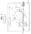
- Fig. 7 is a schematic view showing the configuration of an image forming apparatus embodying the present invention.
- the image forming apparatus of the present embodiment is a laser beam printer utilizing an electrophotographic process.
- the reference numeral 30 shows a host apparatus such as an image reading apparatus, a word processor, or a computer.
- An image formation start signal (print signal) is inputted to the image forming apparatus.
- An electrophotographic photosensitive member (hereinafter represented as photosensitive drum) 21 of rotating drum type, serving as an image bearing member, is rotated clockwise, as indicated by an arrow, with a predetermined peripheral speed (process speed) and, in the source of such rotation, uniformly charged to a predetermined negative dark potential V D by a primary charger 22.
- a laser beam scanner 23 outputs a laser beam L modulated according to a time-sequential digital electric image signal of the desired image information inputted from the host apparatus 30, thereby exposing in scanning the uniformly charged surface of the rotating photosensitive drum 21.
- the exposed portion in the uniformly charged surface of the rotating photosensitive drum 21 assumes a light portion potential V L with a smaller absolute value, whereby an electrostatic latent image corresponding to the desired image information is formed on the surface of the rotating photosensitive drum 21.
- the latent image is then subjected to reversal development in a developing device 24 with negatively charged powder toner (toner being deposited in the laser exposed portion of the light portion potential V L on the photosensitive drum surface), thereby being visualized as a toner image 4.
- sheet 5 constituting the recording material and fed from a sheet feeding tray is conveyed, with an appropriate timing synchronized with the rotation of the photosensitive drum 21, to the pressure contact nip portion (transfer portion) between the photosensitive drum 21 and the transfer roller 25 constituting a transfer member to which a transfer bias is supplied, whereby the toner image 4 formed on the photosensitive drum 21 is transferred in succession onto the surface of the sheet 5.
- the sheet 5 bearing the unfixed toner image 4 which is formed by image forming means composed of the components 21, 22, 23, 24, 25 etc. is separated from the surface of the rotating photosensitive drum 21 then is introduced into a fixing apparatus (image heating apparatus) R for fixing the toner image 4, and is discharged as an image formed object (print) from the apparatus.
- a fixing apparatus image heating apparatus
- Fig. 1 is a schematic cross-sectional view of the fixing apparatus R.
- a fixing roller 1 which is a rotating member, is composed of a rigid cylindrical metal core la of iron with an external diameter of 30 mm and a thickness of 1.0 mm, and may be provided with a layer 1b of fluorinated resin such as PTFE of 10 to 50 ⁇ m or PFA of 10 to 50 ⁇ m, in order to improve the releasing property of the surface.
- the metal core la of the fixing roller 1 may also be composed of another material of a relatively high magnetic permeability ⁇ and an appropriate resistivity p for example a magnetic material (magnetic metal) such as magnetic stainless steel.
- the metal core la of the fixing roller 1 is an electrically conductive layer.
- the pressure roller 2 constituting a back-up member, is composed of an iron core metal 2a of an external diameter of 20 mm with a silicone (Si) rubber layer 2a of a thickness of 5mm on the external periphery, eventually with a fluorinated resin layer 2c for example of PTFE of 10 to 100 ⁇ m or PFA of 10 to 100 ⁇ m, with an entire external diameter of about 30 mm.
- the fixing roller 1 and the pressure roller 2 are rotatably supported, in which the fixing roller is driven.
- the pressure roller 2 is maintained in contact with the surface of the fixing roller 1 and is rotated by the friction at the pressure contact portion (nip portion) N.
- the pressure roller 2 is biased toward the rotary shaft of the fixing roller 1 by an unrepresented mechanism utilizing for example springs.
- a conveying guide 3 is provided in such a position as to guide the sheet, conveyed while supporting the unfixed toner image 4, to the nip portion 4 between the fixing roller 1 and the pressure roller 2.
- a separation claw 6 is positioned in contact with the surface of the fixing roller 1 and serves to forcedly separate the sheet 5 which eventually adheres to the fixing roller 1 after passing the nip portion, thereby preventing the sheet jamming.
- a magnetizing coil 7 is so wound, in the interior of the fixing roller 1 as shown in Fig. 2, over the longitudinal direction thereof, that a side of the coil is opposed to the nip portion, and is formed with eight turns in the present embodiment.
- the coil is composed of a litz wire consisting of a twisted bundle of 20 to 150 insulated conductive wires of an external diameter of 0.15 to 0.50 mm.
- the coil 7 is connected to a high frequency converter 10 capable of applying an AC current of 10 to 100 Khz, thereby receiving an electric power up to about 2000 W.
- There is employed heat-resistant insulation in consideration of the temperature rise in the magnetizing coil 7.
- the magnetizing coil 7, constituting the magnetic flux generating means generates a magnetic field (magnetic flux) as indicated by chain lines in Fig. 3, by the AC current from the high frequency converter 10, thereby generating an eddy current in the conductive metal core la of the fixing roller 1 and thus generating Joule heat.
- the amount of generated heat may be increased by increasing the amplitude of the AC current.
- a temperature sensor 8 is so provided as to contact a portion of the surface of the fixing roller 1 opposed to the magnetizing coil 7, and the surface temperature of the fixing roller 1 at the detecting position is automatically controlled to a target temperature of 190 °C (predetermined fixing set temperature set in advance) by adjusting the power supply to the magnetizing coil 7 based on the detection signal of the temperature sensor 8.
- the fixing roller 1 is at first controlled to the target temperature by the AC current supplied from the high frequency converter 10.
- the rotation of the fixing roller 1 is started in response to the entry of a fixing start signal (namely image formation start signal), and, after a predetermined period required by the surface temperature of the fixing roller 1 to become uniform, the sheet 5 bearing the unfixed toner image 4 is introduced into the nip portion N whereby the unfixed toner image 4 is fixed (heat-processed) to the sheet 5 by the pressure of the nip portion N and the heat from the fixing roller 1.
- the sheet 5 is conveyed by the rotation of the fixing roller 1, and, after passing the nip portion N, is separated from the fixing roller and is discharged along a sheet discharge guide 20 to the exterior of the apparatus, whereby the process is completed.
- temperature control is executed by adjusting the electric power supplied to the magnetizing coil 7, based on the detection signal of the temperature sensor 8, in such a manner that the surface temperature of the fixing roller 1 at the detecting position of the temperature sensor 8 reaches 190 °C.
- the rotation of the fixing roller is stopped while the magnetizing coil is energized during the stand-by state of the apparatus, whereby it is rendered possible to prevent the metal core constituting the heat source from radiating by the rotation of the fixing roller, and to warm the fixing roller in the stand-by state with out sacrificing the heat efficiency.
- the measured temperature difference was 40 °C.
- an unevenness in the luster will be generated in the fixed image if the fixing is immediately started. More specifically, the luster becomes higher or lower where the image respectively comes into contact with a portion of a higher surface temperature or that of a lower surface temperature of the fixing roller 1.
- Fig. 6 shows the temperature detected by the temperature sensor 8 in such state.
- the temperature of the fixing roller 1 As the temperature of the pressure roller 2 is lowered during the stand-by state, the temperature of the fixing roller 1 rapidly decreases after the start of rotation, but the surface temperature of the fixing roller 1 is uniformly restored to 190 °C within 10 seconds by a power input of 1000 W to the magnetizing coil 7. Consequently, a high-quality image without unevenness in the luster can be obtained by starting the fixing operation after the lapse of a predetermined period of 10 second from the fixing start signal.
- the above-mentioned period of 10 seconds is not restrictive and is variable according to the power input to the magnetizing coil 7, the heat capacity of the pressure roller, the ambient temperature etc.
- the period required by the fixing roller to reach a uniform surface temperature is necessarily measured by the time as explained in the foregoing, and it is also possible to count the number of turns of the fixing roller (rotating member) and to start the fixing process after a predetermined number of count is reached.
- the fixing roller is temperature controlled in the non-rotated state during the stand-by state of the fixing device, but it is temperature controlled under rotation for a predetermined period in response to the fixing start signal (image formation start signal), thereby providing a fixing device capable of achieving high image quality without unevenness in the luster while shortening the waiting time of the user.
- Fig. 8 shows the timing of a certain image forming control in the present embodiment, illustrating a case of printing two sheets in succession after the start of power supply, then printing a third sheet after a pause and turning off the power supply.
- a main motor etc. are turned on the start a pre-rotation step for rotating the photosensitive drum 21, thereby executing a pre-process operation of the precess device such as the charging by a charging roller 22.
- the main motor is stopped to maintain a stand-by (waiting) state until a print signal is inputted.
- the main motor In response to the entry of a print signal, the main motor is re-activated to execute predetermined pre-print operations such as feeding of the sheet 5. in succession to the pre-process operation, the printing of the first sheet is executed by the charging, imagewise exposure and developing steps on the rotating photosensitive drum and the transfer and fixing steps on the sheet 5.
- the printing of the second sheet is executed in a similar manner, and the sheets are thereafter completely discharged from the apparatus.
- the apparatus turns off the main motor to enter the stand-by state until a next print signal is inputted.
- the fixing roller 1 is linked with the main motor through unrepresented gears, and is rotated when the main motor is turned on. Also the temperature control of the fixing roller 1 is constantly executed while the main power supply is turned on. Thus, in the stand-by state of the image forming apparatus, the fixing roller 1 of the fixing apparatus R is temperature controlled while it is stopped. In response to the reception of the print signal (fixing signal), the image fixing is started after the fixing roller is rotated (pre-rotation) for the predetermined period, and, after the completion of such fixing process, the apparatus turns off the rotation of the fixing roller 1 to enter the stand-by state again.
- the print signal fixing signal
- the temperature control of the fixing roller 1 is continued but the rotation thereof is stopped during the stand-by state thereby reducing the time required from the reception of the print signal to the state of the fixing operation. It is also rendered possible to eliminate the unevenness in the luster of the image resulting from the unevenness in the surface temperature of the fixing roller, by rotating the fixing roller for a predetermined period from the reception of the print signal to the start of fixing operation.
- the fixing roller 1 in the stand-by state is controlled at a temperature same as that in the fixing operation (namely in the heat treating operation), but the present invention is not limited to such embodiment and the fixing roller may be controlled at such a temperature that can be elevated within a predetermined time to a temperature allowing the heat treatment.
- the fixing roller may be controlled during the stand-by state at a temperature about a half of the fixing temperature, as long as the fixing roller can be brought to a uniform surface temperature within the time required for other process steps such as the pre-exposure of the photosensitive drum and the feeding of the sheet.
- the fixing roller may be controlled during the stand-by state at a temperature higher than that in the fixing operation, in anticipation of the temperature decrease at the start of rotation of the fixing roller.
- the image formation start signal is a signal generated by the depression of a copy button.
- the present invention provides an image forming apparatus that has unfixed image forming device for forming an unfixed image based on an image formation start signal, and fixing device for fixing the unfixed image, formed by the unfixed image forming device, on a recording material
- the fixing device includes a rotating member and magnetic flux generating device for generating a magnetic flux by supplying power, wherein the magnetic flux generated by the magnetic flux generating device generates an eddy current in the rotating member, so that the rotating member generates heat, thereby an image on the recording material is heated, and wherein, in a stand-by state prior to an input of the image formation start signal, a rotation of the rotating member is stopped and the magnetic flux generating device is energized.
Landscapes
- Physics & Mathematics (AREA)
- General Physics & Mathematics (AREA)
- Fixing For Electrophotography (AREA)
- General Induction Heating (AREA)
Abstract
Description
Claims (5)
- An image forming apparatus comprising:unfixed image forming means for forming an unfixed image based on an image formation start signal; andfixing means for fixing the unfixed image, formed by said unfixed image forming means, on a recording material;wherein said fixing means includes a rotating member and magnetic flux generating means for generating a magnetic flux by supplying power,wherein the magnetic flux generated by said magnetic flux generating means generates an eddy current in said rotating member, so that said rotating member generates heat, thereby an image on the recording material is heated, andwherein, in a stand-by state prior to an input of said image formation start signal, a rotation of said rotating member is stopped and said magnetic flux generating means is energized.
- An image forming apparatus according to claim 1, wherein, after the input of the image formation start signal, said rotating member is rotated for a predetermined period.
- An image forming apparatus according to claim 1, wherein said stand-by state is a state after a preparatory operation of said apparatus is completed after a power supply therefor is turned on.
- An image forming apparatus according to claim 1, wherein said rotating member is a rigid roller.
- An image forming apparatus according to claim 1, further comprising a back-up member forming a nip with said rotating member, wherein said nip sandwiches and conveys the recording material bearing the unfixed image and fixed the unfixed image to the recording material.
Applications Claiming Priority (2)
| Application Number | Priority Date | Filing Date | Title |
|---|---|---|---|
| JP2000001467A JP2001194947A (en) | 2000-01-07 | 2000-01-07 | Image heating device and image forming device |
| JP2000001467 | 2000-01-07 |
Publications (3)
| Publication Number | Publication Date |
|---|---|
| EP1115037A2 true EP1115037A2 (en) | 2001-07-11 |
| EP1115037A3 EP1115037A3 (en) | 2004-05-19 |
| EP1115037B1 EP1115037B1 (en) | 2011-08-17 |
Family
ID=18530697
Family Applications (1)
| Application Number | Title | Priority Date | Filing Date |
|---|---|---|---|
| EP01100321A Expired - Lifetime EP1115037B1 (en) | 2000-01-07 | 2001-01-04 | Image forming apparatus |
Country Status (4)
| Country | Link |
|---|---|
| US (1) | US6349187B2 (en) |
| EP (1) | EP1115037B1 (en) |
| JP (1) | JP2001194947A (en) |
| KR (1) | KR100403400B1 (en) |
Families Citing this family (14)
| Publication number | Priority date | Publication date | Assignee | Title |
|---|---|---|---|---|
| JP4685235B2 (en) * | 2000-12-06 | 2011-05-18 | 東芝テック株式会社 | Image forming apparatus |
| JP3689680B2 (en) * | 2002-03-25 | 2005-08-31 | キヤノン株式会社 | Fixing device using induction heating device |
| JP2004004712A (en) * | 2002-04-15 | 2004-01-08 | Canon Inc | Fixing device and image forming device |
| JP2004126191A (en) * | 2002-10-02 | 2004-04-22 | Canon Inc | Image forming device |
| JP2005049563A (en) * | 2003-07-31 | 2005-02-24 | Canon Inc | Fixing device and image forming apparatus having the same |
| JP2005091890A (en) * | 2003-09-18 | 2005-04-07 | Ricoh Co Ltd | Fixing control apparatus, image forming apparatus, and fixing control method |
| JP4170197B2 (en) * | 2003-11-06 | 2008-10-22 | シャープ株式会社 | Heating apparatus, image forming apparatus including the same, and heating method of heating apparatus |
| JP4262140B2 (en) | 2004-06-07 | 2009-05-13 | キヤノン株式会社 | Image forming apparatus |
| US7433620B2 (en) * | 2004-07-13 | 2008-10-07 | Canon Kabushiki Kaisha | Image forming apparatus with controlled electric power supply to heating member |
| JP4617135B2 (en) * | 2004-10-25 | 2011-01-19 | キヤノン株式会社 | Image forming apparatus |
| US7205513B2 (en) * | 2005-06-27 | 2007-04-17 | Xerox Corporation | Induction heated fuser and fixing members |
| JP4936430B2 (en) * | 2006-05-29 | 2012-05-23 | 株式会社リコー | Fixing apparatus and image forming apparatus |
| JP5345754B2 (en) * | 2006-09-15 | 2013-11-20 | パナソニック株式会社 | Fixing apparatus and image forming apparatus |
| JP5300662B2 (en) * | 2009-09-01 | 2013-09-25 | キヤノン株式会社 | Fixing device |
Citations (2)
| Publication number | Priority date | Publication date | Assignee | Title |
|---|---|---|---|---|
| US5899599A (en) | 1996-09-03 | 1999-05-04 | Minolta Co., Ltd. | Fixing device and fixing method |
| JPH11311910A (en) | 1998-04-30 | 1999-11-09 | Toshiba Corp | Fixing device |
Family Cites Families (6)
| Publication number | Priority date | Publication date | Assignee | Title |
|---|---|---|---|---|
| JPS584167A (en) * | 1981-06-30 | 1983-01-11 | Sharp Corp | Heat fixing roller |
| JPS5972464A (en) * | 1983-07-27 | 1984-04-24 | Canon Inc | Fusing device |
| JPH05341691A (en) * | 1992-06-10 | 1993-12-24 | Canon Inc | Electrophotographic recorder |
| JPH1074016A (en) * | 1996-08-30 | 1998-03-17 | Minolta Co Ltd | Fixing device |
| JPH10171296A (en) | 1996-12-16 | 1998-06-26 | Canon Inc | Control method of image heating fixing device |
| JPH11133803A (en) * | 1997-10-30 | 1999-05-21 | Canon Inc | Fixing device and image forming device |
-
2000
- 2000-01-07 JP JP2000001467A patent/JP2001194947A/en active Pending
- 2000-12-29 US US09/750,163 patent/US6349187B2/en not_active Expired - Lifetime
-
2001
- 2001-01-04 EP EP01100321A patent/EP1115037B1/en not_active Expired - Lifetime
- 2001-01-06 KR KR10-2001-0000813A patent/KR100403400B1/en not_active Expired - Fee Related
Patent Citations (2)
| Publication number | Priority date | Publication date | Assignee | Title |
|---|---|---|---|---|
| US5899599A (en) | 1996-09-03 | 1999-05-04 | Minolta Co., Ltd. | Fixing device and fixing method |
| JPH11311910A (en) | 1998-04-30 | 1999-11-09 | Toshiba Corp | Fixing device |
Also Published As
| Publication number | Publication date |
|---|---|
| US6349187B2 (en) | 2002-02-19 |
| JP2001194947A (en) | 2001-07-19 |
| KR20010102822A (en) | 2001-11-16 |
| US20010019670A1 (en) | 2001-09-06 |
| EP1115037A3 (en) | 2004-05-19 |
| KR100403400B1 (en) | 2003-10-30 |
| EP1115037B1 (en) | 2011-08-17 |
Similar Documents
| Publication | Publication Date | Title |
|---|---|---|
| US7016622B2 (en) | Heating apparatus that supplies power to excitation circuits based on detecting predetermined temperature | |
| US6625405B2 (en) | Image forming apparatus and fixing device | |
| US6349187B2 (en) | Image forming apparatus | |
| US7620337B2 (en) | Image heating apparatus and image forming apparatus with controlled switch out of stand-by state | |
| US6952541B2 (en) | Fixing apparatus | |
| KR100886280B1 (en) | Burn heating device | |
| JPH1078727A (en) | Fixing device | |
| US6278852B1 (en) | Image forming apparatus having electric power adjusting means | |
| US6507008B2 (en) | Image forming apparatus and fixing device for fixing a toner image to a fixing device | |
| KR20020051872A (en) | Printer apparatus and fixing apparatus | |
| US6909861B2 (en) | Rotation control and heating control for a fixing rotatable member in rotational induction-heating type apparatus | |
| JP4655846B2 (en) | Fixing apparatus, image forming apparatus, and fixing method | |
| JP2001194940A (en) | Image heating device and image forming device | |
| JPH11297463A (en) | Heating device and image forming device | |
| US6934483B2 (en) | Image heating device, image forming apparatus, image copying machine, and method for controlling temperature | |
| JP2007079064A (en) | Image heating device | |
| JP4708878B2 (en) | Image heating device | |
| JP4295564B2 (en) | Fixing apparatus and rotation control method | |
| JP5102057B2 (en) | Image forming apparatus | |
| JPH1064670A (en) | Heating device and image forming device | |
| JP2002352943A (en) | Heating device and image forming device | |
| JP2001319764A (en) | Heating device and image forming device | |
| JPH0535150A (en) | Image forming device | |
| JP2003036960A (en) | Heating device and image forming device | |
| JPH05100592A (en) | Image forming device |
Legal Events
| Date | Code | Title | Description |
|---|---|---|---|
| PUAI | Public reference made under article 153(3) epc to a published international application that has entered the european phase |
Free format text: ORIGINAL CODE: 0009012 |
|
| AK | Designated contracting states |
Kind code of ref document: A2 Designated state(s): AT BE CH CY DE DK ES FI FR GB GR IE IT LI LU MC NL PT SE TR |
|
| AX | Request for extension of the european patent |
Free format text: AL;LT;LV;MK;RO;SI |
|
| PUAL | Search report despatched |
Free format text: ORIGINAL CODE: 0009013 |
|
| AK | Designated contracting states |
Kind code of ref document: A3 Designated state(s): AT BE CH CY DE DK ES FI FR GB GR IE IT LI LU MC NL PT SE TR |
|
| AX | Request for extension of the european patent |
Extension state: AL LT LV MK RO SI |
|
| 17P | Request for examination filed |
Effective date: 20041001 |
|
| AKX | Designation fees paid |
Designated state(s): DE FR GB IT |
|
| 17Q | First examination report despatched |
Effective date: 20060818 |
|
| GRAP | Despatch of communication of intention to grant a patent |
Free format text: ORIGINAL CODE: EPIDOSNIGR1 |
|
| GRAS | Grant fee paid |
Free format text: ORIGINAL CODE: EPIDOSNIGR3 |
|
| GRAA | (expected) grant |
Free format text: ORIGINAL CODE: 0009210 |
|
| AK | Designated contracting states |
Kind code of ref document: B1 Designated state(s): DE FR GB IT |
|
| REG | Reference to a national code |
Ref country code: GB Ref legal event code: FG4D |
|
| REG | Reference to a national code |
Ref country code: DE Ref legal event code: R096 Ref document number: 60145142 Country of ref document: DE Effective date: 20111013 |
|
| PG25 | Lapsed in a contracting state [announced via postgrant information from national office to epo] |
Ref country code: IT Free format text: LAPSE BECAUSE OF FAILURE TO SUBMIT A TRANSLATION OF THE DESCRIPTION OR TO PAY THE FEE WITHIN THE PRESCRIBED TIME-LIMIT Effective date: 20110817 |
|
| PLBE | No opposition filed within time limit |
Free format text: ORIGINAL CODE: 0009261 |
|
| STAA | Information on the status of an ep patent application or granted ep patent |
Free format text: STATUS: NO OPPOSITION FILED WITHIN TIME LIMIT |
|
| 26N | No opposition filed |
Effective date: 20120521 |
|
| REG | Reference to a national code |
Ref country code: DE Ref legal event code: R097 Ref document number: 60145142 Country of ref document: DE Effective date: 20120521 |
|
| GBPC | Gb: european patent ceased through non-payment of renewal fee |
Effective date: 20120104 |
|
| REG | Reference to a national code |
Ref country code: FR Ref legal event code: ST Effective date: 20120928 |
|
| PG25 | Lapsed in a contracting state [announced via postgrant information from national office to epo] |
Ref country code: GB Free format text: LAPSE BECAUSE OF NON-PAYMENT OF DUE FEES Effective date: 20120104 |
|
| PG25 | Lapsed in a contracting state [announced via postgrant information from national office to epo] |
Ref country code: FR Free format text: LAPSE BECAUSE OF NON-PAYMENT OF DUE FEES Effective date: 20120131 |
|
| PGFP | Annual fee paid to national office [announced via postgrant information from national office to epo] |
Ref country code: DE Payment date: 20160131 Year of fee payment: 16 |
|
| REG | Reference to a national code |
Ref country code: DE Ref legal event code: R119 Ref document number: 60145142 Country of ref document: DE |
|
| PG25 | Lapsed in a contracting state [announced via postgrant information from national office to epo] |
Ref country code: DE Free format text: LAPSE BECAUSE OF NON-PAYMENT OF DUE FEES Effective date: 20170801 |