EP1115009B1 - A method for performing positioning and an electronic device - Google Patents
A method for performing positioning and an electronic device Download PDFInfo
- Publication number
- EP1115009B1 EP1115009B1 EP00660240A EP00660240A EP1115009B1 EP 1115009 B1 EP1115009 B1 EP 1115009B1 EP 00660240 A EP00660240 A EP 00660240A EP 00660240 A EP00660240 A EP 00660240A EP 1115009 B1 EP1115009 B1 EP 1115009B1
- Authority
- EP
- European Patent Office
- Prior art keywords
- positioning
- receiver
- reference point
- satellite
- signal
- Prior art date
- Legal status (The legal status is an assumption and is not a legal conclusion. Google has not performed a legal analysis and makes no representation as to the accuracy of the status listed.)
- Expired - Lifetime
Links
Images
Classifications
-
- G—PHYSICS
- G01—MEASURING; TESTING
- G01S—RADIO DIRECTION-FINDING; RADIO NAVIGATION; DETERMINING DISTANCE OR VELOCITY BY USE OF RADIO WAVES; LOCATING OR PRESENCE-DETECTING BY USE OF THE REFLECTION OR RERADIATION OF RADIO WAVES; ANALOGOUS ARRANGEMENTS USING OTHER WAVES
- G01S19/00—Satellite radio beacon positioning systems; Determining position, velocity or attitude using signals transmitted by such systems
- G01S19/38—Determining a navigation solution using signals transmitted by a satellite radio beacon positioning system
- G01S19/39—Determining a navigation solution using signals transmitted by a satellite radio beacon positioning system the satellite radio beacon positioning system transmitting time-stamped messages, e.g. GPS [Global Positioning System], GLONASS [Global Orbiting Navigation Satellite System] or GALILEO
- G01S19/42—Determining position
-
- G—PHYSICS
- G01—MEASURING; TESTING
- G01S—RADIO DIRECTION-FINDING; RADIO NAVIGATION; DETERMINING DISTANCE OR VELOCITY BY USE OF RADIO WAVES; LOCATING OR PRESENCE-DETECTING BY USE OF THE REFLECTION OR RERADIATION OF RADIO WAVES; ANALOGOUS ARRANGEMENTS USING OTHER WAVES
- G01S19/00—Satellite radio beacon positioning systems; Determining position, velocity or attitude using signals transmitted by such systems
- G01S19/01—Satellite radio beacon positioning systems transmitting time-stamped messages, e.g. GPS [Global Positioning System], GLONASS [Global Orbiting Navigation Satellite System] or GALILEO
- G01S19/13—Receivers
- G01S19/24—Acquisition or tracking or demodulation of signals transmitted by the system
- G01S19/25—Acquisition or tracking or demodulation of signals transmitted by the system involving aiding data received from a cooperating element, e.g. assisted GPS
- G01S19/252—Employing an initial estimate of location in generating assistance data
-
- G—PHYSICS
- G01—MEASURING; TESTING
- G01S—RADIO DIRECTION-FINDING; RADIO NAVIGATION; DETERMINING DISTANCE OR VELOCITY BY USE OF RADIO WAVES; LOCATING OR PRESENCE-DETECTING BY USE OF THE REFLECTION OR RERADIATION OF RADIO WAVES; ANALOGOUS ARRANGEMENTS USING OTHER WAVES
- G01S19/00—Satellite radio beacon positioning systems; Determining position, velocity or attitude using signals transmitted by such systems
- G01S19/01—Satellite radio beacon positioning systems transmitting time-stamped messages, e.g. GPS [Global Positioning System], GLONASS [Global Orbiting Navigation Satellite System] or GALILEO
- G01S19/13—Receivers
- G01S19/24—Acquisition or tracking or demodulation of signals transmitted by the system
- G01S19/25—Acquisition or tracking or demodulation of signals transmitted by the system involving aiding data received from a cooperating element, e.g. assisted GPS
- G01S19/258—Acquisition or tracking or demodulation of signals transmitted by the system involving aiding data received from a cooperating element, e.g. assisted GPS relating to the satellite constellation, e.g. almanac, ephemeris data, lists of satellites in view
-
- G—PHYSICS
- G01—MEASURING; TESTING
- G01S—RADIO DIRECTION-FINDING; RADIO NAVIGATION; DETERMINING DISTANCE OR VELOCITY BY USE OF RADIO WAVES; LOCATING OR PRESENCE-DETECTING BY USE OF THE REFLECTION OR RERADIATION OF RADIO WAVES; ANALOGOUS ARRANGEMENTS USING OTHER WAVES
- G01S19/00—Satellite radio beacon positioning systems; Determining position, velocity or attitude using signals transmitted by such systems
- G01S19/38—Determining a navigation solution using signals transmitted by a satellite radio beacon positioning system
- G01S19/39—Determining a navigation solution using signals transmitted by a satellite radio beacon positioning system the satellite radio beacon positioning system transmitting time-stamped messages, e.g. GPS [Global Positioning System], GLONASS [Global Orbiting Navigation Satellite System] or GALILEO
- G01S19/42—Determining position
- G01S19/45—Determining position by combining measurements of signals from the satellite radio beacon positioning system with a supplementary measurement
- G01S19/46—Determining position by combining measurements of signals from the satellite radio beacon positioning system with a supplementary measurement the supplementary measurement being of a radio-wave signal type
Definitions
- the present invention relates to a method for performing positioning as set forth in the preamble of the appended claim 1, a positioning apparatus as set forth in the preamble of the appended claim 14, and an electronic device as set forth in the preamble of the appended claim 26.
- GPS system Global Positioning System
- satellites which presently covers more than 20 satellites, of which a maximum of 12 are simultaneously visible to a receiver. These satellites transmit e.g. Ephemeris data as well as data about the time of the satellite.
- a receiver used for positioning normally infers its location by calculating the time of propagation of a signal to be transmitted simultaneously from several satellites of the positioning system to the receiver. For the positioning, the receiver must typically receive the signals of at least four visible satellites to be able to calculate the position.
- the modulation technique used makes it possible for the receiver to separate the signals transmitted by the different satellites, although the carrier frequencies used in the transmission are substantially the same. This modulation technique is called code division multiple access (CDMA).
- CDMA code division multiple access
- the pseudo sequence used for modulating the L1 signal is e.g. a so-called C/A code (Coarse/ Acquisition code), as which a Gold code is used.
- C/A code Coarse/ Acquisition code
- Each GPS satellite transmits a signal by using an individual C/A code.
- the codes are formed as a modulo-2 sum of two binary sequences of 1023 bits.
- the first binary sequence G1 is formed with the polynomial X 10 X 3 +1 and the second binary sequence G2 is formed by delaying the polynomial X 10 +X 9 +X 8 +X 6 +X 3 +X 2 +1 in such a way that the delay is different for each satellite. This arrangement makes it possible that different C/A codes can be formed with a similar code generator.
- C/A codes are binary codes whose chipping rate in the GPS system is 1.023 MHz.
- the C/A code comprises 1023 chips, wherein the epoch of the code is 1 ms.
- the carrier frequency of the L1 signal is further modulated with navigation information at a bit rate of 50 bit/s.
- the navigation information comprises information about the health of the satellite, its orbit, time data, etc.
- Satellites monitor the condition of their equipment during their operation.
- the satellites can use for example so-called watch-dog functions to detect and report failures possibly occurred in the equipment.
- the failures and functional disorders can be momentary or last a longer term.
- some of the failures can possibly be compensated for, or the information transmitted by a failed satellite can be totally disregarded.
- the information received from different satellites can be weighted differently. It is thus possible to minimize errors in measurements which are possibly caused by satellites which seem unreliable.
- the receiver To detect signals from the satellites and to identify the satellites, the receiver must perform synchronization, in which the receiver searches for the signal of each satellite at a time and attempts to be synchronized to this signal, so that the data to be transmitted with the signal can be received and demodulated.
- a positioning receiver must perform synchronization e.g. when the receiver is turned on and also in a situation in which the receiver has not been able to receive a signal from any satellite for a long time. Such a situation can easily occur e.g. in portable devices, because the device is moving and the antenna of the device is not always optimally oriented with respect to the satellites, which weakens the strength of the signal entering the device. Also in urban areas, buildings affect the signal to be received, and moreover, so-called multipath propagation can occur, in which the transmitted signal enters the receiver via different propagation paths, e.g. directly from the satellite (line-of-sight) and also reflected from buildings. This multipath propagation causes that the same signal is received as several signals with different phases.
- the positioning arrangement has two primary functions:
- the distances to the satellites are called pseudoranges, because the time is not accurately known in the receiver.
- the determinations of the position and the time are iterated, until a sufficient accuracy has been achieved with respect to the time and the position. Because the time is not known with absolute accuracy, the position and the time must be determined e . g . by linearizing a set of equations for each new iteration.
- the pseudorange can be calculated by measuring the reciprocal relative propagation delay diferences of signals from the different satellites. After the receiver has been synchronized with the received signal, the information transmitted in the signal can be determined.
- Reference codes ref(k), i.e . the pseudo sequences of the different satellites, are stored or generated locally in the positioning receiver.
- the received signal is subjected to conversion to an intermediate frequency (down conversion), after which the receiver multiplies the received signal with the stored pseudo sequence.
- the signal formed as a result of the multiplication is integrated or low-pass filtered, wherein the result is information on whether the received signal contained a signal transmitted by a satellite.
- the multiplication to be performed in the receiver is iterated in such a way that each time, the phase of the pseudo sequence stored in the receiver is shifted.
- the correct phase is deduced from the correlation result preferably in such a way that when the correlation result is the greatest, the correct phase has been found.
- the receiver is correctly synchronized with the received signal.
- the acquisition of the code is followed by fine adjustment of the frequency and by phase locking. This correlation result also indicates the information transmitted in the GPS signal.
- the above-mentioned acquisition and frequency adjustment process must be performed for each signal of a satellite which is received in the receiver.
- the positioning receiver receives information transmitted by satellites and performs positioning on the basis of the received information. To perform the positioning, the receiver must receive the signals transmitted by at least four different satellites, to be able to find out the x, y, z coordinates and the time data.
- the received navigation information is stored in a memory, wherein of this stored information, e.g . the Ephemeris data on the satellites can be used.
- So-called differential positioning DGPS has been developed particularly for adjusting the positioning of a mobile receiver.
- the positioning receiver receives the signal from said four satellites and also uses positioning by a reference receiver to eliminate various errors.
- the reference receiver is typically stationary, and its position is known.
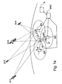
- FIG 1 shows, in a principle view, positioning by means of signals transmitted by four satellites SV1, SV2, SV3, SV4 and a reference receiver BS in a positioning receiver MS.
- the satellites transmit Ephemeris data and time data, on the basis of which the positioning receiver can make calculations to determine the position of the satellite at a time.
- These Ephemeris data and time data are transmitted in frames which are further divided into subframes.
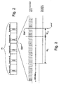
- Figure 2 shows an example of such a frame structure FR.
- each frame comprises 1500 bits which are divided into five subframes comprising 300 bits. Because the transmission of one bit takes 20 ms, the transmission of each subframe takes 6 s, and the whole frame is transmitted in 30 seconds.
- the subframes are numbered from 1 to 5.
- time data is transmitted, informing the moment of transmission of the subframe and information about the deviation of the satellite clock with respect to the time of the GPS system.
- Subframes 2 and 3 are used for the transmission of Ephemeris data.
- Subframe 4 contains other system information, such as universal time data (UTC, Universal Time, Coordinated).
- Subframe 5 is intended for the transmission of almanac data of all satellites.
- the unit of these subframes and frames is called a GPS navigation message which comprises 25 frames, i.e. 125 subframes. The length of the navigation message is thus 12 min 30 s.
- time is measured in seconds from the beginning of a week.
- the moment of beginning of a week is midnight between a Saturday and a Sunday.
- Each subframe to be transmitted contains information on the moment of the GPS week when the subframe was transmitted.
- the time data indicates the moment of transmission of a certain bit, i.e. in the GPS system, the moment of transmission of the last bit in the subframe.
- time is measured with high-precision atomic chronometers. In spite of this, the operation of each satellite is controlled in a control centre for the GPS system (not shown), and e . g . a time comparison is performed to detect chronometric errors in the satellites and to transmit this information to the satellite.
- N ms k the time, in milliseconds, passed since the reception of the last received bit
- N chip k the number (from 0 to 1022) of whole chips received after the change of the last epoch
- ⁇ chip k the measured code phase at the moment of positioning
- k the satellite index
- Fig. 3 illustrates this formula, and its different terms, used for estimating the moment of transmission of a signal received at a moment of positioning. It is obvious that Fig. 3 is simplified with respect to a real situation, because e.g. one code sequence comprises 1023 chips, wherein it is not reasonable to illustrate them precisely.
- the moment of positioning is illustrated by a dash and dot line which is indicated with the reference SM.
- a good constellation of satellites means that the satellites to be used for positioning are selected in such a way that, seen from the receiver, they are located in clearly different directions, that is, the solid angles in which the signals transmitted from different satellites enter the receiver, clearly differ from each other.
- the received information contained in the navigation message cannot necessarily be utilized.
- the only usable measurements to be performed for the carrier frequency signal are the number of chips and the code phase.
- the receiver has no proper Ephemeris data and no reference chronometer available, the position cannot be calculated solely on the basis of the number of the chips and the code phase.
- old Ephemeris data does not give a sufficiently precise position for satellites, wherein the precision of the positioning is impaired.
- the receiver has no navigation data available, which means that the calculation of signal transmission times according to formula (1) cannot be made and the positioning will fail.
- the document WO 99/19743 discloses a GPS receiver located at a base station of a cellular telephone network.
- the receiver determines the location of the base station and obtains GPS ephemeris and, if available, timing information.
- a server uses the obtained information to calculate auxiliary information for use by a GPS receiver.
- the base station transmits the auxiliary information to the GPS receiver which is located within a cellular telephone operating within the service area of the base station.
- the cellular telephone GPS receiver uses the auxiliary information to search for the code shift positions of all the appropriate codes within the signals coming from the GPS satellites.
- the pseudo ranges indicative of the geographical location of the cellular telephone are calculated from the code shift positions.
- the cellular telephone transmits the pseudo ranges to the cellular telephone network and the cellular telephone network calculates the geographical location of the cellular telephone.
- the cellular telephone determines its geographical location and transmits location information to the cellular telephone network.
- the document US-5,760,737 discloses a navigation system incorporating a method for detecting failures and determining an accuracy or error bound.
- the system has a receiver for receiving signals from several remote transmitters and a processor for determining a position solution from the signals.
- the processor employs Kalman filtering techniques, determines several position subsolutions from subsets of the signals, and computes covariance-based solution separation parameters based in statistical worst-case differences between the position solution and the subsolutions.
- the processor also computes error parameters defining statistical worst-case errors in each position subsolution. With the solution separation and the subsolution error parameters, the processor determines an error bound for the position solution.
- the invention is based on the idea that a communication network is used for positioning, such as a mobile communication network with which the positioning receiver communicates. Thus, it can be taken into account that the positioning receiver is in the vicinity of a certain access point, such as a base station. Furthermore, the location of this base station is known. Thus, this base station can be used to transmit information which is necessary in the positioning to the positioning receiver.
- the method according to the present invention is characterized in what will be presented in the characterizing part of the appended claim 1.
- the positioning apparatus according to the present invention is characterized in what will be presented in the characterizing part of the appended claim 14.
- the positioning apparatus according to the present invention is characterized in what will be presented in the characterizing part of the appended claim 26.
- the present invention can be used to achieve significant advantages when compared with methods and positioning devices of prior art.
- positioning can also be performed when navigation information cannot be received properly or at all.
- the effect of possible rounding-off errors on the positioning can be detected and corrected to correspond to the positioning.
- the algorithms required in the positioning are primarily run in a computing server communicating with a communication network, wherein the computing can be performed considerably faster than in solutions of prior art.
- a network-based implementation according to a preferred embodiment of the invention has still further advantages with respect to a network-aided receiver.
- the positioning computing is performed in a communication network instead of the receiver, the communication network does not need to transmit any assisting data to be used in the positioning, such as Ephemeris data, to the receiver.
- the reduced need of data transmission will also reduced the load on the communication network.
- the first positioning for example after turning on of a positioning receiver
- TTFF time to first fix
- the positioning receiver only needs to transmit the measured chip and code phase measurements to the computing server.
- the transmission of these measurement requires considerably fewer bits than the transmission of assisting data from the communication network to the positioning receiver.
- the positioning of the network-aided method can be delayed when the assisting data is delayed in the network.
- the positioning can be computed substantially immediately after the server has received the chip and code phase measurements from the positioning receiver. This is substantially advantageous. Particularly in emergency situations, the computed location of the receiver is substantially immediately known and one does not have to wait for it from the positioning receiver.
- the network-based implementation has the advantage that it is always possible to use the most recent Ephemeris data and possibly even DGPS corrections.
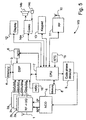
- a signal to be received via a first antenna 1 is converted preferably to an intermediate frequency or directly to a baseband frequency in converter blocks 2a-2d.
- the receiver MS of Fig. 5 comprises four receiving channels, each having a separate converter block 2a-2d, but it is obvious that there can be a different number of channels than is presented here.
- the signal, converted to the intermediate frequency or the baseband frequency in the converter blocks 2a-2d comprises two components, known as such: the I and Q components which have a phase difference of 90 degrees. These analog signal components, converted to the intermediate frequency, are digitized.
- the digitization at least one sample is taken of each chip in the signal components; that is, in the GPS system, at least 1,023,000 samples are taken in a second. Furthermore, the I and Q components of the digitized signal are multiplied with the signal formed by a first numerically controlled oscillator 5 (NCO). This signal of the first numerically controlled oscillator 5 is intended to correct a frequency deviation due to the Doppler effect or a frequency error in the local oscillator of the receiver (not shown).
- NCO numerically controlled oscillator 5
- This signal generated in the converter blocks 2a-2d are indicated in Fig. 5 with references G(a),I(a)-Q(d),I(d) are preferably led to a digital signal processing unit 3.
- Reference codes ref(k) corresponding to the codes used in the code modulation of the satellites to be received at a time are also generated in block 16.
- the receiver MS tends to use e.g. this reference code ref(k) to find out the code phase and frequency deviation of the signal of the satellite to be received on each receiving channel, to be used in operations after synchronization.
- a control block 7 is used to control e.g. a code phase detector 9, by means of which the frequency of the numerically controlled oscillator 5 is adjusted, when necessary.
- the synchronization is not discussed in more detail in this description, but it is prior art known as such.
- the digital signal processing unit 3 stores the navigation information preferably in a memory 4. In the method according to a first preferred embodiment of the present invention, this navigation information does not need to be detected and stored, but the positioning receiver MS must determine the chip and code phase of the signals received from the satellites.
- the positioning receiver MS also comprises means for performing the operations of a mobile station, such as a second antenna 10, a radio part 11, audio means, such as a codec 14a, a speaker 14b, and a microphone 14c, a display 12, and a keypad 13.
- a mobile station such as a second antenna 10, a radio part 11, audio means, such as a codec 14a, a speaker 14b, and a microphone 14c, a display 12, and a keypad 13.
- the determination of the chip and code phase is preferably performed substantially simultaneously for all the receiving channels, wherein the moment of receiving a signal is substantially the same on each receiving channel.
- the positioning receiver MS transmits the determined chip and code phase information of the satellites via the base station BS to the communication network preferably either after the determination, when the computing server requests for chip and code phase information, or upon initiation by a positioning command or the like, entered by the user.
- the computing server S When one wishes to perform positioning, it is examined preferably in the computing server S if the necessary navigation information is available in the computing server S. If there is no navigation information or it is insufficient, the computing server S preferably examines what required navigation information is not available in the computing server S at the time.
- the computing server S requests the positioning receiver MS to transmit the chip and code phase information. This can be performed e.g. in such a way that the computing server S transmits a request to the communication network, e.g. via a mobile switching center MSC to the base station, which transmits the request further to the positioning receiver MS.
- the computing server S requests the communication network to transmit the missing information.
- This information can be transmitted e.g. from a control center for the satellite positioning system (not shown).
- the moment of transmission of the received signals is preferably calculated on the basis of the formula 1. However, if there is not sufficiently navigation information received, in the method according to a preferred embodiment of the invention, the moment of transmission of the received signals is determined on the basis of the number N chip k and code phase ⁇ chip k of chips received after the change of the code phase of the received signal, as well as the navigation information in the computing server S.
- the position can be calculated by several different methods, but only one method is presented herein: the method of least mean squares (LMS).
- LMS least mean squares
- some basic operations, such as removal of satellite SV1, SV2, SV3, SV4 clock bias, ionosphere correction, etc. are disregarded in this context.
- previous positioning data is not available in the receiver and that all measurements are performed at the same moment, i.e. sampling is performed parallelly at the same moment on each receiving channel.
- the received signals are stored in a memory, wherein their further processing can be performed at different times.
- a reference clock 15 is relatively accurate and frequency stable.
- This reference clock is formed by e.g. the real-time clock (RTC) of the receiver MS, or it can also be formed by an external clock (not shown), or the time data can be obtained from an external network, such as the mobile communication network.
- RTC real-time clock
- the determination of the transmission time ToT comprises five elements, of which only the last two, i.e. the number N chip k and code phase ⁇ chip k of chips received after the change of the code phase can be determined in a situation in which the strength of the signal to be received is low.
- One millisecond in time means a distance of about 300 km the signal propagating substantially at the speed of light.
- the differences in milliseconds on the different receiving channels must be determined on the basis of the distances between the satellites SV1, SV2, SV3, SV4 and the receiver MS.
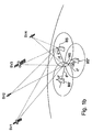
- the estimated position of the receiver MS is not necessarily known. Instead, in the system of Figs. 1a and 1b , the position of the receiver MS can be estimated by means of the position of a selected reference point, such as a base station BS.
- a selected reference point such as a base station BS.
- the distance between a mobile station and the base station with which the mobile station communicates at a time is normally not more than about 30 km.
- the receiver MS is within this radius of 30 km from the location of the base station BS.
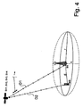
- the propagation time of the signal transmitted by a satellite to the base station (indicated with reference D1 in Fig. 4 ) and the propagation time from the satellite to the positioning receiver (indicated with reference D2 in Fig. 4 ) differ not more than about 100 ⁇ s.
- the distance between the positioning receiver MS and the base station BS does not change significantly in the range of the base station BS, wherein it can be assumed that there is a difference of less than one millisecond in the moments of receiving the signal of the same satellite in the positioning receiver and in the base station BS. This is illustrated in the appended Fig. 4 .
- T ⁇ ToT k T GPS - N ⁇ ms k - N chip k - ⁇ ⁇ chip k
- the measured value of the moment of transmission of the signal from any satellite can be selected as the reference time.
- the satellite time at the moment of receiving the signal i.e. the GPS time, T ⁇ GPS
- T ⁇ GPS the satellite time at the moment of receiving the signal
- T ⁇ GPS the transmission delay
- An estimate normally used for the transmission delay is 70 ms.
- T ⁇ GPS T ⁇ ToT k + 0.070
- the estimated pseudoranges are calculated with respect to the position x ⁇ ⁇ u of the receiver of the user as well as to the positions x ⁇ SV k ( T ⁇ GPS ) of the satellites at the estimated moment of transmission ToT.
- the user's default position is selected the position of the base station BS with which the mobile station communicates at the time.
- the positions of the satellites are calculated as a function of time by means of equations known as such.
- the term t indicates a (strongly) non-linear function
- the subindex p indicates that it is an estimate in question
- x ⁇ ⁇ u is the estimated position of the user, in which the line above the variable indicates that it is a vector.
- the aim is to find a position data x ⁇ ⁇ u and a time error t u that are most suitable for M number of measurements.
- M ⁇ ⁇ x ⁇ ⁇ u is a position correction vector, ⁇ t u is time error correction, and H is the linearized Jacobian matrix of estimated pseudoranges at point x ⁇ ⁇ u .
- SSE sum of squared errors
- the brackets indicate that the term is based on the parameter presented in the brackets. Using such a presentation, it can be clearly seen that the measured pseudoranges are functions of true GPS time, the rest being functions of estimated GPS time. Thus, it is possible to calculate the time difference between the estimated GPS time and the true GPS time on the basis of the measurements, and thus it is also possible to synchronize the receiver with the real GPS time.
- this time difference can be utilized in the computing server S to correct the estimated GPS time, after which it is possible to recalculate the positions of the satellites to obtain better positioning particularly in a situation in which the calculated time difference was significantly great.
- the calculation of the distance may in some cases cause rounding-off errors. For example, if the calculated distance in milliseconds before rounding off is close to the next integer and the receiver MS is close to the base station BS, this may result in an error of almost one millisecond. This may cause an error of even 300 km in the calculation of the distance between the receiver and the satellite, which will distort the positioning of the receiver to a significant extent. In some cases, this error can be detected in the height data calculated for the position of the receiver, which indicates that the receiver is at a height of tens of kilometres or deep down in the earth. Thus, the error can be easily detected. However, this is not always the case.
- the method according to a preferred embodiment of the invention utilizes the information that the receiver MS is close to the base station BS whose position is known at a sufficient accuracy.
- This limit is, in the direction of the earth surface, for example a circle with its centre at the base station and having a radius of about 30 km.
- suitable limit values can be set in the height direction. If the calculation yields position data for the receiver MS which is outside said limits, it can be assumed that an error has been caused by rounding off. After this, it is determined in the computing server S, at which satellite/ satellites this error has occurred. This can be performed by examining the remainders of the values calculated with the formula 2.
- This method can be used to quickly detect possible errors caused by rounding off and to perform the necessary correction operations.
- Another method to detect rounding-off errors is to examine error values calculated with the formula 9, and if any value is clearly different from the other values (significantly higher), an error has been probably caused by rounding-off in the calculation of the distance of the satellite corresponding to the value.
- the positioning information can be transmitted to the positioning receiver MS, in which the position can be displayed to the user.
- the positioning information is substantially immediately available in the communication network, e.g. at the mobile switching center MSC, even though this information were not transmitted to the positioning receiver. This will speed up the forwarding of aid to the correct location.
- the receiver MS is thus primarily to measure the signals of the satellites and in some cases to preprocess them. After this, the receiver MS transmits the signals to the computing server S to calculate the actual position.
- the receiver MS comprises, in a minimum, of only the equipment required for taking the chip and code phase measurements and for transmitting them via the network to the server. In this case, the receiver MS does not necessarily need even time data.
- the computing required in the positioning is performed in the positioning receiver MS.
- the most substantial differences to the method according to the first preferred embodiment of the invention is that e.g. the GPS time data and the Ephemeris data are transmitted to the positioning receiver MS instead of the computing server S.
- the digital signal processing unit 3 stores the navigation information preferably in a memory 4.
- the detection and storage are preferably performed substantially simultaneously for all the receiving channels, wherein the moment of receiving the signal received is substantially the same on each receiving channel.
- it is examined preferably in the digital signal processing unit 3, if the necessary navigation information has been received If there is sufficient navigation information stored in the memory 5, the moment of the transmission of the received signals is preferably calculated on the basis of the formula 1.
- the moment of transmission of the received signals is determined on the basis of the number N chip k and code phase ⁇ chip k of chips received after the change of the code phase of the received signal, as well as the navigation information transmitted via the base station and received in the positioning receiver MS, as has been described above in connection with the description of the first preferred embodiment of the method according to the invention.
- the reference chronometer to be used in the receiver MS is accurate.
- the accuracy of the real-time clock RTC of the receiver may vary.
- the time data to be transmitted from the base station BS of the mobile communication network and to be received at the receiver MS can be delayed to a significant extent.
- this delay is not known to the receiver and, moreover, the delay may vary at different times of transmission of the time data.
- the receiver if the receiver is not capable of decoding the information transmitted in the navigation message, the receiver cannot obtain information about the GPS time. An incorrect GPS time estimate may cause even significant errors in the positioning. Effects and elimination of the GPS time data are described in more detail in a parallel patent application by the applicant, which is incorporated herein by reference.
- a base station BS was used as a reference point; however, it is obvious that also another point whose location is known with some accuracy can be selected as the reference point. Thus, this reference point is used as a default position for the receiver in the positioning.
- the invention can also be applied in such a system which utilizes e.g. a mobile communication system in addition with positioning by means of satellites. It is thus possible to use three or more base stations BS, BS', BS" of a mobile communication system, whose locations are known, to determine the position of a receiver MS at an accuracy which is typically slightly poorer than GPS positioning, by using propagation time measurement functions of the mobile communication system to determine the propagation time of a signal from the base station to the receiver. By means of the propagation time measurements, it is possible to determine the distance of the receiver MS from the different base stations in time, wherein the position of the mobile station MS can be determined.
- AOA angles of arrival
- Yet another alternative is, for example, to determine both the propagation time and the angle of arrival ⁇ , ⁇ ', ⁇ " of the signal from the mobile station to at least one base station BS, BS', BS" and to transmit these determined propagation time and angle of arrival data to a computing device, such as a computing server S or the receiver MS.
- a computing device such as a computing server S or the receiver MS.
- This arrangement can be utilized for example when it is not possible to receive a signal transmitted by satellites at the receiver MS, or the signal strength is so low that measurements cannot be made on the chip level.
- the reference point to be selected can be e . g . the position of the receiver MS determined on the basis of said base stations.
- the application software of the computing server S is provided with the necessary program commands in a way known as such.
- the computing server S can be arranged e.g. in connection with a mobile switching center MSC, wherein data transmission between the communication network, in this case a mobile communication network, and the computing server S is performed via the mobile switching center MSC. It is obvious that the computing server S can also be coupled to communicate with the communication network in a way known as such.
- the calculations presented above are preferably performed in the digital signal processing unit 3 and/or in the control block 7.
- the application software is provided with the necessary program commands in a way known as such.
- the results of the calculations, and possible intermediate results needed, are stored in a memory 4, 8.
- the determined position of the positioning receiver can be preferably displayed on the display 12 e.g. in coordinate format.
- map information on the area in which the user's positioning receiver MS is located at the time can be displayed on the display 12. This map information can be loaded i.e.
- the mobile communication network preferably in such a way that the determined location data are transmitted from the mobile station functions of the positioning receiver MS to the base station BS which transmits them further for processing, e.g. to a mobile switching centre (not shown).
- the mobile communication network contacts, i.e. via the Internet network, a server (not shown) containing map information of the area in question. After this, the map information is transmitted via the mobile communication network to the base station BS and further to the positioning receiver MS.
- these means for positioning the electronic device comprise a positioning receiver MS according to a preferred embodiment of the invention.
- the invention can also be applied in connection with other wireless data transmission networks than mobile communication networks.
- the location of a known point in the vicinity of the positioning receiver can be received via the wireless data transmission network.
Priority Applications (1)
| Application Number | Priority Date | Filing Date | Title |
|---|---|---|---|
| EP08159680.1A EP2003469B1 (en) | 2000-01-04 | 2000-12-21 | A method for performing positioning and an electronic device |
Applications Claiming Priority (4)
| Application Number | Priority Date | Filing Date | Title |
|---|---|---|---|
| FI20000017 | 2000-01-04 | ||
| FI20000017A FI20000017A0 (fi) | 2000-01-04 | 2000-01-04 | Menetelmä sijainnin määrityksen suorittamiseksi ja elektroniikkalaite |
| FI20000139A FI108895B (fi) | 2000-01-04 | 2000-01-24 | Menetelmä sijainnin määrityksen suorittamiseksi ja elektroniikkalaite |
| FI20000139 | 2000-01-24 |
Related Child Applications (1)
| Application Number | Title | Priority Date | Filing Date |
|---|---|---|---|
| EP08159680.1A Division EP2003469B1 (en) | 2000-01-04 | 2000-12-21 | A method for performing positioning and an electronic device |
Publications (3)
| Publication Number | Publication Date |
|---|---|
| EP1115009A2 EP1115009A2 (en) | 2001-07-11 |
| EP1115009A3 EP1115009A3 (en) | 2004-02-04 |
| EP1115009B1 true EP1115009B1 (en) | 2008-08-27 |
Family
ID=26160920
Family Applications (2)
| Application Number | Title | Priority Date | Filing Date |
|---|---|---|---|
| EP08159680.1A Expired - Lifetime EP2003469B1 (en) | 2000-01-04 | 2000-12-21 | A method for performing positioning and an electronic device |
| EP00660240A Expired - Lifetime EP1115009B1 (en) | 2000-01-04 | 2000-12-21 | A method for performing positioning and an electronic device |
Family Applications Before (1)
| Application Number | Title | Priority Date | Filing Date |
|---|---|---|---|
| EP08159680.1A Expired - Lifetime EP2003469B1 (en) | 2000-01-04 | 2000-12-21 | A method for performing positioning and an electronic device |
Country Status (6)
| Country | Link |
|---|---|
| EP (2) | EP2003469B1 (fi) |
| JP (2) | JP5536295B2 (fi) |
| AT (1) | ATE406584T1 (fi) |
| DE (1) | DE60040053D1 (fi) |
| ES (1) | ES2312330T3 (fi) |
| FI (1) | FI108895B (fi) |
Families Citing this family (5)
| Publication number | Priority date | Publication date | Assignee | Title |
|---|---|---|---|---|
| JP4609095B2 (ja) * | 2005-02-04 | 2011-01-12 | セイコーエプソン株式会社 | 測位システム |
| US7671790B2 (en) * | 2006-07-20 | 2010-03-02 | Seiko Epson Corporation | Positioning system, positioning device, communication base station, control method, and recording medium storing program |
| US8059028B2 (en) * | 2008-08-14 | 2011-11-15 | Trueposition, Inc. | Hybrid GNSS and TDOA wireless location system |
| WO2009079380A2 (en) * | 2007-12-14 | 2009-06-25 | Magellan Systems Japan, Inc. | Process for sub-microsecond time transfer using weak gps/gnss signals |
| EP3139193A1 (en) * | 2012-06-05 | 2017-03-08 | NextNav, LLC | Systems and methods for location positioning of user device |
Family Cites Families (8)
| Publication number | Priority date | Publication date | Assignee | Title |
|---|---|---|---|---|
| JPS62163987A (ja) * | 1986-01-16 | 1987-07-20 | Hitachi Ltd | 測位装置 |
| US5917444A (en) * | 1995-05-22 | 1999-06-29 | Trimble Navigation Ltd. | Reduction of time to first fix in an SATPS receiver |
| JPH09288165A (ja) * | 1996-04-23 | 1997-11-04 | Matsushita Electric Works Ltd | Gps受信機 |
| US5760737A (en) * | 1996-09-11 | 1998-06-02 | Honeywell Inc. | Navigation system with solution separation apparatus for detecting accuracy failures |
| US6215441B1 (en) * | 1997-04-15 | 2001-04-10 | Snaptrack, Inc. | Satellite positioning reference system and method |
| US6118977A (en) * | 1997-09-11 | 2000-09-12 | Lucent Technologies, Inc. | Telecommunications-assisted satellite positioning system |
| US6070078A (en) * | 1997-10-15 | 2000-05-30 | Ericsson Inc. | Reduced global positioning system receiver code shift search space for a cellular telephone system |
| US5999124A (en) * | 1998-04-22 | 1999-12-07 | Snaptrack, Inc, | Satellite positioning system augmentation with wireless communication signals |
-
2000
- 2000-01-24 FI FI20000139A patent/FI108895B/fi not_active IP Right Cessation
- 2000-12-21 ES ES00660240T patent/ES2312330T3/es not_active Expired - Lifetime
- 2000-12-21 DE DE60040053T patent/DE60040053D1/de not_active Expired - Lifetime
- 2000-12-21 EP EP08159680.1A patent/EP2003469B1/en not_active Expired - Lifetime
- 2000-12-21 EP EP00660240A patent/EP1115009B1/en not_active Expired - Lifetime
- 2000-12-21 AT AT00660240T patent/ATE406584T1/de active
-
2001
- 2001-01-04 JP JP2001000230A patent/JP5536295B2/ja not_active Expired - Fee Related
-
2012
- 2012-12-28 JP JP2012287613A patent/JP2013127470A/ja active Pending
Also Published As
| Publication number | Publication date |
|---|---|
| JP2001215270A (ja) | 2001-08-10 |
| FI20000139A0 (fi) | 2000-01-24 |
| EP2003469B1 (en) | 2019-07-24 |
| FI20000139A (fi) | 2001-07-05 |
| EP1115009A2 (en) | 2001-07-11 |
| EP2003469A3 (en) | 2010-06-23 |
| FI108895B (fi) | 2002-04-15 |
| JP5536295B2 (ja) | 2014-07-02 |
| EP1115009A3 (en) | 2004-02-04 |
| JP2013127470A (ja) | 2013-06-27 |
| EP2003469A2 (en) | 2008-12-17 |
| ATE406584T1 (de) | 2008-09-15 |
| DE60040053D1 (de) | 2008-10-09 |
| ES2312330T3 (es) | 2009-03-01 |
Similar Documents
| Publication | Publication Date | Title |
|---|---|---|
| US6476762B2 (en) | Method for performing positioning and an electronic device | |
| EP1115008B1 (en) | A method for determining reference time error and an electronic device | |
| US6671620B1 (en) | Method and apparatus for determining global position using almanac information | |
| EP1237009B1 (en) | A method for positioning, a positioning system, and a mobile device | |
| US6570533B2 (en) | Method for determining the phase of information, and an electronic device | |
| US6771215B2 (en) | Determination of the transmission time of a signal part in a positioning system | |
| US6583759B2 (en) | Method for determining a position, a positioning system, and an electronic device | |
| EP1528404B1 (en) | Method and apparatus for creating acquisition assistance information in assisted global positioning system | |
| EP2069817B1 (en) | A method and system for all-in-view coherent gps signal prn codes acquisition and navigation solution determination | |
| JP2013127470A (ja) | 受信機を測位する方法、測位システム及び電子装置 | |
| US6784834B2 (en) | Method for performing positioning and an electronic device | |
| EP1229341B1 (en) | A method for defining the error of reference time and an electronic device | |
| EP1154282B1 (en) | A method for determining the position of an object, a mobile receiver and a positioning system | |
| US6882306B2 (en) | Method for determining a position of an electronic device using a satellite positioning system | |
| FI111482B (fi) | Menetelmä sijainninmäärityksen suorittamiseksi ja elektroniikkalaite | |
| KR20060111689A (ko) | 이동 단말기의 위성 기반 위치 확인 |
Legal Events
| Date | Code | Title | Description |
|---|---|---|---|
| PUAI | Public reference made under article 153(3) epc to a published international application that has entered the european phase |
Free format text: ORIGINAL CODE: 0009012 |
|
| AK | Designated contracting states |
Kind code of ref document: A2 Designated state(s): AT BE CH CY DE DK ES FI FR GB GR IE IT LI LU MC NL PT SE TR |
|
| AX | Request for extension of the european patent |
Free format text: AL;LT;LV;MK;RO;SI |
|
| RAP1 | Party data changed (applicant data changed or rights of an application transferred) |
Owner name: NOKIA CORPORATION |
|
| PUAL | Search report despatched |
Free format text: ORIGINAL CODE: 0009013 |
|
| AK | Designated contracting states |
Kind code of ref document: A3 Designated state(s): AT BE CH CY DE DK ES FI FR GB GR IE IT LI LU MC NL PT SE TR |
|
| AX | Request for extension of the european patent |
Extension state: AL LT LV MK RO SI |
|
| 17P | Request for examination filed |
Effective date: 20040712 |
|
| 17Q | First examination report despatched |
Effective date: 20040817 |
|
| AKX | Designation fees paid |
Designated state(s): AT BE CH CY DE DK ES FI FR GB GR IE IT LI LU MC NL PT SE TR |
|
| GRAP | Despatch of communication of intention to grant a patent |
Free format text: ORIGINAL CODE: EPIDOSNIGR1 |
|
| GRAS | Grant fee paid |
Free format text: ORIGINAL CODE: EPIDOSNIGR3 |
|
| GRAA | (expected) grant |
Free format text: ORIGINAL CODE: 0009210 |
|
| STAA | Information on the status of an ep patent application or granted ep patent |
Free format text: STATUS: THE PATENT HAS BEEN GRANTED |
|
| AK | Designated contracting states |
Kind code of ref document: B1 Designated state(s): AT BE CH CY DE DK ES FI FR GB GR IE IT LI LU MC NL PT SE TR |
|
| REG | Reference to a national code |
Ref country code: GB Ref legal event code: FG4D |
|
| REG | Reference to a national code |
Ref country code: CH Ref legal event code: EP |
|
| REG | Reference to a national code |
Ref country code: IE Ref legal event code: FG4D |
|
| REF | Corresponds to: |
Ref document number: 60040053 Country of ref document: DE Date of ref document: 20081009 Kind code of ref document: P |
|
| PG25 | Lapsed in a contracting state [announced via postgrant information from national office to epo] |
Ref country code: FI Free format text: LAPSE BECAUSE OF FAILURE TO SUBMIT A TRANSLATION OF THE DESCRIPTION OR TO PAY THE FEE WITHIN THE PRESCRIBED TIME-LIMIT Effective date: 20080827 |
|
| REG | Reference to a national code |
Ref country code: ES Ref legal event code: FG2A Ref document number: 2312330 Country of ref document: ES Kind code of ref document: T3 |
|
| PG25 | Lapsed in a contracting state [announced via postgrant information from national office to epo] |
Ref country code: DK Free format text: LAPSE BECAUSE OF FAILURE TO SUBMIT A TRANSLATION OF THE DESCRIPTION OR TO PAY THE FEE WITHIN THE PRESCRIBED TIME-LIMIT Effective date: 20080827 |
|
| PG25 | Lapsed in a contracting state [announced via postgrant information from national office to epo] |
Ref country code: PT Free format text: LAPSE BECAUSE OF FAILURE TO SUBMIT A TRANSLATION OF THE DESCRIPTION OR TO PAY THE FEE WITHIN THE PRESCRIBED TIME-LIMIT Effective date: 20090127 |
|
| PLBE | No opposition filed within time limit |
Free format text: ORIGINAL CODE: 0009261 |
|
| STAA | Information on the status of an ep patent application or granted ep patent |
Free format text: STATUS: NO OPPOSITION FILED WITHIN TIME LIMIT |
|
| PG25 | Lapsed in a contracting state [announced via postgrant information from national office to epo] |
Ref country code: MC Free format text: LAPSE BECAUSE OF NON-PAYMENT OF DUE FEES Effective date: 20081231 |
|
| REG | Reference to a national code |
Ref country code: CH Ref legal event code: PL |
|
| 26N | No opposition filed |
Effective date: 20090528 |
|
| PG25 | Lapsed in a contracting state [announced via postgrant information from national office to epo] |
Ref country code: IT Free format text: LAPSE BECAUSE OF FAILURE TO SUBMIT A TRANSLATION OF THE DESCRIPTION OR TO PAY THE FEE WITHIN THE PRESCRIBED TIME-LIMIT Effective date: 20080827 |
|
| NLV4 | Nl: lapsed or anulled due to non-payment of the annual fee |
Effective date: 20090701 |
|
| PG25 | Lapsed in a contracting state [announced via postgrant information from national office to epo] |
Ref country code: LI Free format text: LAPSE BECAUSE OF NON-PAYMENT OF DUE FEES Effective date: 20081231 Ref country code: IE Free format text: LAPSE BECAUSE OF NON-PAYMENT OF DUE FEES Effective date: 20081221 Ref country code: CH Free format text: LAPSE BECAUSE OF NON-PAYMENT OF DUE FEES Effective date: 20081231 |
|
| PG25 | Lapsed in a contracting state [announced via postgrant information from national office to epo] |
Ref country code: NL Free format text: LAPSE BECAUSE OF NON-PAYMENT OF DUE FEES Effective date: 20090701 |
|
| PG25 | Lapsed in a contracting state [announced via postgrant information from national office to epo] |
Ref country code: SE Free format text: LAPSE BECAUSE OF FAILURE TO SUBMIT A TRANSLATION OF THE DESCRIPTION OR TO PAY THE FEE WITHIN THE PRESCRIBED TIME-LIMIT Effective date: 20081127 |
|
| REG | Reference to a national code |
Ref country code: NL Ref legal event code: RDX Effective date: 20100602 Ref country code: NL Ref legal event code: RD1H Effective date: 20090922 |
|
| PG25 | Lapsed in a contracting state [announced via postgrant information from national office to epo] |
Ref country code: LU Free format text: LAPSE BECAUSE OF NON-PAYMENT OF DUE FEES Effective date: 20081221 |
|
| PG25 | Lapsed in a contracting state [announced via postgrant information from national office to epo] |
Ref country code: CY Free format text: LAPSE BECAUSE OF FAILURE TO SUBMIT A TRANSLATION OF THE DESCRIPTION OR TO PAY THE FEE WITHIN THE PRESCRIBED TIME-LIMIT Effective date: 20080827 |
|
| PG25 | Lapsed in a contracting state [announced via postgrant information from national office to epo] |
Ref country code: TR Free format text: LAPSE BECAUSE OF FAILURE TO SUBMIT A TRANSLATION OF THE DESCRIPTION OR TO PAY THE FEE WITHIN THE PRESCRIBED TIME-LIMIT Effective date: 20080827 |
|
| PG25 | Lapsed in a contracting state [announced via postgrant information from national office to epo] |
Ref country code: GR Free format text: LAPSE BECAUSE OF FAILURE TO SUBMIT A TRANSLATION OF THE DESCRIPTION OR TO PAY THE FEE WITHIN THE PRESCRIBED TIME-LIMIT Effective date: 20081128 |
|
| REG | Reference to a national code |
Ref country code: NL Ref legal event code: RDX Effective date: 20100602 Ref country code: NL Ref legal event code: RD2A Effective date: 20101123 Ref country code: NL Ref legal event code: RD1H Effective date: 20090922 |
|
| REG | Reference to a national code |
Ref country code: NL Ref legal event code: RD1B Effective date: 20101231 |
|
| REG | Reference to a national code |
Ref country code: NL Ref legal event code: RD2A Effective date: 20120120 |
|
| REG | Reference to a national code |
Ref country code: GB Ref legal event code: 732E Free format text: REGISTERED BETWEEN 20150910 AND 20150916 |
|
| REG | Reference to a national code |
Ref country code: DE Ref legal event code: R082 Ref document number: 60040053 Country of ref document: DE Representative=s name: COHAUSZ & FLORACK PATENT- UND RECHTSANWAELTE P, DE Ref country code: DE Ref legal event code: R081 Ref document number: 60040053 Country of ref document: DE Owner name: NOKIA TECHNOLOGIES OY, FI Free format text: FORMER OWNER: NOKIA CORP., 02610 ESPOO, FI |
|
| REG | Reference to a national code |
Ref country code: FR Ref legal event code: PLFP Year of fee payment: 16 |
|
| REG | Reference to a national code |
Ref country code: ES Ref legal event code: PC2A Owner name: NOKIA TECHNOLOGIES OY Effective date: 20151124 |
|
| REG | Reference to a national code |
Ref country code: AT Ref legal event code: PC Ref document number: 406584 Country of ref document: AT Kind code of ref document: T Owner name: NOKIA TECHNOLOGIES OY, FI Effective date: 20160104 |
|
| REG | Reference to a national code |
Ref country code: FR Ref legal event code: PLFP Year of fee payment: 17 |
|
| REG | Reference to a national code |
Ref country code: FR Ref legal event code: TP Owner name: NOKIA TECHNOLOGIES OY, FI Effective date: 20170109 |
|
| REG | Reference to a national code |
Ref country code: FR Ref legal event code: PLFP Year of fee payment: 18 |
|
| PGFP | Annual fee paid to national office [announced via postgrant information from national office to epo] |
Ref country code: DE Payment date: 20191210 Year of fee payment: 20 |
|
| PGFP | Annual fee paid to national office [announced via postgrant information from national office to epo] |
Ref country code: FR Payment date: 20191114 Year of fee payment: 20 Ref country code: BE Payment date: 20191118 Year of fee payment: 20 |
|
| PGFP | Annual fee paid to national office [announced via postgrant information from national office to epo] |
Ref country code: AT Payment date: 20191125 Year of fee payment: 20 |
|
| PGFP | Annual fee paid to national office [announced via postgrant information from national office to epo] |
Ref country code: ES Payment date: 20200102 Year of fee payment: 20 Ref country code: GB Payment date: 20191219 Year of fee payment: 20 |
|
| REG | Reference to a national code |
Ref country code: DE Ref legal event code: R071 Ref document number: 60040053 Country of ref document: DE |
|
| REG | Reference to a national code |
Ref country code: GB Ref legal event code: PE20 Expiry date: 20201220 |
|
| PG25 | Lapsed in a contracting state [announced via postgrant information from national office to epo] |
Ref country code: GB Free format text: LAPSE BECAUSE OF EXPIRATION OF PROTECTION Effective date: 20201220 |
|
| REG | Reference to a national code |
Ref country code: BE Ref legal event code: MK Effective date: 20201221 |
|
| REG | Reference to a national code |
Ref country code: AT Ref legal event code: MK07 Ref document number: 406584 Country of ref document: AT Kind code of ref document: T Effective date: 20201221 |
|
| REG | Reference to a national code |
Ref country code: ES Ref legal event code: FD2A Effective date: 20210326 |
|
| PG25 | Lapsed in a contracting state [announced via postgrant information from national office to epo] |
Ref country code: ES Free format text: LAPSE BECAUSE OF EXPIRATION OF PROTECTION Effective date: 20201222 |