EP1114992A2 - Device and method for hydrogen collection and detection - Google Patents
Device and method for hydrogen collection and detection Download PDFInfo
- Publication number
- EP1114992A2 EP1114992A2 EP00311501A EP00311501A EP1114992A2 EP 1114992 A2 EP1114992 A2 EP 1114992A2 EP 00311501 A EP00311501 A EP 00311501A EP 00311501 A EP00311501 A EP 00311501A EP 1114992 A2 EP1114992 A2 EP 1114992A2
- Authority
- EP
- European Patent Office
- Prior art keywords
- plate
- hydrogen
- collector plate
- collector
- steel
- Prior art date
- Legal status (The legal status is an assumption and is not a legal conclusion. Google has not performed a legal analysis and makes no representation as to the accuracy of the status listed.)
- Granted
Links
Images


Classifications
-
- G—PHYSICS
- G01—MEASURING; TESTING
- G01N—INVESTIGATING OR ANALYSING MATERIALS BY DETERMINING THEIR CHEMICAL OR PHYSICAL PROPERTIES
- G01N1/00—Sampling; Preparing specimens for investigation
- G01N1/02—Devices for withdrawing samples
- G01N1/22—Devices for withdrawing samples in the gaseous state
- G01N1/24—Suction devices
-
- G—PHYSICS
- G01—MEASURING; TESTING
- G01N—INVESTIGATING OR ANALYSING MATERIALS BY DETERMINING THEIR CHEMICAL OR PHYSICAL PROPERTIES
- G01N33/00—Investigating or analysing materials by specific methods not covered by groups G01N1/00 - G01N31/00
- G01N33/0004—Gaseous mixtures, e.g. polluted air
- G01N33/0009—General constructional details of gas analysers, e.g. portable test equipment
- G01N33/0027—General constructional details of gas analysers, e.g. portable test equipment concerning the detector
- G01N33/0036—General constructional details of gas analysers, e.g. portable test equipment concerning the detector specially adapted to detect a particular component
- G01N33/005—H2
-
- G—PHYSICS
- G01—MEASURING; TESTING
- G01N—INVESTIGATING OR ANALYSING MATERIALS BY DETERMINING THEIR CHEMICAL OR PHYSICAL PROPERTIES
- G01N33/00—Investigating or analysing materials by specific methods not covered by groups G01N1/00 - G01N31/00
- G01N33/20—Metals
- G01N33/202—Constituents thereof
- G01N33/2022—Non-metallic constituents
- G01N33/2025—Gaseous constituents
-
- G—PHYSICS
- G01—MEASURING; TESTING
- G01N—INVESTIGATING OR ANALYSING MATERIALS BY DETERMINING THEIR CHEMICAL OR PHYSICAL PROPERTIES
- G01N1/00—Sampling; Preparing specimens for investigation
- G01N1/28—Preparing specimens for investigation including physical details of (bio-)chemical methods covered elsewhere, e.g. G01N33/50, C12Q
- G01N1/38—Diluting, dispersing or mixing samples
Definitions
- This invention is concerned with hydrogen collection and detection. More specifically, the invention relates to the examination of iron and steel (and perhaps other materials) to determine whether they are giving off hydrogen gas, and so may be at risk from such problems as hydrogen embrittlement, and to devices for use in such an examination.
- Hydrogen is often inadvertently introduced to steel at high temperatures, such as in a melt, or during welding in a damp atmosphere.
- the solubility of hydrogen in steel increases with temperature, so these processes may result in supersaturation of hydrogen when the metal cools.
- Supersaturation of hydrogen in steel may also occur upon corrosion, electroplating, and other surface treatments, or upon exposure of the steel surface to hydrogen sulphide (H2S; sour gas, as often found in oil deposits, and thus in the pipelines carrying the oil and its derivatives elsewhere).
- H2S hydrogen sulphide
- chemical reactions effected on an industrial scale are often carried out in steel vessels and pipework, and those that involve hydrogen and high temperatures and pressures, such as the hydrogenation of alkenes, can result in deleterious hydrogen absorption by the steel.
- the enclosure - hereinafter referred to as the "collector" - is pressed against the surface from which hydrogen is thought to be emanating, and carrier gas is then drawn into the formed closed volume, and, taking any hydrogen with it, is passed on to the actual hydrogen detector apparatus.
- the present invention also concerns such a hydrogen collection and detection system, likewise employing a carrier gas, preferably ambient air, to collect within an enclosure hydrogen emanating from the test surface, and convey it to some remote hydrogen gas sensor.
- a carrier gas preferably ambient air
- the present invention relates specifically to the physical nature of the collector, and to the manner in which it can conveniently be attached to the test surface even when that surface is of a non-planar form.
- hydrogen may emanate from a steel (say) surface only in localised 'hotspots', and it may emanate over infrequent and unpredictable periods of time.
- a steel (say) surface For example, in gas pipelines conveying oil volatiles, sour gas and water, hydrogen entry may be confined to 'puddles' of water at the base of the pipe's interior. Eventually this hydrogen will exit at the pipe's exterior face, but that may not be until after a delay of several days (indeed, the delay may vary - for example, in consequence of variable composition of the interior gas - over a timescale ranging from days to years).
- an occasional weld may contain significant diffusible hydrogen due to a damp weld consumable.
- hydrogen may have been introduced into a cast steel only from an occasional batch of molten steel which contained dissolved hydrogen sourced from one particular feedstock ingredient. It is therefore frequently necessary to carry out multiple tests on steel surfaces in the search for a prospective hydrogen flux, over a period of time, or over a range of surfaces.
- These steel surfaces may be of variable surface geometry either on account of unpredictable factors, as is the case with steel plate that is milled to a flatness tolerance of no better than a few millimetres per metre length, or due to predictable factors, as is the case with steel pipes in a production plant whose diameters commonly vary by as much as from 10 to 100cm.
- any hydrogen flux measurement must be reproducible.
- intermittent testing for flux from a pipe surface over several months may only provide an insight into progressive enhancement or attenuation of hydrogen entry at the pipe's interior if the measurements are comparable - in other words, if they provide effective monitoring of the hydrogen flux over significantly long time periods.
- the present invention seeks first to deal with the conformity problem - having the collector flexible enough to "fit" the surface to which it is applied regardless, within reason, of how much or little it is curved. More particularly, to render the collector conformable to surfaces of moderate curvature the invention proposes making it as a flexible (and preferably an elastically-flexible) plate on the receptor face of which are constructed raised grooves or high spots, which may be presented approximately parallel to an approximately flat surface or approximately tangential to a curved surface, and which form guiding channels along which hydrogen emanating from the surface underlying the plate can be drawn and sent to the detector system.
- this invention provides, for use as the collector of a hydrogen collection and detection system, a flexible plate on the receptor face of which are constructed guide channels along which in use hydrogen emanating from the surface underlying the plate can be drawn and sent to the associated detector system.
- the invention also provides such a collector plate that can be used to form the enclosure the subject of the aforementioned Patent, and which therefore has input means for receiving a carrier gas and output means for delivering the resultant mixture of carrier gas and emanated hydrogen, and which is operatively connected to a hydrogen detector for reception of the mixture of carrier gas and emanated hydrogen collected thereby and for the detection and measurement thereof.
- the collector of this invention is a flexible plate.
- the plate material can be any that is sufficiently flexible - and, in particular, elastically (rather than plasticly) flexible, so that it will recover its own, basic, shape without the need for any intervention - to allow the plate to bend to the shape of the surface against which it is to be used but which will not allow the collected hydrogen to diffuse therethrough (and so be lost before it can be detected and measured).
- the plate body (as distinct from the high spots defining the channel) is most preferably made of a metal, a metallised plastic, or a plastic/metal laminate.
- “Bare” elastomeric plastics some of which are highly elastically deformable, have been tested, but are generally found to be too permeable to hydrogen, so reducing the effective hydrogen capture area significantly, and hence raising the minimum flux detection threshold. Even if a plastic were found for which the hydrogen permeability were adequately low in this regard, significant outgassing of hydrogen might occur in a second test subsequent to permeation of hydrogen into the plastic in a first test (for instance, this might happen immediately following a test on a surface zone of high emanating flux) such that during a test at another site of zero flux sufficient from the plastic could be entrained into the gas stream to give rise to a false indication of hydrogen flux emanating from the latter site.
- the preferred material is therefore metal, the dimensions - and specifically the thickness - of the plate being such as to afford it the desired flexibility. Stainless steel is a good metal for this purpose, being particularly tough and sufficiently flexible to be most suitable.
- the gas is gathered into, and swept along, channels formed in the receptor surface of the plate, and that face carries high spots that are effectively walls that define the channels. Efficient sweeping of gas from the space confined between the test surface, the plate face and the high spots necessitates limited plate contact with the test surface, so that the grooves walls/high spots are inevitably under considerable compression when the plate is up against the test surface.
- Plastics and plastic laminates are more likely to be damaged by rough contact with the test surface than metal, typically when the collector is inadvertently dragged across the surface by the operator.
- a tough, flexible and elastically-deformable groove wall made of a deformable plastic is preferential in ensuring a good seal between the plate/steel contact surface, and therefore increasing the reproducibility of measurement.
- the plate is comprised entirely of sheet stainless steel into which are formed the collecting grooves, and desirably the steel is not tempered, so as to retain its flexibility characteristics.
- One very convenient way to form the required grooves is by chemical etching; leaving the wall portions behind, this provides a practical and inexpensive plate with sufficient toughness to endure many tests on even rough surfaces (as commonly encountered when testing, for instance, a steel pipeline pipe for the conveyance of gas sourced from sour oil).
- the collector plate of the invention may be of any size appropriate to its intended purpose.
- a plate of 15cm (about 6in) diameter is generally satisfactory.
- Such a plate conveniently contains collector channels defined by walls of 0.5mm (0.02in) width and 0.2mm (0.01in) height.
- the plate body is preferably 0.2mm (O.Olin) thick (a plate that is significantly thicker is rather to difficult to flex into contact with the test surface, while a significantly thinner plate is not likely to be sufficiently robust to withstand the rough conditions commonly prevailing in the collector's deployment).
- the guide channel structure geometry may be any suitable.
- the point in the plate to which the collected hydrogen is delivered for onwards passage is located centrally of the plate, and thus the channels are most conveniently either radial or - and this is preferred - a single spiral terminating at the centre of the plate.
- the gap between adjacent grooves is advantageously about 1cm (0.4in).
- the actual gas exit means is conveniently capillary piping leading off to a remote detector and pump.
- the gas exit capillary/plate union is preferably minimal so as not significantly to limit the collector plate's flexibility.
- the collector plate is most preferably first supported on a backing plate, the supports being such as to permit the required flexing of the collector plate to occur when the combination is pushed into operative contact with a curved test surface.
- the backing plate is conveniently a relatively rigid member to which the collector plate is attached by flexible/bendable/pivotable/floating mounting means disposed around the peripheries of both plates (leaving the centre of the collector plate free).
- the mounting means could be rubber pads, or springs, or some combination of these.
- One preferred mounting means is a combination of a support rod loosely mounted (in an oversize bush) in the backing plate, the rod carrying at its free end one end of a spring to the other end of which the collector plate is mounted.
- a plurality of these, spaced uniformly around the two plates' peripheries, causes the collector plate to be so supported on the backing plate that it can flex sufficiently freely both inwards and outwards and also to and fro when offered up to a curved test surface.
- the collector plate in use the collector plate must be held up against the test surface firmly and securely for some time.
- the backing plate can be provided with a handle, or some other means by which it can be grasped, to facilitate its utilisation, and a long handle may also be desirable to assist in locating the collector plate against a distant, hard-to-reach surface, or against some surface that is, for example, too hot to allow the Operator to get close.
- the collector plate since the collector plate may need to be held in position for an hour or so it is better not to hold it there by hand but instead in some manner to clamp it in position. And while there may be other ways to attain the required end, in the present invention this clamping is most preferably achieved magnetically.
- the surfaces - the steel surfaces - from which hydrogen emanates are magnetic (non-magnetic steels are austenitic and effectively hydrogen impermeable), and therefore in principle a magnetic means of attachment of the collector plate is viable in many of the instances where detection or measurement of emanating hydrogen is of interest.
- Magnetic clamping can be effected by placing a plurality of magnets on the back surface of the collector plate and spaced around the peripheral area; by using reasonably strong magnets, the magnetic field each produces is easily capable of extending through the plate and to the (in use) underlying test surface, so clamping the plate onto the surface indefinitely.
- the magnets are advantageously retained on the collector by being mounted on the backing plate - desirably in such a manner as to afford them limited vertical and rocking movement.
- the preferred mounting means for the collector plate on the backing plate is a combination of a support rod loosely mounted in the backing plate and carrying at its free end a spring on which the collector plate is mounted. If the spring bears the magnet at its free end, then the resultant plurality of these combinations, spaced uniformly around the two plates' peripheries, causes the collector plate to be so supported on the backing plate that it can as desired flex freely when offered up to a curved test surface and yet be clamped to that surface by the magnets.
- the magnets are sufficiently strongly attracted to the test surface then they will bend the collector plate towards that surface (and as the plate bends, and the distance between each magnet and the test surface decreases, so the attraction between each magnet and the surface increases, facilitating further deformation of the plate until the plate is firmly attached to the steel).
- the spring/bush mounting enables the magnets to twist as necessary to ensure their approximately closest approach to the plate.
- each magnet is itself individually mounted in a small holder such that its active end is recessed, and can never actually come into contact with the collector plate back (the holder itself will contact the plate's back, and so should therefore preferably be of a "slippery" material, such as PTFE [polytetrafluoroethylene] to assist it to move laterally across the plate's back surface as will be required as the plate flexes).
- PTFE polytetrafluoroethylene
- magnets being arranged in a ring about the periphery of the collector plate, equidistant from each other (thus, generally at the points of a hexagon).
- the magnets are preferably disc shaped, having both their axis of cylindrical symmetry and North-South poles directed normal to the plate surface.
- North-South poles of all the magnets are all parallel; this ensures mutual repulsion between the magnets, which assists their symmetrical and uniform deformation (this is preferable to, for example, the poles between any two neighbouring magnets being reversed, which would result in the magnets deforming unpredictably and with a tendency to 'pair up').
- a flat collector plate of, say, 15cm (6in) diameter made to conform to a 30cm (12in) diameter pipe requires maximum plate displacement of some 6mm (0.25in) at the perimeter.
- a typical 0.5mm (0.02) thickness of the plate (including the groove walls), and a nominal 2.5mm (0.1in) thickness of paint on the pipework would suggest the need for a magnet facilitating plate movement at a maximum distance of some 9mm (0.35in).
- each magnet is conveniently secured in a small holder - a cradle or cup - and held there either by glue, by using a circlip, or by being a push fit, and it is recessed slightly in the cup (behind a lip) so that attachment of the plate to an uncoated steel surface is not so strong as to make detachment difficult.
- a recess of 1mm (0.04in) in the cup is sufficient to enable excellent attachment of the plate described above to 30cm (12in) diameter steel pipework.
- the cup lip which contacts the plate is preferably rounded (and as noted before made of a material which readily slips against the plate), so that any angular movement of the cup necessary in securing the plate to a curved test surface is facilitated.
- the cup material it is preferable for the cup material to be non-magnetic, tough and readily machined; PTFE is good for this purpose.
- the invention provides for magnetic movement to ensure plate conformation to any reasonable test surface no matter what its curvature.
- the means of this movement may, as indicated hereinbefore, be any suitable - a combination of flexible arms, ball and socket joints, springs, levers or slots, say.
- the cup's exterior is conveniently machined with a screw thread so to accommodate a spring (to enable a rocking movement) simply by the spring being "wound” onto the cup.
- an end piece similarly machined to accommodate the spring is attached to an arm - the rod - which moves through a bushed slot in the collector backplate, enabling free vertical movement.
- a non-extensible string between the two holder parts prevents over-stretching of the spring during detachment from a steel surface.
- the collector plate may be provided with a skirt at or just beyond its perimeter to prevent in use the ingress of water between the plate and steel, or provide limited protection of the plate edge.
- the collector plate of the invention collects the hydrogen gas that emanates from the test surface.
- Equation (i) it is preferable to measure the hydrogen concentration C captured in the gas steam to as low a threshold as possible. This sensitivity limit is constrained - by the concentration of hydrogen in air (0.5ppm at sea level), and by the limits of the present technology - to about 0.1ppm hydrogen.
- the carrier gas flow F essentially, the lower the flow of carrier gas across the test surface the greater is the hydrogen enrichment as a given hydrogen flux is entrained into it.
- the hydrogen in the carrier gas stream is liable to back diffuse - that is, to move against the prevailing gas stream, thus lowering A eff for a particular collecting device.
- a very low flow will also significantly delay the hydrogen in its journey to the detector, particularly if the distance between the collector and detector exceeds one meter (as may be desirable in testing steel surfaces whose proximal air temperatures exceed what can be tolerated by a particular detector).
- a typical adequate flow for a collector of 15cm (6in) diameter is 0.5cm 3 /s.
- a eff At a flow rate of 0.5cm 3 /s, about 70% of the hydrogen emanating from a smooth flat steel surface zone circumscribed by a circle of diameter 15cm (6in) is captured by a collector of similar dimensions, thus A eff in this case is about 100 cm 2 .
- Drawing ambient air into a detector capable of resolving 0.2ppm hydrogen, the minimum resolvable flux according to equation (i) is therefore : 0.5 x 0.2 x 10 -6 / 100 pl/cm 2 /s 1 pl/cm 2 /s.
- the collector is of dimensions convenient for manual manipulation, but in many instances the test surface geometry will constrain the collector's maximum size.
- the steel walls are very thick - commonly 5cm (2in) as compared with 1cm (0.4in) for pipelines - so hydrogen emanation lower than 1 pl/cm 2 /s may be significant and require a larger collector (say, of diameter 30cm (12in).
- FIG. 1 there is show a section of pipeline pipe (11) onto which has been magnetically clamped a collector device (12) of the invention. Atmospheric air is drawn under and into the collector plate around its edges, and travels therethrough and along to exit via a narrow-bore pipe (13), carrying any emanated hydrogen with it. The air/hydrogen mixture is drawn on, by a pump (14), and then passed on to a hydrogen detector (15) and then discarded back to atmosphere. The detector's output is fed to a suitable measuring and recording device (16), and the collected data made ready for subsequent use.
- the device comprises a collector plate (21) mounted on a backplate (22) itself bearing a carrying handle (23).
- the upper (as viewed) holder 26 is itself supported on a rod (28) passing loosely through a bushed aperture (29) in the backplate 22; the lower (as viewed) holder 27 carries recessed therein a strong magnet (not shown in Figures 2: see Figure 4).
- rod 28 and spring 25 permits the bottom holder 27, and thus the magnet inside it, to within reason move up and down and side to side, as required when the device is used and the collector plate 21 flexes into contact with a test surface.
- An inelastic tie, or string (200) prevents the collector plate being pulled too far from the backplate 22, and so stops the springs 25 from becoming over-extended.
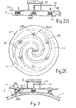
- the underside (as viewed) of the collector plate 21 is spirally grooved so as to define channels as (201) - three are shown, and shaded to make them stand out - , bounded by low walls, along which air, and emanated hydrogen, can be drawn in from the peripheral areas to the centre point, and then, through an opening (202) connected to the pipe 13, and thence out of the collector plate 21 and on to the detector 15.
- FIG 3 shows the collector device of the invention being used - as it is in Figure 1 - on a pipeline pipe (11: shown here in part only).
- the clamping magnets see Figure 4
- the collector plate 21 to flex into contact with the pipe 11, the rod and spring combination 28/25 allowing the magnets, in their holders 27, to move up and down and from side to side, so as the better to conform.
- FIG. 4 A slightly different version of the collector device of the invention is shown in Figure 4.
- This version has a different sort of carrying handle (423), and there can clearly be seen the magnet (401) recessed within the bottom holder 27, the rod 28 in its hole in the backplate 22, the spring 25 "wound” around the threaded top and bottom holders 26,27, and the string tie 200 between those two holders.
Landscapes
- Chemical & Material Sciences (AREA)
- Life Sciences & Earth Sciences (AREA)
- Health & Medical Sciences (AREA)
- Engineering & Computer Science (AREA)
- Pathology (AREA)
- Immunology (AREA)
- Physics & Mathematics (AREA)
- Analytical Chemistry (AREA)
- Biochemistry (AREA)
- General Health & Medical Sciences (AREA)
- General Physics & Mathematics (AREA)
- Food Science & Technology (AREA)
- Medicinal Chemistry (AREA)
- Molecular Biology (AREA)
- Biomedical Technology (AREA)
- Combustion & Propulsion (AREA)
- Sampling And Sample Adjustment (AREA)
- Investigating Or Analyzing Non-Biological Materials By The Use Of Chemical Means (AREA)
- Investigating And Analyzing Materials By Characteristic Methods (AREA)
Abstract
Description
- Figure 1
- shows a general view of the testing (for emanating hydrogen) of a surface in accordance with the invention;
- Figures 2A-C
- show views - perspective from above, side elevation, and top plan (in see-through) - of a collector device of the invention;
- Figure 3
- shows in side elevation the device of Figure 2B in use on a pipeline pipe; and
- Figure 4
- shows, in side elevation (like Figure 2B), part of a different embodiment of a device of the invention.
Claims (11)
- For use as the collector (21) of a hydrogen collection and detection system (12-16), a flexible plate (21) on the receptor face of which are constructed guide channels (201) along which in use hydrogen emanating from the surface (11) underlying the plate can be drawn and sent to the associated detector system (15).
- A collector plate as claimed in Claim 1, which is comprised entirely of untempered sheet stainless steel into which are formed collecting grooves (210) constituting the guide channels, and wherein the guide channel structure geometry forms a single spiral terminating at the centre (202) of the plate.
- A collector plate as claimed in either of the preceding Claims, which plate (21) is supported on a backing plate (22), the supports (225-28) being such as to permit the required flexing of the collector plate (21) to occur when the combination is pushed into operative contact with a curved test surface (11), wherein the backing plate (22) is a relatively rigid member to which the collector plate (21) is attached by flexible/bendable/pivotable/floating mounting means (25-28) disposed around the peripheries of both plates, and wherein each mounting means is a combination of a support rod (28) loosely mounted in an oversize bush (26) in the backing plate (22), the rod (28) carrying at its free end one end of a spring (25) to the other end of which the collector plate (21) is mounted.
- A collector plate as claimed in any of the preceding Claims, wherein, to hold in use the collector plate (21) against the test surface (11), the plate (21) has associated clamping means (27,401), the clamping means is a plurality of magnets (401) on the back surface of the plate (21) and spaced around the peripheral area thereof, and each magnet (401) is mounted on the backing plate (22) by magnet mounting means (25-27) that affords it limited vertical and rocking movement.
- A collector plate as claimed in Claim 4, wherein each mounting means for the collector plate on the backing plate is a combination of a support rod (28) loosely mounted in the backing plate (22) and carrying at its free end a spring (25) on which the collector plate (21) is mounted, and the spring (25) bears the magnet (401) at its free end, and wherein each magnet (401) is itself individually mounted in a holder (27) such that its active end is recessed, and can never actually come into contact with the collector plate back.
- A collector plate as claimed in either of Claims 4 and 5, wherein there are at least six magnets (401), arranged in a ring about the periphery of the collector plate (21), equidistant from each other.
- A collector plate as claimed in any of Claims 4 to 6, wherein the magnets (401) are disc shaped, and are positioned with both their axis of cylindrical symmetry and North-South poles directed normal to the plate surface, and with the North-South poles of all the magnets parallel.
- A collector plate as claimed in any of the preceding Claims, which plate (21) is provided with a skirt at or just beyond its perimeter.
- A collector plate as claimed in any of the preceding Claims, which collector plate (21) has input means for receiving a carrier gas and output means (13) for delivering, in use, the resultant mixture of carrier gas and emanated hydrogen, and which is operatively connectable to a hydrogen detector (15) for reception of the mixture of carrier gas and emanated hydrogen collected thereby and for the detection and measurement thereof.
- A hydrogen detection system comprising:a collector plate (21) as defined in Claim 9; anda hydrogen detector (15) connected to the collector plate output means (13), to receive the mixture of carrier gas and emanated hydrogen therefrom.
- A method of detecting hydrogen emanating from a surface (11), in which there is operatively applied to the surface (11) a detection system (12-16) as claimed in Claim 10, and the system is used to detect and measure the emanated hydrogen.
Applications Claiming Priority (2)
| Application Number | Priority Date | Filing Date | Title |
|---|---|---|---|
| GB0000016 | 2000-01-05 | ||
| GB0000016A GB2358060B (en) | 2000-01-05 | 2000-01-05 | Hydrogen collection and detection |
Publications (3)
| Publication Number | Publication Date |
|---|---|
| EP1114992A2 true EP1114992A2 (en) | 2001-07-11 |
| EP1114992A3 EP1114992A3 (en) | 2002-09-04 |
| EP1114992B1 EP1114992B1 (en) | 2005-05-25 |
Family
ID=9883112
Family Applications (1)
| Application Number | Title | Priority Date | Filing Date |
|---|---|---|---|
| EP00311501A Expired - Lifetime EP1114992B1 (en) | 2000-01-05 | 2000-12-20 | Device and method for hydrogen collection and detection |
Country Status (6)
| Country | Link |
|---|---|
| US (1) | US6637253B2 (en) |
| EP (1) | EP1114992B1 (en) |
| AT (1) | ATE296441T1 (en) |
| DE (1) | DE60020329T2 (en) |
| ES (1) | ES2240020T3 (en) |
| GB (1) | GB2358060B (en) |
Cited By (5)
| Publication number | Priority date | Publication date | Assignee | Title |
|---|---|---|---|---|
| KR101000940B1 (en) | 2008-09-19 | 2010-12-13 | 한국전자통신연구원 | Gas treatment device and method |
| ITPI20120109A1 (en) * | 2012-10-25 | 2014-04-26 | Letomec S R L | DEVICE AND METHOD FOR HYDROGEN PERMEATION MEASUREMENTS |
| WO2017017621A1 (en) * | 2015-07-30 | 2017-02-02 | Ion Science Limited | Hydrogen flux sensor assembly |
| US10809147B2 (en) | 2015-04-07 | 2020-10-20 | University Of New Brunswick | System and method for monitoring hydrogen flux |
| CN116465759A (en) * | 2023-04-18 | 2023-07-21 | 重庆大学 | An improved type III delamination test device and method for composite material laminates |
Families Citing this family (12)
| Publication number | Priority date | Publication date | Assignee | Title |
|---|---|---|---|---|
| US8062990B2 (en) * | 1998-05-01 | 2011-11-22 | Basf Corporation | Metal catalyst carriers and catalyst members made therefrom |
| WO2001036941A1 (en) * | 1999-11-18 | 2001-05-25 | Advanced Technology Materials, Inc. | Optical hydrogen detector |
| US7228724B2 (en) * | 2002-10-17 | 2007-06-12 | Advanced Technology Materials, Inc. | Apparatus and process for sensing target gas species in semiconductor processing systems |
| US20040163445A1 (en) * | 2002-10-17 | 2004-08-26 | Dimeo Frank | Apparatus and process for sensing fluoro species in semiconductor processing systems |
| US7080545B2 (en) * | 2002-10-17 | 2006-07-25 | Advanced Technology Materials, Inc. | Apparatus and process for sensing fluoro species in semiconductor processing systems |
| US7296458B2 (en) * | 2002-10-17 | 2007-11-20 | Advanced Technology Materials, Inc | Nickel-coated free-standing silicon carbide structure for sensing fluoro or halogen species in semiconductor processing systems, and processes of making and using same |
| US20060211253A1 (en) * | 2005-03-16 | 2006-09-21 | Ing-Shin Chen | Method and apparatus for monitoring plasma conditions in an etching plasma processing facility |
| US20080233010A1 (en) * | 2007-03-19 | 2008-09-25 | Hydrogen Discoveries, Inc. | Testing Hydrogen Flux Through Solid and Liquid Barrier Materials |
| FR2959014B1 (en) * | 2010-04-19 | 2013-01-04 | Total Raffinage Marketing | TRACKING THE CORROSION SPEED OF A METALLIC CONDUIT CONDUCTED BY A CORROSIVE FLUID |
| US10732163B2 (en) | 2017-04-28 | 2020-08-04 | Saudi Arabian Oil Company | Apparatus and method for the non-destructive measurement of hydrogen diffusivity |
| US10436741B2 (en) | 2017-04-28 | 2019-10-08 | Saudi Arabian Oil Company | Apparatus and method for the non-destructive measurement of hydrogen diffusivity |
| RU2670191C1 (en) * | 2017-05-15 | 2018-10-18 | Общество с ограниченной ответственностью "ТЕХНОЛОГИИ МОНИТОРИНГА СООРУЖЕНИЙ" | Magnetic mounting |
Family Cites Families (24)
| Publication number | Priority date | Publication date | Assignee | Title |
|---|---|---|---|---|
| US1467911A (en) * | 1920-03-31 | 1923-09-11 | Arendt Morton | Hydrogen detector |
| US2400940A (en) * | 1943-03-22 | 1946-05-28 | Mccollum Thelma | Gas detection apparatus |
| US2660053A (en) * | 1950-02-02 | 1953-11-24 | Smith Corp A O | Flexible seam testing device |
| US2751281A (en) * | 1953-02-19 | 1956-06-19 | Baker & Co Inc | Apparatus for the continuous analysis of contaminants in gases |
| US2921210A (en) * | 1957-09-30 | 1960-01-12 | Pure Oil Co | Hydrogen diffusion detection apparatus |
| NL241857A (en) * | 1958-08-20 | |||
| US3242717A (en) * | 1963-03-26 | 1966-03-29 | Bendix Corp | Hydrogen sensor |
| US3969077A (en) * | 1971-12-16 | 1976-07-13 | Varian Associates | Alkali metal leak detection method and apparatus |
| US3927555A (en) * | 1973-10-15 | 1975-12-23 | Gen Electric | Hydrogen detector system |
| US4181005A (en) * | 1976-12-06 | 1980-01-01 | Doryokuro Kakunenryo Kaihatsu Jigyodan | Hydrogen detector |
| NL7806340A (en) * | 1978-06-12 | 1979-12-14 | Hoogstraat Med Tech | METHOD AND DEVICE FOR DETERMINING A HYDROGEN CONTENT IN A GAS. |
| WO1987001205A1 (en) * | 1985-08-24 | 1987-02-26 | Analytical Security Systems Limited | Method and apparatus for detecting dangerous substances |
| JPS6466537A (en) * | 1987-09-08 | 1989-03-13 | Nippon Steel Corp | Method and apparatus for analyzing hydrogen in gas |
| JPH0623750B2 (en) * | 1988-11-19 | 1994-03-30 | 新日本製鐵株式会社 | Method and device for on-line analysis of hydrogen in molten steel |
| JP2790702B2 (en) * | 1990-03-19 | 1998-08-27 | 新日本製鐵株式会社 | Metal bolt for measuring permeated hydrogen |
| CA2035105C (en) * | 1991-01-28 | 1993-04-27 | H. Bruce Freeman | Hydrogen monitoring apparatus |
| EP0544417A1 (en) * | 1991-11-26 | 1993-06-02 | Applied Materials, Inc. | Method of detecting surface volatile materials and a detector therefore |
| JP3269234B2 (en) | 1993-12-28 | 2002-03-25 | 株式会社日立製作所 | Delivery route assembly device for paper sheets |
| DE4432218A1 (en) * | 1994-09-10 | 1996-03-14 | Draegerwerk Ag | Detection device with a gas detection element |
| US5517026A (en) * | 1995-01-20 | 1996-05-14 | The United States Of America As Represented By The Secretary Of The Army | On-the-move surface sampling head for a mass spectrometer |
| GB9608041D0 (en) * | 1996-04-18 | 1996-06-19 | Ion Science Ltd | A device for hydrogen collection |
| US6216526B1 (en) * | 1998-12-16 | 2001-04-17 | Midwest Instrument Co., Inc. | Gas sampler for molten metal and method |
| US6265222B1 (en) * | 1999-01-15 | 2001-07-24 | Dimeo, Jr. Frank | Micro-machined thin film hydrogen gas sensor, and method of making and using the same |
| US6277329B1 (en) * | 1999-03-22 | 2001-08-21 | Camp Dresser & Mckee Inc. | Dissolved hydrogen analyzer |
-
2000
- 2000-01-05 GB GB0000016A patent/GB2358060B/en not_active Expired - Fee Related
- 2000-12-20 AT AT00311501T patent/ATE296441T1/en not_active IP Right Cessation
- 2000-12-20 DE DE60020329T patent/DE60020329T2/en not_active Expired - Lifetime
- 2000-12-20 ES ES00311501T patent/ES2240020T3/en not_active Expired - Lifetime
- 2000-12-20 EP EP00311501A patent/EP1114992B1/en not_active Expired - Lifetime
-
2001
- 2001-01-03 US US09/753,527 patent/US6637253B2/en not_active Expired - Lifetime
Cited By (8)
| Publication number | Priority date | Publication date | Assignee | Title |
|---|---|---|---|---|
| KR101000940B1 (en) | 2008-09-19 | 2010-12-13 | 한국전자통신연구원 | Gas treatment device and method |
| ITPI20120109A1 (en) * | 2012-10-25 | 2014-04-26 | Letomec S R L | DEVICE AND METHOD FOR HYDROGEN PERMEATION MEASUREMENTS |
| WO2014064658A1 (en) | 2012-10-25 | 2014-05-01 | Letomec S.R.L. | A device and a method for permeation hydrogen measurements |
| US9857349B2 (en) | 2012-10-25 | 2018-01-02 | Letomec S.R.L. | Device and a method for permeation hydrogen measurements |
| RU2646801C2 (en) * | 2012-10-25 | 2018-03-07 | Летомек С.Р.Л. | Device and method for measuring hydrogen penetration |
| US10809147B2 (en) | 2015-04-07 | 2020-10-20 | University Of New Brunswick | System and method for monitoring hydrogen flux |
| WO2017017621A1 (en) * | 2015-07-30 | 2017-02-02 | Ion Science Limited | Hydrogen flux sensor assembly |
| CN116465759A (en) * | 2023-04-18 | 2023-07-21 | 重庆大学 | An improved type III delamination test device and method for composite material laminates |
Also Published As
| Publication number | Publication date |
|---|---|
| ES2240020T3 (en) | 2005-10-16 |
| DE60020329D1 (en) | 2005-06-30 |
| GB2358060B (en) | 2003-09-24 |
| US20010006008A1 (en) | 2001-07-05 |
| GB2358060A (en) | 2001-07-11 |
| DE60020329T2 (en) | 2006-05-04 |
| EP1114992A3 (en) | 2002-09-04 |
| ATE296441T1 (en) | 2005-06-15 |
| EP1114992B1 (en) | 2005-05-25 |
| US6637253B2 (en) | 2003-10-28 |
| GB0000016D0 (en) | 2000-02-23 |
Similar Documents
| Publication | Publication Date | Title |
|---|---|---|
| EP1114992B1 (en) | Device and method for hydrogen collection and detection | |
| Mason et al. | Investigation of porewater sampling methods for mercury and methylmercury | |
| RU2012110175A (en) | RIGIDITY TESTING BASED ON ACOUSTIC EMISSION FOR PDC. PCBN OR OTHER INSERTS FROM SOLID OR SUPER-SOLID MATERIAL | |
| WO2003060479A3 (en) | Sample testing device | |
| US10989610B2 (en) | Adjustable spring loaded adapter for temperature sensor | |
| JP5496703B2 (en) | Piping support device | |
| CN203534902U (en) | Flexible clamping device for concrete tensile test | |
| CN118243889B (en) | Sampling device for water quality detection | |
| MY141852A (en) | Method and apparatus for the detection of methyl isothiocyanate in air samples | |
| WO2001042764A3 (en) | Method and apparatus for measuring accumulated and instant rate of material loss or material gain | |
| US10209233B2 (en) | Hydrogen flux sensor assembly | |
| CN203758959U (en) | Inner surface flaw detecting device of ground high pressure manifold | |
| AU6598901A (en) | Method and device for measuring a component in a liquid sample | |
| CN204882415U (en) | Path pipeline fixing device | |
| RU2005126405A (en) | FASTENING SYSTEM FOR MEASURING INSTRUMENT | |
| GB2312279A (en) | Hydrogen detecting system | |
| CN211347684U (en) | Clamp for testing hardness of large-diameter pipe fitting | |
| CN212843334U (en) | A device for detecting the inner diameter of a pipe of key automobile parts | |
| KR200488207Y1 (en) | A pilot apparatus for assessment equipment of buried pipelines | |
| CN208443762U (en) | A kind of imaging board fixer | |
| JP2012068033A (en) | Jig for collecting grid and method for collecting grid using the jig | |
| NO313022B1 (en) | Method and apparatus for measuring corrosion or erosion in pipes | |
| CN222212109U (en) | Pressure vessel leakage detection device | |
| CN214702118U (en) | Underwater ice layer thickness sensor and clamp thereof | |
| CN218768355U (en) | Built-in gas alarm detector |
Legal Events
| Date | Code | Title | Description |
|---|---|---|---|
| PUAI | Public reference made under article 153(3) epc to a published international application that has entered the european phase |
Free format text: ORIGINAL CODE: 0009012 |
|
| AK | Designated contracting states |
Kind code of ref document: A2 Designated state(s): AT BE CH CY DE DK ES FI FR GB GR IE IT LI LU MC NL PT SE TR |
|
| AX | Request for extension of the european patent |
Free format text: AL;LT;LV;MK;RO;SI |
|
| PUAL | Search report despatched |
Free format text: ORIGINAL CODE: 0009013 |
|
| AK | Designated contracting states |
Kind code of ref document: A3 Designated state(s): AT BE CH CY DE DK ES FI FR GB GR IE IT LI LU MC NL PT SE TR |
|
| AX | Request for extension of the european patent |
Free format text: AL;LT;LV;MK;RO;SI |
|
| RIC1 | Information provided on ipc code assigned before grant |
Free format text: 7G 01N 1/24 A, 7G 01N 33/20 B, 7G 01N 33/00 B |
|
| 17P | Request for examination filed |
Effective date: 20030107 |
|
| AKX | Designation fees paid |
Designated state(s): AT BE CH CY DE DK ES FI FR GB GR IE IT LI LU MC NL PT SE TR |
|
| 17Q | First examination report despatched |
Effective date: 20030915 |
|
| GRAP | Despatch of communication of intention to grant a patent |
Free format text: ORIGINAL CODE: EPIDOSNIGR1 |
|
| GRAS | Grant fee paid |
Free format text: ORIGINAL CODE: EPIDOSNIGR3 |
|
| GRAA | (expected) grant |
Free format text: ORIGINAL CODE: 0009210 |
|
| AK | Designated contracting states |
Kind code of ref document: B1 Designated state(s): AT BE CH CY DE DK ES FI FR GB GR IE IT LI LU MC NL PT SE TR |
|
| PG25 | Lapsed in a contracting state [announced via postgrant information from national office to epo] |
Ref country code: FI Free format text: LAPSE BECAUSE OF FAILURE TO SUBMIT A TRANSLATION OF THE DESCRIPTION OR TO PAY THE FEE WITHIN THE PRESCRIBED TIME-LIMIT Effective date: 20050525 Ref country code: IT Free format text: LAPSE BECAUSE OF FAILURE TO SUBMIT A TRANSLATION OF THE DESCRIPTION OR TO PAY THE FEE WITHIN THE PRE;WARNING: LAPSES OF ITALIAN PATENTS WITH EFFECTIVE DATE BEFORE 2007 MAY HAVE OCCURRED AT ANY TIME BEFORE 2007. THE CORRECT EFFECTIVE DATE MAY BE DIFFERENT FROM THE ONE RECORDED.SCRIBED TIME-LIMIT Effective date: 20050525 Ref country code: AT Free format text: LAPSE BECAUSE OF FAILURE TO SUBMIT A TRANSLATION OF THE DESCRIPTION OR TO PAY THE FEE WITHIN THE PRESCRIBED TIME-LIMIT Effective date: 20050525 Ref country code: CH Free format text: LAPSE BECAUSE OF FAILURE TO SUBMIT A TRANSLATION OF THE DESCRIPTION OR TO PAY THE FEE WITHIN THE PRESCRIBED TIME-LIMIT Effective date: 20050525 Ref country code: TR Free format text: LAPSE BECAUSE OF FAILURE TO SUBMIT A TRANSLATION OF THE DESCRIPTION OR TO PAY THE FEE WITHIN THE PRESCRIBED TIME-LIMIT Effective date: 20050525 Ref country code: LI Free format text: LAPSE BECAUSE OF FAILURE TO SUBMIT A TRANSLATION OF THE DESCRIPTION OR TO PAY THE FEE WITHIN THE PRESCRIBED TIME-LIMIT Effective date: 20050525 |
|
| REG | Reference to a national code |
Ref country code: GB Ref legal event code: FG4D |
|
| REG | Reference to a national code |
Ref country code: CH Ref legal event code: EP |
|
| REG | Reference to a national code |
Ref country code: IE Ref legal event code: FG4D |
|
| REF | Corresponds to: |
Ref document number: 60020329 Country of ref document: DE Date of ref document: 20050630 Kind code of ref document: P |
|
| PG25 | Lapsed in a contracting state [announced via postgrant information from national office to epo] |
Ref country code: GR Free format text: LAPSE BECAUSE OF FAILURE TO SUBMIT A TRANSLATION OF THE DESCRIPTION OR TO PAY THE FEE WITHIN THE PRESCRIBED TIME-LIMIT Effective date: 20050825 Ref country code: DK Free format text: LAPSE BECAUSE OF FAILURE TO SUBMIT A TRANSLATION OF THE DESCRIPTION OR TO PAY THE FEE WITHIN THE PRESCRIBED TIME-LIMIT Effective date: 20050825 |
|
| REG | Reference to a national code |
Ref country code: SE Ref legal event code: TRGR |
|
| REG | Reference to a national code |
Ref country code: ES Ref legal event code: FG2A Ref document number: 2240020 Country of ref document: ES Kind code of ref document: T3 |
|
| PG25 | Lapsed in a contracting state [announced via postgrant information from national office to epo] |
Ref country code: PT Free format text: LAPSE BECAUSE OF FAILURE TO SUBMIT A TRANSLATION OF THE DESCRIPTION OR TO PAY THE FEE WITHIN THE PRESCRIBED TIME-LIMIT Effective date: 20051027 |
|
| REG | Reference to a national code |
Ref country code: CH Ref legal event code: PL |
|
| PG25 | Lapsed in a contracting state [announced via postgrant information from national office to epo] |
Ref country code: CY Free format text: LAPSE BECAUSE OF FAILURE TO SUBMIT A TRANSLATION OF THE DESCRIPTION OR TO PAY THE FEE WITHIN THE PRESCRIBED TIME-LIMIT Effective date: 20051220 |
|
| PG25 | Lapsed in a contracting state [announced via postgrant information from national office to epo] |
Ref country code: LU Free format text: LAPSE BECAUSE OF NON-PAYMENT OF DUE FEES Effective date: 20051231 Ref country code: MC Free format text: LAPSE BECAUSE OF NON-PAYMENT OF DUE FEES Effective date: 20051231 |
|
| PLBE | No opposition filed within time limit |
Free format text: ORIGINAL CODE: 0009261 |
|
| STAA | Information on the status of an ep patent application or granted ep patent |
Free format text: STATUS: NO OPPOSITION FILED WITHIN TIME LIMIT |
|
| ET | Fr: translation filed | ||
| 26N | No opposition filed |
Effective date: 20060228 |
|
| REG | Reference to a national code |
Ref country code: FR Ref legal event code: PLFP Year of fee payment: 16 |
|
| REG | Reference to a national code |
Ref country code: FR Ref legal event code: PLFP Year of fee payment: 17 |
|
| REG | Reference to a national code |
Ref country code: FR Ref legal event code: PLFP Year of fee payment: 18 |
|
| PGFP | Annual fee paid to national office [announced via postgrant information from national office to epo] |
Ref country code: SE Payment date: 20181228 Year of fee payment: 19 Ref country code: IE Payment date: 20181228 Year of fee payment: 19 |
|
| PGFP | Annual fee paid to national office [announced via postgrant information from national office to epo] |
Ref country code: FR Payment date: 20181231 Year of fee payment: 19 |
|
| PGFP | Annual fee paid to national office [announced via postgrant information from national office to epo] |
Ref country code: DE Payment date: 20181228 Year of fee payment: 19 Ref country code: ES Payment date: 20190122 Year of fee payment: 19 Ref country code: NL Payment date: 20181228 Year of fee payment: 19 |
|
| PGFP | Annual fee paid to national office [announced via postgrant information from national office to epo] |
Ref country code: BE Payment date: 20181228 Year of fee payment: 19 |
|
| REG | Reference to a national code |
Ref country code: DE Ref legal event code: R119 Ref document number: 60020329 Country of ref document: DE |
|
| REG | Reference to a national code |
Ref country code: SE Ref legal event code: EUG |
|
| REG | Reference to a national code |
Ref country code: NL Ref legal event code: MM Effective date: 20200101 |
|
| REG | Reference to a national code |
Ref country code: BE Ref legal event code: MM Effective date: 20191231 |
|
| PG25 | Lapsed in a contracting state [announced via postgrant information from national office to epo] |
Ref country code: NL Free format text: LAPSE BECAUSE OF NON-PAYMENT OF DUE FEES Effective date: 20200101 |
|
| PG25 | Lapsed in a contracting state [announced via postgrant information from national office to epo] |
Ref country code: DE Free format text: LAPSE BECAUSE OF NON-PAYMENT OF DUE FEES Effective date: 20200701 Ref country code: IE Free format text: LAPSE BECAUSE OF NON-PAYMENT OF DUE FEES Effective date: 20191220 Ref country code: FR Free format text: LAPSE BECAUSE OF NON-PAYMENT OF DUE FEES Effective date: 20191231 Ref country code: SE Free format text: LAPSE BECAUSE OF NON-PAYMENT OF DUE FEES Effective date: 20191221 |
|
| PG25 | Lapsed in a contracting state [announced via postgrant information from national office to epo] |
Ref country code: BE Free format text: LAPSE BECAUSE OF NON-PAYMENT OF DUE FEES Effective date: 20191231 |
|
| REG | Reference to a national code |
Ref country code: ES Ref legal event code: FD2A Effective date: 20210525 |
|
| PG25 | Lapsed in a contracting state [announced via postgrant information from national office to epo] |
Ref country code: ES Free format text: LAPSE BECAUSE OF NON-PAYMENT OF DUE FEES Effective date: 20191221 |