EP1114927A2 - Estimation method - Google Patents
Estimation method Download PDFInfo
- Publication number
- EP1114927A2 EP1114927A2 EP00311450A EP00311450A EP1114927A2 EP 1114927 A2 EP1114927 A2 EP 1114927A2 EP 00311450 A EP00311450 A EP 00311450A EP 00311450 A EP00311450 A EP 00311450A EP 1114927 A2 EP1114927 A2 EP 1114927A2
- Authority
- EP
- European Patent Office
- Prior art keywords
- brake booster
- pressure
- manifold
- booster pressure
- engine
- Prior art date
- Legal status (The legal status is an assumption and is not a legal conclusion. Google has not performed a legal analysis and makes no representation as to the accuracy of the status listed.)
- Granted
Links
Images






Classifications
-
- F—MECHANICAL ENGINEERING; LIGHTING; HEATING; WEAPONS; BLASTING
- F02—COMBUSTION ENGINES; HOT-GAS OR COMBUSTION-PRODUCT ENGINE PLANTS
- F02D—CONTROLLING COMBUSTION ENGINES
- F02D41/00—Electrical control of supply of combustible mixture or its constituents
- F02D41/22—Safety or indicating devices for abnormal conditions
- F02D41/222—Safety or indicating devices for abnormal conditions relating to the failure of sensors or parameter detection devices
-
- B—PERFORMING OPERATIONS; TRANSPORTING
- B60—VEHICLES IN GENERAL
- B60T—VEHICLE BRAKE CONTROL SYSTEMS OR PARTS THEREOF; BRAKE CONTROL SYSTEMS OR PARTS THEREOF, IN GENERAL; ARRANGEMENT OF BRAKING ELEMENTS ON VEHICLES IN GENERAL; PORTABLE DEVICES FOR PREVENTING UNWANTED MOVEMENT OF VEHICLES; VEHICLE MODIFICATIONS TO FACILITATE COOLING OF BRAKES
- B60T17/00—Component parts, details, or accessories of power brake systems not covered by groups B60T8/00, B60T13/00 or B60T15/00, or presenting other characteristic features
- B60T17/02—Arrangements of pumps or compressors, or control devices therefor
-
- F—MECHANICAL ENGINEERING; LIGHTING; HEATING; WEAPONS; BLASTING
- F02—COMBUSTION ENGINES; HOT-GAS OR COMBUSTION-PRODUCT ENGINE PLANTS
- F02D—CONTROLLING COMBUSTION ENGINES
- F02D2200/00—Input parameters for engine control
- F02D2200/02—Input parameters for engine control the parameters being related to the engine
- F02D2200/04—Engine intake system parameters
- F02D2200/0406—Intake manifold pressure
- F02D2200/0408—Estimation of intake manifold pressure
-
- Y—GENERAL TAGGING OF NEW TECHNOLOGICAL DEVELOPMENTS; GENERAL TAGGING OF CROSS-SECTIONAL TECHNOLOGIES SPANNING OVER SEVERAL SECTIONS OF THE IPC; TECHNICAL SUBJECTS COVERED BY FORMER USPC CROSS-REFERENCE ART COLLECTIONS [XRACs] AND DIGESTS
- Y02—TECHNOLOGIES OR APPLICATIONS FOR MITIGATION OR ADAPTATION AGAINST CLIMATE CHANGE
- Y02T—CLIMATE CHANGE MITIGATION TECHNOLOGIES RELATED TO TRANSPORTATION
- Y02T10/00—Road transport of goods or passengers
- Y02T10/10—Internal combustion engine [ICE] based vehicles
- Y02T10/40—Engine management systems
Definitions
- the invention relates to internal combustion engines having vacuum assisted brake systems.
- manifold pressure is a common internal combustion engine parameter used in various engine control systems. To reduce system cost, it is known to estimate manifold pressure from engine mass air flow and engine speed along with known engine relationships. It is also common to improve accuracy of this estimated manifold pressure with manifold temperature and exhaust gas recirculation amounts.
- mass air flow from manifold pressure.
- measured manifold pressure, and also manifold temperature are used with various predetermined engine maps and engine speed to estimate engine mass air flow.
- This estimated engine mass air flow can then be used to determine fuel injection amounts and various other parameters. It is further known to improve accuracy of engine mass air flow by including exhaust gas recirculation amounts.
- the inventors have recognized a disadvantage with the above approaches.
- such estimation methods can have errors due to engine variation, engine aging, and various other effects. These potential errors can degrade engine performance, fuel economy, and emissions. For example, engine characteristics relating manifold pressure and mass air flow may change from one engine to another. Similarly, engine aging affects may change heat transfer characteristics, thereby causing errors to arise.
- An object of the present invention is to improve estimates of operating parameters.
- a method for determining an operating parameter of a vehicle system having an internal combustion engine, the engine having a manifold, the manifold coupled through a check valve to a brake booster comprises measuring a brake booster pressure; and calculating an estimate of the operating parameter based on said brake booster pressure.
- the present invention recognizes the relationships between brake booster pressure and other operating parameters and then uses them to improve estimation and engine control.
- An advantage of the above aspect of the present invention is that more accurate engine control from improved estimates of operating parameters is possible.
- Another advantage of the above aspect of the present is that the engine control systems can account for effects from engine variation and engine aging.
- an engine control method for a vehicle system having an internal combustion engine the engine having a manifold, the manifold coupled through a check valve to a brake booster, the method comprising: measuring a brake booster pressure; determining an operating parameter of the vehicle system based on said brake booster pressure; and modifying a control signal based on said operating parameter.
- an article of manufacture comprising a computer storage medium having a computer program encoded therein for determining an operating parameter of an internal combustion engine, the engine having a manifold, the manifold coupled through a check valve to a brake booster, said computer storage medium comprising: code for measuring a brake booster pressure; and code for calculating an estimate of the engine operating parameter based on said brake booster pressure and a predetermined value representing pressure drop across the check valve.
- An advantage of the above aspect of the present invention is that more accurate engine control from improved estimates of operating parameters is possible.
- Another advantage of the above aspect of the present is that the engine control systems can account for effects from engine variation and engine ageing.
- Direct injection spark ignited internal combustion engine 10 comprising a plurality of combustion chambers, is controlled by electronic engine controller 12.
- Combustion chamber 30 of engine 10 is shown in Figure 1 including combustion chamber walls 32 with piston 36 positioned therein and connected to crankshaft 40.
- piston 30 includes a recess or bowl (not shown) to help in forming stratified charges of air and fuel.
- Combustion chamber 30 is shown communicating with intake manifold 44 and exhaust manifold 48 via respective intake valves 52a and 52b (not shown), and exhaust valves 54a and 54b (not shown).
- Fuel injector 66 is shown directly coupled to combustion chamber 30 for delivering liquid fuel directly therein in proportion to pulse width of signal fpw received from controller 12 via conventional electronic driver 68.
- -Fuel is delivered to fuel injector 66 by a conventional high pressure fuel system (not shown) including a fuel tank, fuel pumps, and a fuel rail.
- Intake manifold 44 is shown communicating with throttle body 58 via throttle plate 62.
- throttle plate 62 is coupled to electric motor 94 so that the position of throttle plate 62 is controlled by controller 12 via electric motor 94.
- This configuration is commonly referred to as electronic throttle control (ETC) which is also utilised during idle speed control.
- ETC electronic throttle control
- a bypass air passageway is arranged in parallel with throttle plate 62 to control inducted airflow during idle speed control via a throttle control valve positioned within the air passageway.
- Exhaust gas oxygen sensor 76 is shown coupled to exhaust manifold 48 upstream of catalytic converter 70.
- sensor 76 provides signal UEGO to controller 12 which converts signal UEGO into a relative air/fuel ratio ⁇ .
- Signal UEGO is used to advantage during feedback air/fuel control in a conventional manner to maintain average air/fuel at a desired air/fuel ratio.
- Conventional distributorless ignition system 88 provides ignition spark to combustion chamber 30 via spark plug 92 in response to spark advance signal SA from controller 12.
- Controller 12 causes combustion chamber 30 to operate in either a homogeneous air/fuel mode or a stratified air/fuel mode by controlling injection timing.
- controller 12 activates fuel injector 66 during the engine compression stroke so that fuel is sprayed directly into the bowl of piston 36. Stratified air/fuel layers are thereby formed. The strata closest to the spark plug contains a stoichiometric mixture or a mixture slightly rich of stoichiometry, and subsequent strata contain progressively leaner mixtures.
- controller 12 activates fuel injector 66 during the intake stroke so that a substantially homogeneous air/fuel mixture is formed when ignition power is supplied to spark plug 92 by ignition system 88.
- Controller 12 controls the amount of fuel delivered by fuel injector 66 so that the homogeneous air/fuel mixture in chamber 30 can be selected to be at stoichiometry, a value rich of stoichiometry, or a value lean of stoichiometry.
- the stratified air/fuel mixture will always be at a value lean of stoichiometry, the exact air/fuel being a function of the amount of fuel delivered to combustion chamber 30.
- An additional split mode of operation wherein additional fuel is injected during the exhaust stroke while operating in the stratified mode is available.
- An additional split mode of operation wherein additional fuel is injected during the intake stroke while operating in the stratified mode is also available, where a combined homogeneous and split mode is available.
- Nitrogen oxide (NOx) absorbent or trap 72 is shown positioned downstream of catalytic converter 70. NOx trap 72. absorbs NOx when engine 10 is operating lean of stoichiometry. The absorbed NOx is subsequently reacted with HC and catalysed during a NOx purge cycle when controller 12 causes engine 10 to operate in either a rich homogeneous mode or a stoichiometric homogeneous mode.
- NOx Nitrogen oxide
- Exhaust gas recirculation tube 120 is also shown coupled between intake manifold 44 and exhaust manifold 48. Exhaust gas recirculation valve 122 is place in exhaust gas recirculation tube 120 to control an amount of recycled exhaust flow. Sensor 124 indicates EGR flow ( ).
- Vacuum brake booster 130 is also shown fluidly communicating with manifold 44 via tube 132.
- Check valve 134 is placed in tube 132 to allow air to pass from vacuum brake booster 130 to manifold 44 only when manifold pressure ( ) is less than brake booster pressure ( ).
- check valve 134 allows vacuum to -be retained in Vacuum brake booster 130 even when manifold pressure ( ) is higher than brake booster pressure ( ).
- Vacuum brake booster 130 is also coupled to hydraulic brake system 136 and brake pedal 138.
- Brake pedal position is measured via sensor 140 and provides signal ( b ), which represents position of brake pedal 138. In this example, sensor 140 provides a continuous signal that allows determination of brake pedal position throughout an entire span.
- sensor 140 can also provide a switch signal that represents when brake pedal 138 has travelled past a predetermined distance.
- Sensor 142 provides an indication of brake booster pressure ( ). In this example, sensor 142 provides a continuous signal that allows determination of brake booster pressure throughout an entire span. However, sensor 142 can also provide a switch signal that represents when brake booster pressure has reached a predetermined value.
- Sensor 144 provides an indication of hydraulic brake pressure ( ). In this example, sensor 144 provides a continuous signal that allows determination of hydraulic brake pressure throughout an entire span. However, sensor 144 can also provide a switch signal that represents when hydraulic brake pressure has reached a predetermined value.
- Controller 12 is shown in Figure 1 as a conventional microcomputer including: microprocessor unit 102, input/output ports 104, an electronic storage medium for executable programs and calibration values, shown as read-only memory-chip 106 in this particular example, random access memory 108, keep alive memory 110, and a conventional data bus.
- Controller 12 is shown receiving various signals from sensors coupled to engine 10, in addition to those signals previously discussed, including: measurement of inducted mass air flow ( ) from mass air flow sensor 100 coupled to throttle body 58, engine coolant temperature (ECT) from temperature sensor 112 coupled to cooling sleeve 114, a profile ignition pickup signal (PIP) from Hall effect sensor 118 coupled to crankshaft 40, throttle position ( ) from throttle position sensor 120, and absolute Manifold Pressure Signal ( ) from sensor 122.
- Engine speed signal ( ⁇ ) is generated by controller 12 from signal PIP in a conventional manner and manifold pressure signal ( ) provides an indication of engine load. Note that the symbol ⁇ is used to specifically indicate a measured variable when necessary, while the symbol ⁇ is used to specifically indicate an estimate when necessary.
- temperature Tcat is provided by temperature sensor 124 and temperature Ttrp is provided by temperature sensor 126.
- temperature sensor 124 is provided by temperature sensor 124 and temperature Ttrp is provided by temperature sensor 126.
- these values may be estimated rather than measured.
- i is an index that occurs at execution of computation loop representing either fixed or variable sample time or engine firings and k is an index representing driving cycles.
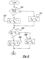
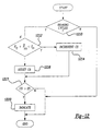
- a routine is described for estimating brake booster pressure from measured manifold pressure ( ) and a brake actuation signal.
- step 210 a determination is made as to whether a braking cycle has been completed.
- a braking cycle is determined from brake actuation signal.
- the brake actuation signal can be generated from brake pedal position ( ), or hydraulic brake pressure ( ). In other words, either of these signals can be used to determine when the brakes have been applied and released and an amount of vacuum has been consumed by vacuum brake booster 130.
- brake pedal position ( ) is a switch
- cycling of this switch can be used as an indication that a braking cycle has been detected.
- brake pedal position ( b ) is a continuous signal, when this signal goes back and forth across a certain level, this can be used to indicate that a braking cycle has been detected. Still other methods can be used for determining brake actuation, such as, for example, hydraulic brake pressure, displacement hydraulic braking actuators, or parameters of electric brake actuators.
- step 212 temporary estimated brake booster pressure ( p and t / bb ) is set equal to previously estimated brake booster pressure ( p and i -1 / bb ) and predetermined value G.
- Predetermined value G represents an amount of vacuum, or pressure, that is used by vacuum brake booster 130 when actuating the braking system.
- step 214 temporary estimated brake booster pressure ( p and t / bb ) is set equal to previously estimated brake booster pressure ( p and i -1 / bb ).
- step 216 a determination is made as to whether temporary estimated brake booster pressure ( p and t / bb ) is greater than measured manifold pressure ( ).
- current estimated brake booster pressure ( p and t / bb ) is set equal to measured manifold pressure ( ) minus predetermined value H.
- Predetermined value H represents the pressure drop across check valve 134.
- the current estimated brake booster pressure ( p and i / bb ) is set equal to temporary estimated brake booster pressure ( p and t / bb ).
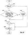
- step 310 a determination is made as to whether a braking cycle has been completed as described previously with respect to step 210.
- the routine continues to step 312 where estimated temporary brake booster pressure ( p and t / bb ) is set equal to the previously estimated brake booster pressure ( p and i -1 / bb ) and predetermined value G.
- Predetermined value G represents an amount of vacuum, or pressure, that is used by vacuum brake booster 130 when actuating the braking system.
- step 314 temporary estimated brake booster pressure ( p and t / bb ) is set equal to the previously estimated brake booster pressure ( p and i -1 / bb ).
- step 315 manifold pressure is estimated from other engine parameters using function g and parameters: , , and ⁇ . Those skilled in the art will recognise various method for estimating manifold pressure these parameters, including modifications for temperature, heat transfer, and various other corrections.
- step 316 a determination is made as to whether temporary estimated brake booster pressure ( p and t / bb ) is greater than measured manifold pressure ( ).
- current estimated brake booster pressure ( p and i / bb ) is set equal to the measured manifold pressure ( ) minus predetermined value H.
- Predetermined value H represents the pressure drop across check valve 134.
- the current estimated brake booster pressure ( p and i / bb ) is set equal to the temporary estimated brake booster pressure ( p and t / bb ).
- estimated brake booster pressure described above herein can be used for engine and vehicle control.
- estimated brake booster pressure can be used to determine a desired combustion mode.
- estimated brake booster pressure can be used to disable lean or stratified combustion when estimated brake booster pressure is greater than a predetermined pressure value.
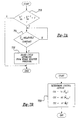
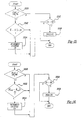
- step 410 a determination is made as to whether measured brake booster pressure ( ) is decreasing. In a preferred embodiment, this is performed by comparing successive measurements of brake booster pressure to one another. When it is determined that brake booster pressure is decreasing, the routine continues to step 412.
- step 412 manifold pressure is estimated based on measured brake booster pressure ( ) and predetermined value H. Predetermined value H represents pressure drop across check valve 134.
- step 412 a flag is set to KNOWN. Otherwise, the routine continues to step 415, where the flag is set to UNKNOWN.
- estimated manifold pressure ( p and m ) can be determined from the brake booster pressure whenever the measured brake booster pressure is decreasing.
- various different filtering techniques can be used such as high pass filtering and low pass filtering.
- limit values can be used to determine when brake booster pressure is decreasing greater than a predetermined value, and only inferring manifold pressure from brake booster pressure when it is decreasing greater than this predetermined value.
- Those skilled in the art will recognized various methods of determining whether a parameter is decreasing, or decreasing by a predetermined amount, or decreasing at a predetermined rate.
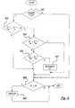
- step 510 a determination is made as to whether the flag equals KNOWN. When the answer to step 510 is NO, value L is set equal to zero in step 512. Otherwise, in step 514, value L is determined as a function of measured brake booster pressure ( ) and a previously estimated manifold pressure ( p and i -1 / m ) as well as value H.
- the current estimated manifold pressure ( p and i / m ) is based on previous estimated manifold pressure ( p and i -1 / m ) as well as measured mass airflow ( ) and engine speed ( ⁇ ) and value L.
- manifold pressure using other parameters such as mass airflow and engine speed, and then correct this estimate based on measured brake booster pressure whenever brake booster pressure is decreasing.
- An advantage of this aspect of the present invention is that it is possible to accurately estimate manifold pressure even when brake booster pressure is not decreasing.
- parameters A and B are system parameters which represent the system dynamics and input dynamics as is known to those skilled in the art.
- value L can be learned in memory as a function of engine speed and engine load.
- value L represents the error between the estimate using other variables and the estimate using the brake booster pressure.
- Value L also represents what is known to those skilled in the art as an observer structure.
- function f can be a simple gain, or the sign function, or many other functions known to those skilled in the art of estimators, observers, and modern estimation theory.
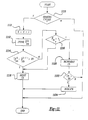
- step 610 a determination is made as to whether a flag equals KNOWN. If the answer to step 610 is YES, the routine continues to step 612, where engine mass airflow is estimated based on measured brake booster pressure ( ) and measured engine speed ( ⁇ ). In step 614, engine speed is estimated based on measured brake booster pressure ( ) and measured mass airflow ( ). In step 616, throttle position is estimated based on measured brake booster ( ) pressure and engine speed ( ⁇ ). In step 618, EGR flow is estimated based on measured brake booster pressure ( ), measured mass airflow ( ), and measured engine speed ( ⁇ ).
- measured mass airflow ( ) can also be used to improve the throttle position estimate ( ⁇ and t ).
- Figure 7A estimates brake system parameters from brake booster pressure.
- a braking cycle it is possible to determine a predicted brake pedal position profile, or a predicted hydraulic brake pressure profile. For example, when a braking cycle is estimated, it is possible to determine that the brake pedal has been depressed by a first predetermined amount and has also been released by a second predetermined amount. Similarly, it is possible to determine that the hydraulic brake pressure reached a first predetermined amount and has also been released by a second predetermined amount
- step 710 a determination is made as to whether measured brake booster pressure is increasing.
- brake booster pressure is increasing when it is greater than a previously measured brake booster pressure and a predetermined value J.
- various other methods for determining whether brake booster pressure is increasing such as, for example, high pass filtering brake booster pressure, comparing the rate of change of brake booster pressure to a limit value rate of change, and various other methods.
- a determination is made as to whether measured brake booster pressure ( ) is relatively constant indicating that the brake actuation is completed.
- the routine determines that a braking cycle has been completed in step 712. In other words, the routine determines brake system operation based on increasing brake booster pressure. Therefore, it is possible to determine whether a braking cycle should have been estimated from other braking system parameters such as, for example, brake pedal position or hydraulic brake pressure. Further it is possible to
- estimated operating parameters described above herein can be used for engine and vehicle control.
- estimated manifold pressure or mass air flow can be used to determine desired fuel injection amounts, fuel injection timings, combustion modes ignition timings, exhaust gas recirculation amounts, and other engine control parameters.
- a fuel injection amount can be adjusted based on estimated airflow or manifold pressure based on the measured brake booster pressure.
- control signals CS1, CS2, and CS3 are calculated using functions h1 , h2 , and h3 and estimated parameters, p and m , m and air , and ⁇ and t .
- Control signals CS1, CS2, and CS3 can represent: a desired fuel injection amount, a desired ignition timing amount, a desired fuel injection timing, a desired throttle position, or any other control signal known to those skilled in the art to benefit from information regarding manifold pressure, mass air flow, and/or throttle position.
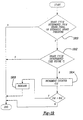
- step 810 a determination is made as to whether measured brake booster pressure is greater than the sum of measured manifold pressure and predetermined value K1.
- Value K1 represents the maximum amount of pressure drop across a properly functioning check value.
- step 814 a determination is made as to whether counter C1 is greater than limit value E1.
- step 814 an indication is created in step 814 to indicate possible degradation of sensor 142.
- step 910 a determination is made as to whether a braking cycle has been determined. Braking cycle is determined as described previously herein with reference to step 210.
- step 910 a determination is made as to whether previously measured brake booster pressure with less than previously measured manifold pressure plus predetermined value K2. In other words, a determination is made as to whether if the brakes were cycled between the current measurement and the previous measurement, it would be possible for the brake booster pressure to increase by a measurable amount knowing what the previously measured manifold pressure was.
- step 912 determines whether the current measured manifold pressure is less than the previously measured brake booster pressure. In other words, a determination is made as to whether the current measured manifold pressure has decreased below the previously measured brake booster pressure indicating that it is not possible to determine braking cycles from measured brake booster pressure. Thus, when the answer to step 914 is NO, the routine continues to step 916 to determine whether measured brake booster pressure has increased.
- step 916 conditions are such that a braking cycle should have caused brake booster pressure to increase since brake booster pressure is below manifold pressure.
- the routine continues to step 917 to increment counter C2.
- step 920 a determination is made as to whether counter C2 is greater than limit E2.
- an indication is provided in step 922.
- measured manifold pressure can be replaced in this routine by estimated manifold pressure from sensors such as, for example, engine speed and mass airflow.
- degradation in measured brake booster pressure is determined when brake booster pressure does not approach manifold pressure when measured brake booster pressure is less than measured manifold pressure.
- step 1010 a determination is made as to whether the vehicle has been driven. In other words, whether the vehicle has been started and driven over a predetermined speed or more than a predetermined distance.
- step 1012 a determination is made in step 1012 as to whether measured brake booster pressure is changing. This can be done by determining whether measured brake booster pressure changes by a predetermined amount. This predetermined amount determines that regular sensor noise and variation do not falsely indicate that measured brake booster pressure is properly changing.
- step 1012 is NO, counter C3 is incremented in step 1014.
- step 1016 a determination is made as to whether counter C3 is greater than limit value E3.
- an indication is provided in step 1018.
- counter C4 is reset to zero in step 1020.
- step 1110 a determination is made as to whether the a braking cycle has been detected as described previously herein with respect to step 210.
- step 1110 a determination is made as to whether the a braking cycle has been detected as described previously herein with respect to step 210.
- step 1114 a determination is made as to whether the absolute value of the difference between successive measurements ob measured brake booster pressure after brake cycling is greater than value E5.
- step 1116 a determination is made as to whether measured manifold pressure is greater than value T1.
- step 1116 When the answer to step 1116 is NO, the routine continues to step 1118 where counter C5 is reset. Otherwise, in step 1120, counter C5 is incremented and determined whether it is greater than limit value E6 in step 1122. When the answer to step 1122 is YES, an indication is proceeded in step 1124. In other words, if brake booster pressure is not changing even after actuation of the brakes when manifold pressure is greater than a value T1, degradation is detected.
- step 1210 a determination is made as to whether a braking cycle has been completed as described previously herein with respect to Figure 2 in step 210.
- manifold pressure can be measured from a manifold pressure sensor or estimated using parameters such as engine speed and mass airflow. Alternatively, throttle position and engine speed can be used.
- step 1212 a determination is made as to whether a brake cycling should cause brake booster pressure to approach manifold pressure.
- step 1212 When the answer to step 1212 is NO, counter C5 is reset in step 1216. Otherwise, in step 1214, counter C5 is incremented. Then, in step 1218, a determination is made as to whether counter C5 is greater than limit value E5. When the answer to step 1218 is YES, an indication is provided in step 1220.
- value K2 represents a maximum amount of pressure drop across check valve 134 or a maximum amount of measurement air in both determining manifold pressure and brake booster pressure that can be tolerated.
- step 310 a determination is made as to whether flag equals KNOWN.
- step 1310 a determination is made as to whether the absolute value of the difference between measured manifold pressure and estimated manifold pressure from either step 412 or step 516 is greater than maximum air value F1.
- step 1314 a determination is made as to whether counter C6 is greater than limit value E6.
- step 1318 an indication is provided in step 1318.
- step 1410 a determination is made as to whether a brake cycle has been estimated as described previously herein with respect to Figure 7.
- the routine continues to step 1412.
- step 1412 a determination is made as to whether brake cycle has been determined from either brake pedal actuation or hydraulic brake pressure measurement as described previously herein with respect Figure 210.
- step 1416 a determination is made as to whether counter C7 is greater than limit value E7.
- step 1418 an indication is provided in step 1418.
- step 1510 a determination is made as to whether flag equal KNOWN.
- step 1512 the absolute value of the difference between measured engine speed and estimated engine speed determined from step 614 is greater than the maximum difference value F2.
- step 1516 a determination is made as to whether counter C8 is greater than limit value E8.
- step 1518 an indication is provided in step 1518.
- step 1610 a determination is made as to whether flag equal KNOWN.
- step 1610 the routine continues to step 1612, where the absolute value of the difference between measured mass air flow and estimated mass air flow determined from step 612 is greater than the maximum difference value F3.
- step 1614 the routine continues to step 1614 and increments counter C9.
- step 1616 a determination is made as to whether counter C9 is greater than limit value E9.
- an indication is provided in step 1618.
- step 1710 a determination is made as to whether flag equal KNOWN.
- step 1710 the routine continues to step 1712, where the absolute value of the difference between measured mass air flow and estimated throttle position determined from step 616 is greater than the maximum difference value F4.
- step 1714 the routine continues to step 1714 and increments counter C10.
- step 1716 a determination is made as to whether counter C10 is greater than limit value E10.
- step 1718 an indication is provided in step 1718.
- step 1810 a determination is made as to whether flag equal KNOWN.
- flag equal KNOWN When the answer to step 1810 is YES, then, as described previously herein, it is possible to estimate exhaust gas recirculation flow from measured brake booster pressure and other operating parameters.
- the routine continues to step 1812, where the absolute value of the difference between measured exhaust gas recirculation flow and estimated exhaust gas recirculation flow determined from step 618 is greater than the maximum difference value F5.
- step 1814 increments counter C11.
- step 1816 a determination is made as to whether counter C11 is greater than limit value E11.
- step 1818 an indication is provided in step 1818.
- step 1910 a determination is made as to whether a brake cycle has been determine from the brake pedal or hydraulic brake pressure as described previously herein with respect to step 210.
- counter C12 is incremented in step 1914.
- step 1916 a determination is made as to whether counter C12 is greater than limit value E12.
- an indication is provided in step 1918.
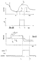
- estimated manifold pressure is shown using information from both measured airflow and engine speed, and from measured brake booster pressure. Before time t3, manifold pressure is estimated from airflow and engine speed. Then, from time t3 to t4, where the flag is set to KNOWN, both airflow and engine speed and measured brake booster pressure are used. As shown, the estimate from airflow and engine is corrected during this time to improve the accuracy of estimated manifold pressure. Then, after time t4, only airflow and engine are again used.
Landscapes
- Engineering & Computer Science (AREA)
- Mechanical Engineering (AREA)
- Chemical & Material Sciences (AREA)
- Combustion & Propulsion (AREA)
- General Engineering & Computer Science (AREA)
- Transportation (AREA)
- Valves And Accessory Devices For Braking Systems (AREA)
- Combined Controls Of Internal Combustion Engines (AREA)
- Control Of Vehicle Engines Or Engines For Specific Uses (AREA)
- Braking Systems And Boosters (AREA)
Abstract
Description


Claims (10)
- A method for determining an operating parameter of a vehicle system having an internal combustion engine (10), the engine having a manifold (44), the manifold coupled through a check valve (134) to a brake booster (130), the method comprising:measuring a brake booster pressure; andcalculating an estimate of the operating parameter based on said brake booster pressure.
- A method as claimed in Claim 1, wherein the operating parameter is a pressure in the manifold or an air mass flow.
- A method as claimed in Claim 2, wherein the operating parameter is an air mass flow entering the engine or manifold.
- A method as claimed in Claim 2, wherein the operating parameter is a throttle position of a throttle coupled to the manifold.
- A method as claimed in Claim 1, wherein said calculating further comprises calculating an estimate of the operating parameter based on said brake booster pressure when said brake booster pressure is decreasing or decreasing.
- A method as claimed in Claim 5, wherein said operating parameter is a manifold pressure, wherein said calculating further comprises calculating said manifold pressure based on said brake booster pressure when said brake booster pressure is decreasing.
- A method as claimed in Claim 6, wherein said calculating said estimate of said manifold pressure based on said brake booster pressure when said brake booster pressure is decreasing further comprises calculating said estimate of said manifold pressure based on said brake booster pressure and a predetermined value representing pressure drop across the check valve.
- A method as claimed in Claim 6, further comprising determining an estimate of a mass air flow through the engine based on said estimate of said manifold pressure.
- An engine control method for a vehicle system having an internal combustion engine, the engine having a manifold, the manifold coupled through a check valve to a brake booster, the method comprising:measuring a brake booster pressure;determining an operating parameter of the vehicle system based on said brake booster pressure; andmodifying a control signal based on said operating parameter.
- An article of manufacture comprising:
a computer storage medium having a computer program encoded therein for determining an operating parameter of an internal combustion engine, the engine having a manifold, the manifold coupled through a check valve to a brake booster, said computer storage medium comprising:code for measuring a brake booster pressure; andcode for calculating an estimate of the engine operating parameter based on said brake booster pressure and a predetermined value representing pressure drop across the check valve.
Applications Claiming Priority (2)
| Application Number | Priority Date | Filing Date | Title |
|---|---|---|---|
| US09/479,173 US6880532B1 (en) | 2000-01-07 | 2000-01-07 | Engine operation parameter estimation method |
| US479173 | 2000-01-07 |
Publications (3)
| Publication Number | Publication Date |
|---|---|
| EP1114927A2 true EP1114927A2 (en) | 2001-07-11 |
| EP1114927A3 EP1114927A3 (en) | 2002-05-08 |
| EP1114927B1 EP1114927B1 (en) | 2006-07-26 |
Family
ID=23902949
Family Applications (1)
| Application Number | Title | Priority Date | Filing Date |
|---|---|---|---|
| EP00311450A Expired - Lifetime EP1114927B1 (en) | 2000-01-07 | 2000-12-20 | Estimation method |
Country Status (3)
| Country | Link |
|---|---|
| US (3) | US6880532B1 (en) |
| EP (1) | EP1114927B1 (en) |
| DE (1) | DE60029553T2 (en) |
Families Citing this family (31)
| Publication number | Priority date | Publication date | Assignee | Title |
|---|---|---|---|---|
| US6990858B2 (en) * | 2000-01-07 | 2006-01-31 | Ford Global Technologies, Llc | System and method for detection of degradation of vacuum brake booster sensor |
| FR2829451B1 (en) * | 2001-09-11 | 2003-12-19 | Bosch Gmbh Robert | METHOD FOR CALIBRATING A PNEUMATIC SUPPORT SERVOMOTOR FOR A MOTOR VEHICLE BRAKING CIRCUIT |
| US20060247975A1 (en) * | 2003-12-30 | 2006-11-02 | Craig Shapiro | Processes and systems employing multiple sources of funds |
| DE102005009423A1 (en) * | 2005-03-02 | 2006-09-14 | Robert Bosch Gmbh | Method for detecting the Aussteuerpunkts a vacuum brake booster |
| US7467544B2 (en) * | 2005-06-13 | 2008-12-23 | Gm Global Technology Operations, Inc. | Brake booster vacuum sensor rationality check |
| CN101956621B (en) * | 2005-08-05 | 2013-12-25 | 罗伯特.博世有限公司 | Fuel injection system for internal combustion engine |
| US7458364B2 (en) | 2005-08-05 | 2008-12-02 | Scion-Sprays Limited | Internal combustion engine having a fuel injection system |
| US20070028899A1 (en) * | 2005-08-05 | 2007-02-08 | Jeffrey Allen | Fuel injection unit |
| WO2007082932A1 (en) * | 2006-01-20 | 2007-07-26 | Continental Teves Ag & Co. Ohg | Vacuum brake booster and method for the operation thereof |
| US7878053B2 (en) * | 2006-12-22 | 2011-02-01 | Gm Global Technology Operations, Inc. | Engine off brake booster leak diagnostic systems and methods |
| US8177309B2 (en) * | 2008-05-02 | 2012-05-15 | GM Global Technology Operations LLC | Braking booster system leak diagnostics |
| CA2801334C (en) | 2010-06-03 | 2020-03-10 | Polaris Industries Inc. | Electronic throttle control |
| DE102011088938A1 (en) * | 2011-01-24 | 2012-07-26 | Continental Teves Ag & Co. Ohg | Method for monitoring the signal value of a vacuum sensor |
| DE102012201436A1 (en) * | 2012-02-01 | 2013-08-01 | Robert Bosch Gmbh | A brake operation detecting apparatus and method for detecting an operation of a brake operating member of a brake system |
| US9205717B2 (en) | 2012-11-07 | 2015-12-08 | Polaris Industries Inc. | Vehicle having suspension with continuous damping control |
| US8978456B2 (en) * | 2012-11-16 | 2015-03-17 | Ford Global Technologies, Llc | Brake booster fault diagnostics |
| US9393946B2 (en) * | 2013-12-12 | 2016-07-19 | Continental Automotive Systems, Inc. | Detection of vacuum booster leak to atmosphere or booster checkball malfunction |
| CN107406094B (en) | 2014-10-31 | 2020-04-14 | 北极星工业有限公司 | System and method for controlling a vehicle |
| EP3016352B1 (en) * | 2014-11-03 | 2019-02-06 | Fujitsu Limited | Method of managing sensor network |
| CA3043481C (en) | 2016-11-18 | 2022-07-26 | Polaris Industries Inc. | Vehicle having adjustable suspension |
| US10406884B2 (en) | 2017-06-09 | 2019-09-10 | Polaris Industries Inc. | Adjustable vehicle suspension system |
| KR101930756B1 (en) * | 2017-08-10 | 2018-12-20 | 주식회사 한중엔시에스 | Advanced brake override device and method |
| US10987987B2 (en) | 2018-11-21 | 2021-04-27 | Polaris Industries Inc. | Vehicle having adjustable compression and rebound damping |
| KR102703066B1 (en) * | 2019-02-12 | 2024-09-05 | 현대자동차주식회사 | Air-fuel ratio control method reflecting air flow from brake booster |
| DE102019206612B3 (en) * | 2019-05-08 | 2020-07-16 | Volkswagen Aktiengesellschaft | Method for controlling an electromechanical braking system and electromechanical braking system |
| DE102019124259A1 (en) * | 2019-09-10 | 2021-03-11 | Bayerische Motoren Werke Aktiengesellschaft | Determining a sensor error of a sensor in an exhaust system of a motor vehicle |
| DE102020135055A1 (en) | 2019-12-30 | 2021-07-01 | Hyundai Kefico Corporation | SYSTEM AND METHOD OF PREDICTING A VACUUM BRAKE BOOSTER OF A VEHICLE |
| US11851039B2 (en) | 2019-12-30 | 2023-12-26 | Hyundai Motor Company | System and method for predicting negative pressure of brake booster of vehicle |
| US12397878B2 (en) | 2020-05-20 | 2025-08-26 | Polaris Industries Inc. | Systems and methods of adjustable suspensions for off-road recreational vehicles |
| MX2022015902A (en) | 2020-07-17 | 2023-01-24 | Polaris Inc | Adjustable suspensions and vehicle operation for off-road recreational vehicles. |
| CN114993699B (en) * | 2022-05-25 | 2025-08-01 | 中国第一汽车股份有限公司 | Test method of hydraulic vacuum assisted auxiliary braking system and application thereof |
Family Cites Families (25)
| Publication number | Priority date | Publication date | Assignee | Title |
|---|---|---|---|---|
| DE3238190C2 (en) * | 1982-10-15 | 1996-02-22 | Bosch Gmbh Robert | Electronic system for controlling or regulating operating parameters of an internal combustion engine |
| JPS6261868A (en) * | 1985-09-10 | 1987-03-18 | Toyota Motor Corp | Drive controller for motor negative pressure pump |
| JP2602031B2 (en) * | 1987-10-14 | 1997-04-23 | マツダ株式会社 | Electronic control unit for internal combustion engine |
| DE69408757T2 (en) * | 1993-09-13 | 1998-06-25 | Honda Motor Co Ltd | Air-fuel ratio detection device for an internal combustion engine |
| JP2964210B2 (en) * | 1994-06-14 | 1999-10-18 | 株式会社ユニシアジェックス | Diagnostic device for in-cylinder pressure sensor |
| JP3003528B2 (en) | 1994-12-14 | 2000-01-31 | トヨタ自動車株式会社 | Negative pressure control device for internal combustion engine |
| JP3752756B2 (en) * | 1996-04-08 | 2006-03-08 | 株式会社デンソー | Brake device for vehicle |
| JP3198972B2 (en) | 1996-06-28 | 2001-08-13 | 三菱自動車工業株式会社 | Lean-burn internal combustion engine |
| JP3183225B2 (en) | 1996-09-17 | 2001-07-09 | トヨタ自動車株式会社 | Fuel injection control device for stratified combustion internal combustion engine |
| JP3067668B2 (en) | 1996-09-30 | 2000-07-17 | トヨタ自動車株式会社 | Negative pressure control device for internal combustion engine |
| JP3019019B2 (en) | 1996-09-30 | 2000-03-13 | トヨタ自動車株式会社 | Negative pressure control device for internal combustion engine |
| JP3052869B2 (en) | 1996-10-17 | 2000-06-19 | トヨタ自動車株式会社 | Negative pressure control device for internal combustion engine |
| JP3031270B2 (en) | 1996-12-03 | 2000-04-10 | トヨタ自動車株式会社 | Negative pressure control device for internal combustion engine |
| US5938297A (en) | 1996-12-13 | 1999-08-17 | General Motors Corporation | Method and device for brake application |
| JPH10175463A (en) * | 1996-12-20 | 1998-06-30 | Hitachi Ltd | Control device for internal combustion engine |
| EP0850815B1 (en) * | 1996-12-27 | 2002-10-09 | Denso Corporation | Vehicular brake system |
| GB9720430D0 (en) * | 1997-09-26 | 1997-11-26 | Lucas Ind Plc | Control method |
| DE19743959A1 (en) * | 1997-10-04 | 1999-04-08 | Bayerische Motoren Werke Ag | Brake system for motor vehicles |
| JPH11182299A (en) | 1997-12-15 | 1999-07-06 | Nissan Motor Co Ltd | Engine torque control device |
| US6033038A (en) | 1998-06-22 | 2000-03-07 | General Motors Corporation | Brake control method having booster runout and pedal force estimation |
| EP0990793B1 (en) | 1998-09-28 | 2004-08-25 | Toyota Jidosha Kabushiki Kaisha | Stop and restart device for vehicular engine |
| GB2344178B (en) * | 1998-11-27 | 2003-03-26 | Lucas Ind Plc | Detection and identification of pressure-sensor faults in electro-hydraulic (EHB) braking systems |
| GB2345322B (en) * | 1998-12-31 | 2002-12-11 | Lucas Ind Plc | Driver warning of braking malfunction in electro-hydraulic (EHB) braking systems |
| US6393345B1 (en) | 2000-01-07 | 2002-05-21 | Ford Global Technologies, Inc. | Method for estimation |
| US6493617B1 (en) | 2000-01-07 | 2002-12-10 | Ford Global Technologies, Inc. | Lean burn engine with brake system |
-
2000
- 2000-01-07 US US09/479,173 patent/US6880532B1/en not_active Expired - Lifetime
- 2000-12-20 EP EP00311450A patent/EP1114927B1/en not_active Expired - Lifetime
- 2000-12-20 DE DE60029553T patent/DE60029553T2/en not_active Expired - Lifetime
-
2001
- 2001-04-20 US US09/838,799 patent/US6741918B2/en not_active Expired - Lifetime
-
2003
- 2003-07-28 US US10/629,025 patent/US6880533B2/en not_active Expired - Lifetime
Also Published As
| Publication number | Publication date |
|---|---|
| US6880533B2 (en) | 2005-04-19 |
| EP1114927A3 (en) | 2002-05-08 |
| DE60029553T2 (en) | 2007-07-26 |
| EP1114927B1 (en) | 2006-07-26 |
| US6880532B1 (en) | 2005-04-19 |
| DE60029553D1 (en) | 2006-09-07 |
| US20040016417A1 (en) | 2004-01-29 |
| US20010035166A1 (en) | 2001-11-01 |
| US6741918B2 (en) | 2004-05-25 |
Similar Documents
| Publication | Publication Date | Title |
|---|---|---|
| EP1114927B1 (en) | Estimation method | |
| EP1114926B1 (en) | Sensor performance monitoring | |
| EP1114925B1 (en) | Internal combustion engine with brake system | |
| US6990858B2 (en) | System and method for detection of degradation of vacuum brake booster sensor | |
| US6671613B2 (en) | Cylinder flow calculation system | |
| JP4292209B2 (en) | Engine control apparatus and control method | |
| US6390055B1 (en) | Engine mode control | |
| US6654677B2 (en) | Method and system for providing vehicle control to a driver | |
| EP1114762B1 (en) | Determination method for the operability of a vacuum brake booster sensor | |
| US8639452B2 (en) | Burned-gas passage amount computing method and system used in exhaust gas recirculation system | |
| US6305347B1 (en) | Monitor for lean capable engine | |
| JP4026103B2 (en) | Fuel injection amount detection device for internal combustion engine | |
| US8209112B2 (en) | Method and device for operating an internal combustion engine | |
| US6568257B2 (en) | Cylinder air charge estimate | |
| US20170002758A1 (en) | Engine control device and engine control method | |
| US6654679B2 (en) | Method, computer program and control system for determining the air mass which is supplied to an internal combustion engine via an intake manifold | |
| JP3984443B2 (en) | Control device for internal combustion engine | |
| US10876492B2 (en) | Device for controlling fuel injection device | |
| KR100282866B1 (en) | Fuel quantity compensation method of acyclic fuel system |
Legal Events
| Date | Code | Title | Description |
|---|---|---|---|
| PUAI | Public reference made under article 153(3) epc to a published international application that has entered the european phase |
Free format text: ORIGINAL CODE: 0009012 |
|
| AK | Designated contracting states |
Kind code of ref document: A2 Designated state(s): AT BE CH CY DE DK ES FI FR GB GR IE IT LI LU MC NL PT SE TR |
|
| AX | Request for extension of the european patent |
Free format text: AL;LT;LV;MK;RO;SI |
|
| PUAL | Search report despatched |
Free format text: ORIGINAL CODE: 0009013 |
|
| AK | Designated contracting states |
Kind code of ref document: A3 Designated state(s): AT BE CH CY DE DK ES FI FR GB GR IE IT LI LU MC NL PT SE TR |
|
| AX | Request for extension of the european patent |
Free format text: AL;LT;LV;MK;RO;SI |
|
| RIC1 | Information provided on ipc code assigned before grant |
Free format text: 7F 02D 41/14 A, 7F 02D 41/18 B, 7B 60T 17/22 B |
|
| 17P | Request for examination filed |
Effective date: 20021004 |
|
| AKX | Designation fees paid |
Designated state(s): DE FR GB SE |
|
| 17Q | First examination report despatched |
Effective date: 20050404 |
|
| GRAP | Despatch of communication of intention to grant a patent |
Free format text: ORIGINAL CODE: EPIDOSNIGR1 |
|
| GRAS | Grant fee paid |
Free format text: ORIGINAL CODE: EPIDOSNIGR3 |
|
| GRAA | (expected) grant |
Free format text: ORIGINAL CODE: 0009210 |
|
| RAP1 | Party data changed (applicant data changed or rights of an application transferred) |
Owner name: FORD GLOBAL TECHNOLOGIES, LLC |
|
| AK | Designated contracting states |
Kind code of ref document: B1 Designated state(s): DE FR GB SE |
|
| REG | Reference to a national code |
Ref country code: GB Ref legal event code: FG4D |
|
| REF | Corresponds to: |
Ref document number: 60029553 Country of ref document: DE Date of ref document: 20060907 Kind code of ref document: P |
|
| REG | Reference to a national code |
Ref country code: SE Ref legal event code: TRGR |
|
| ET | Fr: translation filed | ||
| PLBE | No opposition filed within time limit |
Free format text: ORIGINAL CODE: 0009261 |
|
| STAA | Information on the status of an ep patent application or granted ep patent |
Free format text: STATUS: NO OPPOSITION FILED WITHIN TIME LIMIT |
|
| 26N | No opposition filed |
Effective date: 20070427 |
|
| PGFP | Annual fee paid to national office [announced via postgrant information from national office to epo] |
Ref country code: SE Payment date: 20081208 Year of fee payment: 9 |
|
| PGFP | Annual fee paid to national office [announced via postgrant information from national office to epo] |
Ref country code: FR Payment date: 20081205 Year of fee payment: 9 |
|
| PGFP | Annual fee paid to national office [announced via postgrant information from national office to epo] |
Ref country code: GB Payment date: 20081110 Year of fee payment: 9 |
|
| EUG | Se: european patent has lapsed | ||
| GBPC | Gb: european patent ceased through non-payment of renewal fee |
Effective date: 20091220 |
|
| REG | Reference to a national code |
Ref country code: FR Ref legal event code: ST Effective date: 20100831 |
|
| PG25 | Lapsed in a contracting state [announced via postgrant information from national office to epo] |
Ref country code: FR Free format text: LAPSE BECAUSE OF NON-PAYMENT OF DUE FEES Effective date: 20091231 |
|
| PG25 | Lapsed in a contracting state [announced via postgrant information from national office to epo] |
Ref country code: GB Free format text: LAPSE BECAUSE OF NON-PAYMENT OF DUE FEES Effective date: 20091220 |
|
| PG25 | Lapsed in a contracting state [announced via postgrant information from national office to epo] |
Ref country code: SE Free format text: LAPSE BECAUSE OF NON-PAYMENT OF DUE FEES Effective date: 20091221 |
|
| REG | Reference to a national code |
Ref country code: DE Ref legal event code: R082 Ref document number: 60029553 Country of ref document: DE Representative=s name: DOERFLER, THOMAS, DR.-ING., DE |
|
| PGFP | Annual fee paid to national office [announced via postgrant information from national office to epo] |
Ref country code: DE Payment date: 20171221 Year of fee payment: 18 |
|
| REG | Reference to a national code |
Ref country code: DE Ref legal event code: R119 Ref document number: 60029553 Country of ref document: DE |
|
| PG25 | Lapsed in a contracting state [announced via postgrant information from national office to epo] |
Ref country code: DE Free format text: LAPSE BECAUSE OF NON-PAYMENT OF DUE FEES Effective date: 20190702 |