EP1114724A2 - Multiple bit matrix configuration for key-latched printheads - Google Patents
Multiple bit matrix configuration for key-latched printheads Download PDFInfo
- Publication number
- EP1114724A2 EP1114724A2 EP00311366A EP00311366A EP1114724A2 EP 1114724 A2 EP1114724 A2 EP 1114724A2 EP 00311366 A EP00311366 A EP 00311366A EP 00311366 A EP00311366 A EP 00311366A EP 1114724 A2 EP1114724 A2 EP 1114724A2
- Authority
- EP
- European Patent Office
- Prior art keywords
- print cartridge
- columns
- carriage
- housing
- Prior art date
- Legal status (The legal status is an assumption and is not a legal conclusion. Google has not performed a legal analysis and makes no representation as to the accuracy of the status listed.)
- Granted
Links
- 239000011159 matrix material Substances 0.000 title claims description 35
- 230000004888 barrier function Effects 0.000 claims description 7
- 238000004891 communication Methods 0.000 claims description 3
- 230000007246 mechanism Effects 0.000 claims description 3
- 230000003213 activating effect Effects 0.000 claims 2
- 230000008878 coupling Effects 0.000 claims 1
- 238000010168 coupling process Methods 0.000 claims 1
- 238000005859 coupling reaction Methods 0.000 claims 1
- 239000007788 liquid Substances 0.000 claims 1
- 239000002131 composite material Substances 0.000 abstract 1
- 238000000034 method Methods 0.000 description 10
- 239000000976 ink Substances 0.000 description 6
- 238000009434 installation Methods 0.000 description 3
- 239000002184 metal Substances 0.000 description 3
- 238000012423 maintenance Methods 0.000 description 2
- 238000010835 comparative analysis Methods 0.000 description 1
- 238000013461 design Methods 0.000 description 1
- 238000011161 development Methods 0.000 description 1
- 230000004069 differentiation Effects 0.000 description 1
- 230000009977 dual effect Effects 0.000 description 1
- 238000003780 insertion Methods 0.000 description 1
- 230000037431 insertion Effects 0.000 description 1
- 238000004519 manufacturing process Methods 0.000 description 1
- 238000012986 modification Methods 0.000 description 1
- 230000004048 modification Effects 0.000 description 1
- 230000000737 periodic effect Effects 0.000 description 1
- -1 print media Substances 0.000 description 1
- 230000035755 proliferation Effects 0.000 description 1
- 230000001681 protective effect Effects 0.000 description 1
- 238000012546 transfer Methods 0.000 description 1
Images







Classifications
-
- B—PERFORMING OPERATIONS; TRANSPORTING
- B41—PRINTING; LINING MACHINES; TYPEWRITERS; STAMPS
- B41J—TYPEWRITERS; SELECTIVE PRINTING MECHANISMS, i.e. MECHANISMS PRINTING OTHERWISE THAN FROM A FORME; CORRECTION OF TYPOGRAPHICAL ERRORS
- B41J2/00—Typewriters or selective printing mechanisms characterised by the printing or marking process for which they are designed
- B41J2/005—Typewriters or selective printing mechanisms characterised by the printing or marking process for which they are designed characterised by bringing liquid or particles selectively into contact with a printing material
- B41J2/01—Ink jet
- B41J2/17—Ink jet characterised by ink handling
- B41J2/175—Ink supply systems ; Circuit parts therefor
- B41J2/17503—Ink cartridges
- B41J2/17543—Cartridge presence detection or type identification
- B41J2/1755—Cartridge presence detection or type identification mechanically
-
- B—PERFORMING OPERATIONS; TRANSPORTING
- B41—PRINTING; LINING MACHINES; TYPEWRITERS; STAMPS
- B41J—TYPEWRITERS; SELECTIVE PRINTING MECHANISMS, i.e. MECHANISMS PRINTING OTHERWISE THAN FROM A FORME; CORRECTION OF TYPOGRAPHICAL ERRORS
- B41J2/00—Typewriters or selective printing mechanisms characterised by the printing or marking process for which they are designed
- B41J2/005—Typewriters or selective printing mechanisms characterised by the printing or marking process for which they are designed characterised by bringing liquid or particles selectively into contact with a printing material
- B41J2/01—Ink jet
- B41J2/17—Ink jet characterised by ink handling
- B41J2/175—Ink supply systems ; Circuit parts therefor
- B41J2/17503—Ink cartridges
- B41J2/1752—Mounting within the printer
Definitions
- This invention relates generally to print cartridges mountable on printer carriages, and more specifically to mechanical techniques for preventing inkjet print cartridges from being used with non-compatible printers.
- Lexmark which uses a rudimentary dual system where a large upstanding cap extending about one and one/half centimeters above the print cartridge has a central convex protrusion for one group of cartridges used in Xerox and Compaq printers and a central concave recess for another group of cartridges used in Lexmark printers.
- a second level of identification is provided with a pair of equally spaced apart narrow slots on the Xerox and Compaq print cartridges which are respectively located at different lateral positions relative to the central convex protrusion. Very few combinations are possible with this system, and it requires excessive space on both the print cartridge and the carriage.
- the present invention provides many combinations of LD for print cartridges and corresponding printer carriages and individual carriage chutes.
- a low profile pattern of columns which form a multiple bit matrix configuration is provided on a print cartridge and on its corresponding carriage.
- the columns are positioned to be contiguous for efficient use of space, and are capable of different lengths as measured from a default position.
- One embodiment incorporates separate blocks to define each bit position on a column, while another preferred embodiment provides a continuous contoured edge which moves back and forth depending on the matrix code which identifies a particular family of print cartridges (or carriages) as well as individual print cartridges (or carriages) within each family.
- Compatibility is achieved by limiting the total combined length of one or more particular columns in the carriage and print cartridge key matrices, while lockout is achieved by increasing the total combined length of one or more particular columns in the carriage and print cartridge key matrices.
- lockout is achieved by increasing the total combined length of one or more particular columns in the carriage and print cartridge key matrices.
- Unique differentiation between print cartridges is accomplished by having at least one column in a key matrix of a first print cartridge longer than a corresponding column in a key matrix of a second print cartridge.
- implementations in various embodiments of the invention include a five column three bit key matrix, an eight column three bit key matrix separated in the middle by a latch to provide a par of four column three bit key matrices, and a six column four bit key matrix.
- An exemplary printing mechanism as shown in Fig. 1 includes a frame 30, support bar 32, angled guide bar 34, encoder strip 36, and carriage drive motor 38.
- a carriage member 40 has a cylindrical bushing 42 which rides on the support bar 32 back and forth in a carriage scan direction 44 while media is periodically advanced along a platen 46 in a media advance direction 47 through a print zone.
- the carriage drive motor is mounted on a back of the frame 30 and carries a drive gear 48 coupled through transfer gear 50 to belt gear 52 which engages an inside toothed surface of a carriage drive belt 54.
- the left end of the encoder strip is cut away to show the details of the carriage drive mechanisms.
- a guide bracket 56 is attached at the top rear of the carriage member 40 to slide along the angled guide bar 34.
- a print cartridge 60 is shown mounted on a abbreviated chute 61, and includes a housing 62, and cap member 63 having right and left protruding ribs 64 and laterally extending grooves 66 for manual gripping during installation and removal of the print cartridge from the chute.
- a nozzle array 67 is located on a bottom surface of the print cartridge for applying ink drops to media on the platen.
- the low profile of the cap member is an important feature of the invention (see Figs. 1 and 4), and the cap includes an upstanding central latch 68 with adjacent key-coded projections 70, 72 that extend only three mm and two mm, respectively, above a top surface of the cap member 63.
- Space 75 is available on the cap for display of a company trademark or logo.
- a metal biasing spring 76 extending from the chute presses its V-shaped end 78 downwardly against the central latch 68 and at an angle toward an electrical interconnect 80 on the chute to provide conductive contact with a print cartridge interconnect 82, without causing any interference with the key-coded projections 70, 72.
- the invention is applicable to single chute carriages (Fig. 1) as well as carriages having additional chutes for holding other identical print cartridges and well as other different types of print cartridges.
- Traditional carriages holding four print cartridges and high performance carriages holding eight, twelve and more print cartridges can also incorporate the benefits of the invention.
- a presently preferred embodiment for multiple print cartridges is shown in Fig. 2 with a first tri-compartment print cartridge 60 holding cyan, magenta and yellow ink mounted in chute 61, alongside a black ink print cartridge 60a with similar external size specifications mounted in chute 61a.
- the key-coded projections on print cartridge 60 are different from the key-coded projections on print cartridge 60a to prevent using the print cartridges in the wrong chutes.
- the print cartridge 60 includes left and right flex ribbon circuits 86, 88, and encoder flex 90, while print cartridge 60a includes similar flex components 86a, 88a, and 90a for providing communication through end terminals 92, 94, 92a, 94a which are attachable to a printed circuit board (not shown) on the printer.
- Figs. 3A, 4 and 5 show a five column two row matrix 100 extending across the entire front portion of the cap in front of the latch. While Fig. 3A shows blocks 102 spaced apart from blocks in adjacent rows and columns, a variation is shown in Fig. 3B with adjacent blocks 104 being contiguous. However the spaced apart block implementation makes it easier to create an encoded key pattern on a manufacturing line by selectively removing certain blocks without causing any damage to those blocks which remain to form the matrix pattern. When mounted in a compatible carriage chute 106 (see Fig.
- a matching continuous edge matrix key 107 with some remaining blocks such as 108 and some blocks removed creates no lockout interference between any of the five aligned columns 110, 111, 112, 113, 114. It will be understood from Fig. 5 by those skilled in the art that all disclosures, descriptions and variations recited for key-coded patterns on a print cartridge are equally applicable to matrix patterns on a carriage chute. Conversely all disclosures, descriptions and variations recited for key-coded patterns on a carriage are equally applicable to print cartridge matrices.
- Figs. 6 and 7 show more details of a preferred embodiment of a carriage chute key-coded pattern with the print cartridge removed.
- the pair of continuous edge patterns 116, 118 are located under protective plates 120. 122.
- the datum notches 124, 126 at a lower end of the chute are provided to capture pivot legs 128, 130 on a print cartridge, and a side-biasing spring 132 helps to secure the print cartridge.
- Figs. 8 and 9 show a presently preferred embodiment of a cap portion of a print cartridge with finger shaped grooves 66a, and with a narrow centrally located latch having a beveled face 136 which raises the V-shaped end of the biasing spring upon initial engagement, an apex 138, and a recess 140 for receiving the V-shaped end in the absence of any lockout preventing completion of the mounting procedure.
- a separate key-coded projection 142 on one side of the latch has continuous edge 143 defined by four columns 144, 145, 146, 147 while another separate key-coded projection 148 on the opposite side of the latch has continuous edge 149 defined by four additional columns 150, 151, 152, 153.
- the different lengths of the various columns are shown in the following table: Column # 144 145 146 147 150 151 152 153 Bit Position 3 rd 1 st 2 nd 3 rd 3 rd 2 nd 2 nd 1 st
- Figs. 11A - 11F show a presently preferred implementation of columns 144, 145 and 145 as shown by bracketed portion 155 for encoding different patterns of column lengths to identify each family of print cartridges.
- bracketed portion 155 for encoding different patterns of column lengths to identify each family of print cartridges.
- the inverse bit positions for each column will provide the matching patterns, respectively, for all of the compatible printer carriages/chutes (see columns 144a, 145a and 146a in Fig. 10A).
- the pattern for Fig. 11B identifies die family of print cartridges shown in Figs. 8 and 9.
- Figs. 12A - 12F show a presently preferred implementation of columns 147, 150, 151, 152 and 153 as shown by bracketed portion 157for encoding different patterns of column lengths to identify a particular print cartridge within a single family.
- Such different matrix patterns on print cartridges provide a unique mechanical identification for different carriage configurations.
- the inverse bit positions for each column will again provide the matching patterns, respectively, for all of the compatible printer carriages/chutes (see columns 147a, 150a, 151a, 152a and 153a in Figs. 10A and 10B).
- the pattern for 12A identifies the particular print cartridge shown in Figs. 8 and 9.
- Comparative analysis of the matrix patterns of column locations 4 to 8 in Figs. 12A - 12F illustrate the technique of having at least one column in a key matrix of a first print cartridge longer than a corresponding column in a key matrix of a second print cartridge.
- lockout occurs because column #8 in Figs. 12B, 12C, 12E and 12F is longer than column #8 in Fig. 12A, and because column #6 in Figs. 12D, 12E, and 12F is longer than column #6 in Fig. 12A.
- Fig. 13 shows a pattern of completely truncated columns at 160, 161 in order to provide a universal carriage key for receiving all print cartridges of the family exemplified in Figs. 12A - 12F.
- a similar complete truncation of columns on a print cartridge creates a universal printhead key (see Figs. 21A and 21B) for installation on all carriages without causing any lockout.
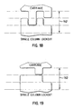
- Figs. 15 - 19 show examples of lockout when the overall length of aligned columns is three bit lengths 162 or four bit lengths 164 which both exceed the maximum of two bit lengths for matching compatibility.
- Figs. 14, 20A - 20C, and 21A - 21B all show examples of compatibility whcn the overall length of aligned columns is not more than two bit lengths 166.
- Figs. 21A - 21B By completely truncating all of the columns (Figs. 21A - 21B), none of the corresponding columns on any carriage are individually long enough to cause a lockout.
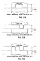
- Figs. 20A 20C When columns are partially truncated (Figs. 20A 20C), some universality is achieved where all corresponding columns on various carriages nave a length of one bit or less. This provides a way to prevent lockout of certain types of print cartridges having widespread use in many different printer carriages/chutes.
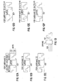
- Figs. 22-23 show a six column/four bit matrix using separate blocks to define the columns. Where the overall length of aligned columns is not more than three bit lengths 168, then compatible matchup occurs. When the overall length of aligned columns is four bit lengths 170, then lockout occurs since the maximum of three bit lengths has been exceeded.
- first bit position could be a slot, a second bit position a flat, and a third bit position a nub.
- a tab break-off design or machinable tab could be used such that a first bit position is “no tabs", a second bit position is “one tab” (or 1 ⁇ 2 height tab), and a third bit position is "two tabs" (or full height tab).
- the following table shows how the combination that yields the maximum number of unique keys is selected for a five position three bit embodiment.
Landscapes
- Ink Jet (AREA)
- Image Generation (AREA)
- Two-Way Televisions, Distribution Of Moving Picture Or The Like (AREA)
- Storage Device Security (AREA)
Abstract
Description
- This application is related to the following copending utility patent applications, each filed concurrently on January 5. 2000: Serial No.:
- by Ram Santhanam et al., entitled "Vent For An Ink-Jet Print Cartridge", attorney docket number 10992263-1; Serial No.: by Ram Santhanam et al., entitled "Ink-Jet Print Cartridge Having A Low Profile". attorney docket number 10992259-1; Serial No.: by Junji Yamamoto et al., entitled "Horizontally Loadable Carriage For An Ink-Jet Printer'. attorney docket number 10992261-1; Serial No.: by Junji Yamamoto et al., entitled-"Method And Apparatus For Horizontally Loading And Unloading An Ink-Jet Print Cartridge From A Carriage", attorney docket number 10992264-1; Serial No.: by Richard A. Becker et al., entitled "Techniques For Providing Ink-Jet Cartridges With A Universal Body Structure", attorney docket number 10992320-1; Serial No.:
- by Ram Santhanam et al., entitled "Techniques For Adapting A Small Form Factor Ink-Jet Cartridge For Use In A Carriage Sized For A Large Form Factor Cartridge", attorney docket number 10992260-1; Serial No.:
- by James M. Osmus, entitled "Printer With A Two Roller, Two Motor Paper Delivery System", attorney docket number 10001157-1; Serial No.:
- by Keng Leong Ng, entitled "Low Height Inkjet Service Station", attorney docket number 10001167-1; Serial No.: by Matt Shepherd et al., entitled "New Method Of Propelling An Inkjet Printer Carriage", attorney docket number 10001164-1; and Serial No.: by Ram Santhanam et al., entitled "Ink Jet Print Cartridge", attorney docket number 10001462-1, all of which are incorporated by reference.
-
- This invention relates generally to print cartridges mountable on printer carriages, and more specifically to mechanical techniques for preventing inkjet print cartridges from being used with non-compatible printers.
- The ability to ship and store print cartridges prior to installation on a printer has many benefits to the manufacturer, distributor and user. Similarly the life of a printer can be extended by providing removable print cartridges as well as replaceable print cartridges. However, the proliferation of such removable and replaceable print cartridges has created many problems arising from inadvertent use of similar appearing print cartridges in non-compatible printer carriages.
- Moreover the use of different types of inks, print media, and product implementations (facsimile machines, monochrome printers, color printers, copiers, multiple-function printers/fax/copiers, single chute carriages for holding different types of print cartridges, multiple chute carriages, cartridges capable of of carriage refill, cartridges capable of periodic on-carriage ink replenishment, continuous on-carriage ink replenishment systems) has created the need to differentiate between similar appearing print cartridges which have different intended uses.
- The problems of maintenance and warranty have also become aggravated when similar appearing print cartridges have been customized under joint development agreements for different end use implementations, some of which require mounting on standard carriages which move across a print zone while others are mounted alone or in groups on stationary carriages. Value added resellers want assurances that general use print cartridges outside of their control cannot be inadvertently used in their customized printing systems. In order to be able to provide some guarantee of quality, availability, warranty, maintenance and support, there is a growing need to uniquely identify print cartridges as well as to uniquely identify printer carriages and individual carriage chutes in a simple mechanical way. Electronic identification systems tend to be more expensive and are sometimes less reliable than mechanical encoding systems.
- Conventional label identification systems are extensively used but are often ignored by users and distributors, and even high visibility color coding of print cartridges has not provided satisfactory results.
- A prior mechanical technique is described in U.S. Patent 5,519,422 entitled METHOD AND DEVICE FOR PREVENTING UNINTENDED USE OF PRINT CARTRIDGES wherein a first level tab system controls initial insertion of a print cartridge, and a second level barrier system controls a final mounting step into a printer carriage. The implementation required different customized mechanical parts on two separate portions of the print cartridge as well as two corresponding separate portions of a carriage chute. Also there was a risk of tampering with the first level tabs by breaking them off in order to alter the ID system.
- Another prior mechanical technique has been employed by Lexmark which uses a rudimentary dual system where a large upstanding cap extending about one and one/half centimeters above the print cartridge has a central convex protrusion for one group of cartridges used in Xerox and Compaq printers and a central concave recess for another group of cartridges used in Lexmark printers. A second level of identification is provided with a pair of equally spaced apart narrow slots on the Xerox and Compaq print cartridges which are respectively located at different lateral positions relative to the central convex protrusion. Very few combinations are possible with this system, and it requires excessive space on both the print cartridge and the carriage.
- The present invention provides many combinations of LD for print cartridges and corresponding printer carriages and individual carriage chutes. A low profile pattern of columns which form a multiple bit matrix configuration is provided on a print cartridge and on its corresponding carriage. The columns are positioned to be contiguous for efficient use of space, and are capable of different lengths as measured from a default position.
- One embodiment incorporates separate blocks to define each bit position on a column, while another preferred embodiment provides a continuous contoured edge which moves back and forth depending on the matrix code which identifies a particular family of print cartridges (or carriages) as well as individual print cartridges (or carriages) within each family.
- Universal compatibility, family subset compatibility as well as unique one to one compatibility are possible with this multi-bit matrix scheme. The number of combinations can be expanded by either increasing the number of columns and/or by increasing the number of bit positions on a column. In a preferred form of the invention, the corresponding columns achieve complete matchup when the forward boundary of a print cartridge key matrix fits together with the forward boundary of a carriage key matrix.
- Compatibility is achieved by limiting the total combined length of one or more particular columns in the carriage and print cartridge key matrices, while lockout is achieved by increasing the total combined length of one or more particular columns in the carriage and print cartridge key matrices. Thus the rationale for achieving various different combinations which allow successful mounting of a print cartridge depends on controlling the pattern of the forward boundary of a key matrix as well as controlling the combined lengths of aligned columns in the carriage and print cartridge matrices.
- Unique differentiation between print cartridges is accomplished by having at least one column in a key matrix of a first print cartridge longer than a corresponding column in a key matrix of a second print cartridge.
- While the possible number of columns and column lengths (multiple position bits) in theory is endless, implementations in various embodiments of the invention include a five column three bit key matrix, an eight column three bit key matrix separated in the middle by a latch to provide a par of four column three bit key matrices, and a six column four bit key matrix.
-
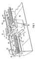
- Fig. 1 is a perspective view of a single chute carriage in a printer incorporating the invention, with a print cartridge mounted therein;
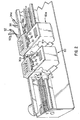
- Fig. 2 shows a double chute carriage in the printer of Fig. 1, with two print cartridges mounted therein;
- Fig. 3A is a perspective view of a print cartridge having a five column implementation of the invention using a key matrix formed with two rows of separate spaced-apart blocks;
- Fig. 3B is a top view schematic showing the five column implementation of Fig. 3A using two rows of separate contiguous blocks;
- Fig. 4 is a side view schematic showing the print cartridge of Fig. 3A with a biasing carriage spring engaging a print cartridge latch;
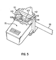
- Fig. 5 is a perspective view of the print cartridge of Fig. 3A mounted on a single chute carriage having a matching carriage key matrix formed with an exposed integral five column plate, without showing the biasing carriage spring;
- Fig. 6 is a fragmentary perspective view of an empty single chute carriage having a covered carriage key matrix, and showing the biasing carriage spring;
- Fig. 7 is a bottom view of the empty single chute of Fig. 6;
- Fig. 8 is a perspective view of a print cartridge having an eight column implementation of the invention using a low profile key matrix formed on both sides of a print cartridge latch;
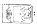
- Fig. 9 is a top plan view of the print cartridge of Fig. 8;
- Figs. 10A and 10B are schematic views looking up at two integral four column plates which together form a covered carriage key matrix having predetermined edge contours which match the low profile key matrix on the print cartridge of Figs. 8 and 9;
- Figs. 11A - 11F are schematic representations of exemplary print cartridge key patterns which respectively identify different print cartridge families;
- Figs. 12A - 12F are schematic representations of exemplary print cartridge key patterns of the single print cartridge family of Fig. 11A, with each key pattern being sufficiently different to be uniquely compatible with a particular printer carriage configuration;
- Fig. 13 is a schematic representation of an exemplary universal carriage key matrix capable of matchup with all print carridge key patterns of the print cartridge family of Figs. 12A - 12F;
- Fig. 14 schematically shows a four column matchup of key matrix patterns;
- Figs. 15 - 19 schematically show various lockout combinations of a four column key matrix pattern which occur when a print cartridge is inserted into a non-compatible printer carriage;
- Figs. 20A - 20C schematically show a hybrid print cartridge key matrix capable of matchup with a subset of different carriage key patterns;
- Figs. 21A and 21B schematically show a exemplary universal key matrix for a print cartridge capable of matchup with all carriage key patterns;
- Fig. 22 schematically shows a six column matchup of key matrix patterns; and
- Fig. 23 schematically shows a possible lockout combination of the six column key matrix patterns of Fig. 22 when a print cartridge is inserted into a non-compatible printer carriage.
-
- An exemplary printing mechanism as shown in Fig. 1 includes a
frame 30,support bar 32,angled guide bar 34,encoder strip 36, andcarriage drive motor 38. Acarriage member 40 has acylindrical bushing 42 which rides on thesupport bar 32 back and forth in acarriage scan direction 44 while media is periodically advanced along aplaten 46 in amedia advance direction 47 through a print zone. The carriage drive motor is mounted on a back of theframe 30 and carries adrive gear 48 coupled throughtransfer gear 50 tobelt gear 52 which engages an inside toothed surface of acarriage drive belt 54. The left end of the encoder strip is cut away to show the details of the carriage drive mechanisms. - In order to facilitate proper positioning of the carriage over the print zone, a
guide bracket 56 is attached at the top rear of thecarriage member 40 to slide along theangled guide bar 34. Aprint cartridge 60 is shown mounted on aabbreviated chute 61, and includes ahousing 62, andcap member 63 having right and left protrudingribs 64 and laterally extendinggrooves 66 for manual gripping during installation and removal of the print cartridge from the chute. Anozzle array 67 is located on a bottom surface of the print cartridge for applying ink drops to media on the platen. - The low profile of the cap member is an important feature of the invention (see Figs. 1 and 4), and the cap includes an upstanding
central latch 68 with adjacent key-codedprojections cap member 63.Space 75 is available on the cap for display of a company trademark or logo. Ametal biasing spring 76 extending from the chute presses its V-shapedend 78 downwardly against thecentral latch 68 and at an angle toward anelectrical interconnect 80 on the chute to provide conductive contact with aprint cartridge interconnect 82, without causing any interference with the key-codedprojections - The invention is applicable to single chute carriages (Fig. 1) as well as carriages having additional chutes for holding other identical print cartridges and well as other different types of print cartridges. Traditional carriages holding four print cartridges and high performance carriages holding eight, twelve and more print cartridges can also incorporate the benefits of the invention. A presently preferred embodiment for multiple print cartridges is shown in Fig. 2 with a first
tri-compartment print cartridge 60 holding cyan, magenta and yellow ink mounted inchute 61, alongside a blackink print cartridge 60a with similar external size specifications mounted inchute 61a. The key-coded projections onprint cartridge 60 are different from the key-coded projections onprint cartridge 60a to prevent using the print cartridges in the wrong chutes. - The
print cartridge 60 includes left and rightflex ribbon circuits encoder flex 90, whileprint cartridge 60a includessimilar flex components end terminals - One implementation of the key-coded projections on a print cartridge is shown in Figs. 3A, 4 and 5 which show a five column two
row matrix 100 extending across the entire front portion of the cap in front of the latch. While Fig. 3A showsblocks 102 spaced apart from blocks in adjacent rows and columns, a variation is shown in Fig. 3B withadjacent blocks 104 being contiguous. However the spaced apart block implementation makes it easier to create an encoded key pattern on a manufacturing line by selectively removing certain blocks without causing any damage to those blocks which remain to form the matrix pattern. When mounted in a compatible carriage chute 106 (see Fig. 5), a matching continuousedge matrix key 107 with some remaining blocks such as 108 and some blocks removed creates no lockout interference between any of the five alignedcolumns - Figs. 6 and 7 show more details of a preferred embodiment of a carriage chute key-coded pattern with the print cartridge removed. The pair of
continuous edge patterns protective plates 120. 122. Thedatum notches pivot legs spring 132 helps to secure the print cartridge. It is important to note that while lockout combinations of print cartridge and carriage key matrices allow both initial engagement of the side-biasingspring 132 with a print cartridge and the capturing of pivot legs by the datum notches, it is not until the V-shaped end of the metal biasing spring reaches its closed position against the latch on the print cartridge cap that a print cartridge achieves stable completed mounting and full conductive contact of the interconnects. The encoded key patterns are located so that such closed position of the metal biasing spring is prevented by abutting contact of aligned columns of non-compatible print cartridges and carriage chutes. - Figs. 8 and 9 show a presently preferred embodiment of a cap portion of a print cartridge with finger shaped
grooves 66a, and with a narrow centrally located latch having abeveled face 136 which raises the V-shaped end of the biasing spring upon initial engagement, an apex 138, and arecess 140 for receiving the V-shaped end in the absence of any lockout preventing completion of the mounting procedure. A separate key-coded projection 142 on one side of the latch hascontinuous edge 143 defined by fourcolumns continuous edge 149 defined by fouradditional columns Column # 144 145 146 147 150 151 152 153 Bit Position 3rd 1st 2nd 3rd 3rd 2nd 2nd 1st - Figs. 11A - 11F show a presently preferred implementation of
columns portion 155 for encoding different patterns of column lengths to identify each family of print cartridges. Of course the inverse bit positions for each column will provide the matching patterns, respectively, for all of the compatible printer carriages/chutes (see columns 144a, 145a and 146a in Fig. 10A). The pattern for Fig. 11B identifies die family of print cartridges shown in Figs. 8 and 9. - Figs. 12A - 12F show a presently preferred implementation of
columns columns - Comparative analysis of the matrix patterns of column locations 4 to 8 in Figs. 12A - 12F illustrate the technique of having at least one column in a key matrix of a first print cartridge longer than a corresponding column in a key matrix of a second print cartridge. Thus when considering the pattern in Fig. 12A shaped to match a key pattern of Carriage I, it is noted that lockout occurs because column #8 in Figs. 12B, 12C, 12E and 12F is longer than column #8 in Fig. 12A, and because column #6 in Figs. 12D, 12E, and 12F is longer than column #6 in Fig. 12A.
- Fig. 13 shows a pattern of completely truncated columns at 160, 161 in order to provide a universal carriage key for receiving all print cartridges of the family exemplified in Figs. 12A - 12F. A similar complete truncation of columns on a print cartridge creates a universal printhead key (see Figs. 21A and 21B) for installation on all carriages without causing any lockout.
- Figs. 15 - 19 show examples of lockout when the overall length of aligned columns is three
bit lengths 162 or fourbit lengths 164 which both exceed the maximum of two bit lengths for matching compatibility. - Figs. 14, 20A - 20C, and 21A - 21B all show examples of compatibility whcn the overall length of aligned columns is not more than two
bit lengths 166. By completely truncating all of the columns (Figs. 21A - 21B), none of the corresponding columns on any carriage are individually long enough to cause a lockout. When columns are partially truncated (Figs. 20A 20C), some universality is achieved where all corresponding columns on various carriages nave a length of one bit or less. This provides a way to prevent lockout of certain types of print cartridges having widespread use in many different printer carriages/chutes. - Finally, it will be understood upon reference to Figs. 22-23 that the invention is applicable to virtually all combinations of column/row sizes depending on the available space on a print cartridge. In that regard, Figs. 22-23 show a six column/four bit matrix using separate blocks to define the columns. Where the overall length of aligned columns is not more than three
bit lengths 168, then compatible matchup occurs. When the overall length of aligned columns is fourbit lengths 170, then lockout occurs since the maximum of three bit lengths has been exceeded. - There are other ways to define column lengths in order to implement the present invention. For example a first bit position could be a slot, a second bit position a flat, and a third bit position a nub. If there is a need for more easily configured keys, a tab break-off design or machinable tab could be used such that a first bit position is "no tabs", a second bit position is "one tab" (or ½ height tab), and a third bit position is "two tabs" (or full height tab).
- The following table shows how the combination that yields the maximum number of unique keys is selected for a five position three bit embodiment.
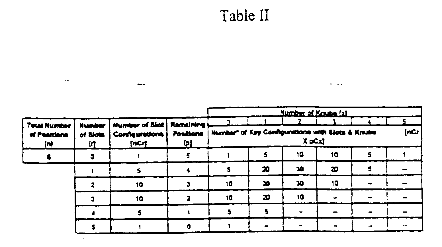
- As shown in Table II a scheme of "two nubs/two slots/one flat" or "two nub/one slot/ two flats" or "one nub/two slots/two flats each yield 30 unique combinations. Even though it appears that adding these combinations will increase the total number of configurations, some of them do not create the desired uniqueness required for lockout.
- Therefore although adding together the combinations of slot configurations will give us the theoretical maximum, the keys without the nubs will fit in the carriage designed to accept the keys with the nubs, hence making them unusable as unique keys.
- It is to be understood that the specific embodiments disclosed are by way of example only, and those skilled in the art will appreciate that various changes, improvements and modifications can be made to the examples given without departing from the spirit and scope of the invention as set forth in the following claims.
Claims (20)
- An inkjet print cartridge (60) which is mountable on a printer carriage, comprising:a housing (62);a printhead (67) on said housing;an ink reservoir in said housing and in communication with said printhead;an electrical interconnect (82) on said housing and coupled to said printhead for activating said printhead to eject ink;a latching component (68) on said housing for holding the print cartridge in a fully mounted position such that said electrical interconnect is in conductive engagement with a carriage interconnect (80); anda mechanical key (100, 104) on said housing formed into a predetermined pattern having a plurality of columns with each column capable of defining one or more multiple bit positions such that at least one of said columns acts as a barrier preventing the print cartridge from staying in the fully mounted position in certain non-compatible printer carriages.
- The print cartridge of claim 1 wherein said mechanical key includes: a predetermined pattern having a plurality of columns (144, 145, 146, 147) with each column capable of defining at least three different bit positions.
- The print cartridge of claim 2 wherein said plurality of columns includes three or more columns (144,145,146,147,150,151,152,153).
- The print cartridge of claim 1 wherein said mechanical key is formed into a predetermined pattern defined by upstanding blocks (102) which form said plurality of columns, with each block representing one bit of said multiple bit position.
- The print cartridge of claim 1 wherein said plurality of columns respectively include fixed ends at a default position and variable ends, and wherein said mechanical key is formed in a predetermined pattern defined by a boundary line along said variable ends.
- The print cartridge of claim 5 wherein said boundary line is formed by a continuous raised edge (143,149).
- An inkjet print cartridge (60, 60a) which is mountable on a printer carriage (40) having one or more chutes for holding the cartridge, comprising:a housing (62) with an ink reservoir therein, and having an outer surface;a nozzle member (67) on said outer surface and in communication with said ink reservoir and having an array of nozzles to eject ink;an electrical interconnect (82) on said housing for selectively activating said array of nozzles;a location datum (128,130) on said housing for engaging a chute (61) on a printer carriage (40) when the print cartridge is mounted in a printing position on the printer carriage;a latching component (68) on said outer surface of said housing for receiving a biasing member (76) on the printer carriage when the print cartridge is mounted in the printing position on the printer carriage; anda mechanical key (100,104) on said outer surface of said housing and formed by a predetermined pattern of multiple columns having forward ends which define a boundary, said boundary having a variable position depending a length of each of said multiple columns as measured from a default end of said columns.
- The print cartridge of claim 7 wherein said mechanical key includes a predetermined pattern which is formed by a matrix of multiple columns each having at least three different bit positions which define a length of the column, and wherein said pattern has a low profile extending less than five mm above said outer surface of said housing.
- The print cartridge of claim 7 wherein said mechanical key and said latching component are both located on a same side (63) of said outer surface of said housing.
- The print cartridge of claim 7 wherein at least one of said columns acts as a barrier preventing the print cartridge from being mounted in said printing position in a non-compatible chute of a printer carriage.
- The print cartridge of claim 7 wherein at least two of said columns act as a barrier preventing the print cartridge from being mounted in said printing position in a non-compatible chute of a printer carriage.
- The print cartridge of claim 7 which includes a supply of liquid ink in said ink reservoir.
- A carriage assembly for holding one or more inkjet print cartridges mounted thereon, comprising:a frame (30);a support member (40) on said frame;a chute (61) carried on said support member for holding the one or more print cartridges (60, 60a);an electrical interconnect (80) on said chute for coupling to said one or more print cartridges in order to selectively activate said print cartridges to eject in;a biasing member (76) on said chute for holding said one or more print cartridges in a secure mounted printing position; anda mechanical key (116, 118) on said chute formed into a predetermined pattern having a plurality of columns with each column capable of defining one or more multiple bit positions such that at least one of said columns acts as a barrier preventing a non-compatible print cartridge from staying in the secure mounted printing position.
- The carriage assembly of claim 13 wherein said mechanical key includes a predetermined pattern having a plurality of columns with each column capable of defining at least three different bit positions.
- The carriage assembly of claim 13 wherein said plurality of columns includes four or more columns.
- The carriage assembly of claim 13 wherein said plurality of columns respectively include fixed ends at a default position and variable ends, and wherein said mechanical key is formed in a predetermined pattern defined by a boundary line along said variable ends.
- The carriage assembly of claim 16 wherein said boundary line is formed by a continuous raised edge.
- The carriage assembly of claim 13 wherein at least one of said columns acts as a barrier preventing the print cartridge from being mounted in said printing position in a non-compatible chute of a printer carriage.
- The carriage assembly of claim 13 wherein at least two of said columns act as a barrier preventing the print cartridge from being mounted in said printing position in a non-compatible chute of a printer carriage.
- The carriage assembly of claim 13 which further includes a platen (46) for holding media passing through a print zone, and a mechanism (38) for moving said carriage back and forth over said platen.
Applications Claiming Priority (2)
| Application Number | Priority Date | Filing Date | Title |
|---|---|---|---|
| US09/477,940 US6290346B1 (en) | 2000-01-05 | 2000-01-05 | Multiple bit matrix configuration for key-latched printheads |
| US477940 | 2000-01-05 |
Publications (3)
| Publication Number | Publication Date |
|---|---|
| EP1114724A2 true EP1114724A2 (en) | 2001-07-11 |
| EP1114724A3 EP1114724A3 (en) | 2002-03-27 |
| EP1114724B1 EP1114724B1 (en) | 2008-02-13 |
Family
ID=23897937
Family Applications (1)
| Application Number | Title | Priority Date | Filing Date |
|---|---|---|---|
| EP00311366A Expired - Lifetime EP1114724B1 (en) | 2000-01-05 | 2000-12-19 | Multiple bit matrix configuration for key-latched printheads |
Country Status (6)
| Country | Link |
|---|---|
| US (3) | US6290346B1 (en) |
| EP (1) | EP1114724B1 (en) |
| JP (1) | JP2001191508A (en) |
| AT (1) | ATE385900T1 (en) |
| DE (1) | DE60038004T2 (en) |
| ES (1) | ES2296598T3 (en) |
Cited By (4)
| Publication number | Priority date | Publication date | Assignee | Title |
|---|---|---|---|---|
| EP1453018A1 (en) * | 2003-02-28 | 2004-09-01 | Nestec S.A. | Containers of flowable substance adapted for connecting to dispensing devices of a beverage or food dispensing machine |
| EP1844938A3 (en) * | 2006-04-12 | 2009-08-05 | Seiko Epson Corporation | Liquid container |
| CN103517809A (en) * | 2010-11-30 | 2014-01-15 | 惠普发展公司,有限责任合伙企业 | Fluid container having first and second key sets |
| EP3509849A4 (en) * | 2017-02-10 | 2020-05-06 | Hewlett-Packard Development Company, L.P. | MECHANICAL LOCKING MECHANISM FOR FLUID EJECTION |
Families Citing this family (37)
| Publication number | Priority date | Publication date | Assignee | Title |
|---|---|---|---|---|
| US6290346B1 (en) * | 2000-01-05 | 2001-09-18 | Hewlett-Packard Company | Multiple bit matrix configuration for key-latched printheads |
| ES2275603T5 (en) * | 2000-10-20 | 2010-07-07 | Seiko Epson Corporation | INJECTION RECORD DEVICE FOR INK AND INK CARTRIDGE. |
| PT1481808E (en) * | 2000-10-20 | 2007-02-28 | Seiko Epson Corp | Ink cartridge |
| US6654508B1 (en) * | 2000-11-27 | 2003-11-25 | Xerox Corporation | Correction and interpolation of position encoders |
| US6471333B1 (en) * | 2001-04-30 | 2002-10-29 | Hewlett-Packard Company | Method and apparatus for keying ink supply containers |
| USD457184S1 (en) | 2001-04-30 | 2002-05-14 | Hewlett-Packard Company | Ink jet print cartridge |
| USD464371S1 (en) | 2001-04-30 | 2002-10-15 | Hewlett-Packard Company | Ink jet print cartridge |
| US6729714B2 (en) * | 2001-07-31 | 2004-05-04 | Hewlett-Packard Development Company, L.P. | Separable key for establishing detachable printer component compatibility with a printer |
| US7585123B2 (en) * | 2001-08-22 | 2009-09-08 | Brother Kogyo Kabushiki Kaisha | Image forming apparatus |
| US6454387B1 (en) * | 2001-09-12 | 2002-09-24 | Hewlett-Packard Company | Capillary leak inhibitor for a print cartridge |
| US6652072B2 (en) * | 2001-09-28 | 2003-11-25 | Hewlett-Packard Development Company, L.P. | Interconnect circuit |
| JP4133154B2 (en) * | 2002-09-19 | 2008-08-13 | 株式会社リコー | Ink cartridge and inkjet printer |
| US6749294B2 (en) * | 2002-10-10 | 2004-06-15 | Hewlett-Packard Development Company, L.P. | Keying methods and apparatus for inkjet print cartridges and inkjet printers |
| US20050151807A1 (en) * | 2004-01-12 | 2005-07-14 | Nu-Kote International, Inc., A Corporation Of Delaware | Ink container for an ink jet cartridge |
| DE602005017350D1 (en) * | 2004-12-29 | 2009-12-10 | Oce Tech Bv | Printer with removable printhead |
| USD538335S1 (en) * | 2005-03-24 | 2007-03-13 | Microjet Technology Co., Ltd. | Cartridge |
| USD535326S1 (en) * | 2005-03-24 | 2007-01-16 | Microjet Technology Co., Ltd. | Cartridge |
| USD534582S1 (en) * | 2005-04-04 | 2007-01-02 | Canon Kabushiki Kaisha | Ink cartridge for printer |
| USD535688S1 (en) * | 2005-04-04 | 2007-01-23 | Canon Kabushiki Kaisha | Ink cartridge for printer |
| JP4632433B2 (en) | 2005-04-27 | 2011-02-16 | キヤノン株式会社 | Recording device |
| DE102006036716B3 (en) * | 2006-06-02 | 2007-09-27 | Artech Gmbh Design + Production In Plastic | Printer e.g. inkjet printer, retrofitting device, has cartridge retaining device to retain replaceable original ink cartridges, and locking pin to lock fastener in fastening position when insert-ink cartridge is attached in retaining device |
| USD571396S1 (en) * | 2007-01-23 | 2008-06-17 | Powerful Way Limited | Ink cartridge for computer printer |
| US8057006B2 (en) | 2007-10-24 | 2011-11-15 | Hewlett-Packard Development Company, L.P. | Fluid ejection device |
| US8382264B2 (en) * | 2008-01-25 | 2013-02-26 | Static Control Components, Inc. | Universal inkjet cartridge |
| US8397328B2 (en) * | 2008-07-01 | 2013-03-19 | Whirlpool Corporation | Apparatus and method for controlling concentration of wash aid in wash liquid |
| US8388695B2 (en) | 2008-07-01 | 2013-03-05 | Whirlpool Corporation | Apparatus and method for controlling laundering cycle by sensing wash aid concentration |
| US8266748B2 (en) * | 2008-07-01 | 2012-09-18 | Whirlpool Corporation | Apparatus and method for controlling bulk dispensing of wash aid by sensing wash aid concentration |
| WO2010134907A1 (en) | 2009-05-18 | 2010-11-25 | Hewlett-Packard Development Company, L.P. | Replaceable printing component |
| US8651645B2 (en) | 2010-10-29 | 2014-02-18 | Hewlett-Packard Development Company, L.P. | Print cartridge identification system and method |
| US8544994B2 (en) | 2010-12-28 | 2013-10-01 | Brother Kogyo Kabushiki Kaisha | Ink cartridge |
| JP5762028B2 (en) * | 2011-02-03 | 2015-08-12 | キヤノン株式会社 | Method for manufacturing liquid cartridge |
| CN105492210B (en) | 2013-06-28 | 2018-01-09 | 惠普发展公司,有限责任合伙企业 | Liquid ink box |
| WO2016018290A1 (en) * | 2014-07-30 | 2016-02-04 | Hewlett-Packard Development Company, L.P. | Preparing a printer cartridge for transport |
| JP6825286B2 (en) * | 2016-09-23 | 2021-02-03 | セイコーエプソン株式会社 | Liquid injection device |
| JP2019045595A (en) * | 2017-08-31 | 2019-03-22 | 京セラドキュメントソリューションズ株式会社 | Toner container, image forming apparatus |
| JP7392310B2 (en) * | 2019-07-25 | 2023-12-06 | 株式会社リコー | Head unit, printing device |
| JP2026018213A (en) * | 2024-07-25 | 2026-02-05 | 京セラドキュメントソリューションズ株式会社 | Image forming device |
Citations (1)
| Publication number | Priority date | Publication date | Assignee | Title |
|---|---|---|---|---|
| US5519422A (en) | 1993-05-03 | 1996-05-21 | Hewlett-Packard Company | Method and device for preventing unintended use of print cartridges |
Family Cites Families (52)
| Publication number | Priority date | Publication date | Assignee | Title |
|---|---|---|---|---|
| GB2127744B (en) | 1982-08-17 | 1986-07-02 | Canon Kk | Multicolour printing |
| US4740808A (en) | 1983-01-08 | 1988-04-26 | Canon Kabushiki Kaisha | Developer container and a developing apparatus usable with the same |
| US4611899A (en) | 1983-01-08 | 1986-09-16 | Canon Kabushiki Kaisha | Developing apparatus |
| JPS60107056A (en) | 1983-11-14 | 1985-06-12 | Sharp Corp | Developer replenishing device |
| US5870113A (en) * | 1984-03-31 | 1999-02-09 | Canon Kabushiki Kaisha | Liquid jet recording apparatus and method useable with removable recording head |
| JPS60219060A (en) | 1984-04-17 | 1985-11-01 | Canon Inc | liquid jet recording device |
| US4551734A (en) | 1984-12-06 | 1985-11-05 | Tektronix, Inc. | Ink cartridge with ink level sensor |
| JPS6266284A (en) | 1985-09-18 | 1987-03-25 | Minolta Camera Co Ltd | Toner cartridge device |
| US4739339A (en) | 1986-02-14 | 1988-04-19 | Dataproducts Corporation | Cartridge and method of using a cartridge for phase change ink in an ink jet apparatus |
| JPS63220186A (en) | 1987-03-10 | 1988-09-13 | Canon Inc | image forming device |
| JPH0720679Y2 (en) | 1988-03-01 | 1995-05-15 | 株式会社リコー | Toner supply device and toner cartridge thereof |
| US4853708A (en) | 1988-03-03 | 1989-08-01 | Eastman Kodak Company | Ink cartridge and housing construction for multicolor ink jet printing apparatus |
| JP2691914B2 (en) | 1988-09-09 | 1997-12-17 | 株式会社リコー | Image forming device |
| US4907019A (en) | 1989-03-27 | 1990-03-06 | Tektronix, Inc. | Ink jet cartridges and ink cartridge mounting system |
| JPH03184873A (en) | 1989-12-15 | 1991-08-12 | Canon Inc | Recorder |
| JP3222454B2 (en) | 1990-02-02 | 2001-10-29 | キヤノン株式会社 | Ink tank cartridge |
| JPH03269559A (en) | 1990-03-20 | 1991-12-02 | Mita Ind Co Ltd | Developer replenishing device |
| AU1812392A (en) | 1991-07-12 | 1993-01-14 | Minnesota Mining And Manufacturing Company | Bottle keying system |
| US5852458A (en) | 1991-08-27 | 1998-12-22 | Hewlett-Packard Company | Inkjet print cartridge having a first inlet port for initial filling and a second inlet port for ink replenishment without removing the print cartridge from the printer |
| US5406320A (en) | 1992-03-10 | 1995-04-11 | Scitex Digital Printing, Inc. | Ink replenishment assemblies for ink jet printers |
| US5408746A (en) | 1993-04-30 | 1995-04-25 | Hewlett-Packard Company | Datum formation for improved alignment of multiple nozzle members in a printer |
| US5646665A (en) * | 1993-04-30 | 1997-07-08 | Hewlett-Packard Company | Side biased datum scheme for inkjet cartridge and carriage |
| EP0622207B1 (en) | 1993-04-30 | 1999-06-02 | Hewlett-Packard Company | Common ink jet cartridge platform for different print heads |
| US5396316A (en) | 1993-10-20 | 1995-03-07 | Hewlett-Packard Company | User-replaceable liquid toner cartridge with integral pump and valve mechanisms |
| US5825387A (en) | 1995-04-27 | 1998-10-20 | Hewlett-Packard Company | Ink supply for an ink-jet printer |
| US6142617A (en) | 1995-04-27 | 2000-11-07 | Hewlett-Packard Company | Ink container configured for use with compact supply station |
| US5956057A (en) * | 1996-08-30 | 1999-09-21 | Hewlett-Packard Company | Ink container having electronic and mechanical features enabling plug compatibility between multiple supply sizes |
| JP3158915B2 (en) | 1994-12-27 | 2001-04-23 | ブラザー工業株式会社 | Mobile ink ejection device |
| US6130695A (en) * | 1995-04-27 | 2000-10-10 | Hewlett-Packard Company | Ink delivery system adapter |
| JPH0939265A (en) | 1995-07-29 | 1997-02-10 | Seiko Epson Corp | Ink cartridge and its identification device in printer |
| JP3280202B2 (en) | 1995-08-01 | 2002-04-30 | ブラザー工業株式会社 | Inkjet printer |
| US5880764A (en) | 1995-12-04 | 1999-03-09 | Hewlett-Packard Company | Adaptive ink supply for an ink-jet printer |
| DE69617610T2 (en) | 1995-12-04 | 2002-05-08 | Hewlett-Packard Co. (N.D.Ges.D.Staates Delaware), Palo Alto | Encoding device for ink supply containers |
| US6102517A (en) * | 1995-12-25 | 2000-08-15 | Seiko Epson Corporation | Ink-jet recording apparatus for ink cartridge |
| JP3363680B2 (en) | 1995-12-28 | 2003-01-08 | ブラザー工業株式会社 | Cartridge authenticity discrimination method and output device using the same |
| US5861903A (en) | 1996-03-07 | 1999-01-19 | Tektronix, Inc. | Ink feed system |
| DE69715529T2 (en) | 1996-06-27 | 2003-06-05 | Hewlett-Packard Co. (N.D.Ges.D.Staates Delaware), Palo Alto | Encoding device for ink supply containers |
| US5678121A (en) | 1996-07-01 | 1997-10-14 | Xerox Corporation | Document production machine having an orientation-independent cartridge discriminating system assembly |
| USD409236S (en) | 1997-02-26 | 1999-05-04 | Fuji Xerox Co., Ltd. | Ink tank for a printer |
| US5807005A (en) | 1997-05-12 | 1998-09-15 | Lexmark International, Inc. | Cartridge lockout system and method |
| US5857129A (en) | 1997-11-10 | 1999-01-05 | Xerox Corporation | Toner container with foolproof adaptor |
| DE19925419A1 (en) * | 1999-06-02 | 2000-12-07 | Voith Sulzer Papiertech Patent | Elastic roller and method of making it |
| US6227663B1 (en) * | 2000-01-05 | 2001-05-08 | Hewlett-Packard Company | Ink-jet print cartridge having a low profile |
| USD439925S1 (en) * | 2000-01-05 | 2001-04-03 | Hewlett-Packard Company | Ink jet print cartridge |
| US6332676B1 (en) * | 2000-01-05 | 2001-12-25 | Hewlett-Packard Company | Vent for an ink-jet print cartridge |
| US6540320B2 (en) * | 2000-01-05 | 2003-04-01 | Hewlett-Packard Company | Low-height ink jet service station |
| US6296345B1 (en) * | 2000-01-05 | 2001-10-02 | Hewlett-Packard Company | Method and apparatus for horizontally loading and unloading an ink-jet print cartridge from a carriage |
| US6293718B1 (en) * | 2000-01-05 | 2001-09-25 | Hewlett-Packard Company | Printer with a two roller, two motor paper delivery system |
| US6290348B1 (en) * | 2000-01-05 | 2001-09-18 | Hewlett-Packard Company | Techniques for providing ink-jet cartridges with a universal body structure |
| US6499826B1 (en) * | 2000-01-05 | 2002-12-31 | Hewlett-Packard Company | Horizontally loadable carriage for an ink-jet printer |
| US6290346B1 (en) * | 2000-01-05 | 2001-09-18 | Hewlett-Packard Company | Multiple bit matrix configuration for key-latched printheads |
| US6161920A (en) * | 2000-01-05 | 2000-12-19 | Hewlett-Packard Company | Techniques for adapting a small form factor ink-jet cartridge for use in a carriage sized for a large form factor cartridge |
-
2000
- 2000-01-05 US US09/477,940 patent/US6290346B1/en not_active Expired - Fee Related
- 2000-12-19 DE DE60038004T patent/DE60038004T2/en not_active Expired - Lifetime
- 2000-12-19 EP EP00311366A patent/EP1114724B1/en not_active Expired - Lifetime
- 2000-12-19 ES ES00311366T patent/ES2296598T3/en not_active Expired - Lifetime
- 2000-12-19 AT AT00311366T patent/ATE385900T1/en not_active IP Right Cessation
- 2000-12-28 JP JP2000400246A patent/JP2001191508A/en active Pending
-
2001
- 2001-04-27 US US09/844,346 patent/US6547378B2/en not_active Expired - Fee Related
- 2001-04-27 US US09/845,074 patent/US6568793B2/en not_active Expired - Fee Related
Patent Citations (1)
| Publication number | Priority date | Publication date | Assignee | Title |
|---|---|---|---|---|
| US5519422A (en) | 1993-05-03 | 1996-05-21 | Hewlett-Packard Company | Method and device for preventing unintended use of print cartridges |
Cited By (9)
| Publication number | Priority date | Publication date | Assignee | Title |
|---|---|---|---|---|
| EP1453018A1 (en) * | 2003-02-28 | 2004-09-01 | Nestec S.A. | Containers of flowable substance adapted for connecting to dispensing devices of a beverage or food dispensing machine |
| US6868988B2 (en) * | 2003-02-28 | 2005-03-22 | Nestec S.A. | Containers of flowable substance adapted for connecting to dispensing devices of a beverage or food dispensing machine |
| EP1844938A3 (en) * | 2006-04-12 | 2009-08-05 | Seiko Epson Corporation | Liquid container |
| US7967427B2 (en) | 2006-04-12 | 2011-06-28 | Seiko Epson Corporation | Liquid container |
| CN103517809A (en) * | 2010-11-30 | 2014-01-15 | 惠普发展公司,有限责任合伙企业 | Fluid container having first and second key sets |
| US9211720B2 (en) | 2010-11-30 | 2015-12-15 | Hewlett-Packard Development Company, L.P. | Fluid container having first and second key set |
| CN103517809B (en) * | 2010-11-30 | 2016-04-13 | 惠普发展公司,有限责任合伙企业 | Fluid container with first and second key sets |
| EP3509849A4 (en) * | 2017-02-10 | 2020-05-06 | Hewlett-Packard Development Company, L.P. | MECHANICAL LOCKING MECHANISM FOR FLUID EJECTION |
| US10864731B2 (en) | 2017-02-10 | 2020-12-15 | Hewlett-Packard Development Company, L.P. | Mechanical locking mechanism for fluid ejection |
Also Published As
| Publication number | Publication date |
|---|---|
| ES2296598T3 (en) | 2008-05-01 |
| DE60038004D1 (en) | 2008-03-27 |
| US6547378B2 (en) | 2003-04-15 |
| US20020039128A1 (en) | 2002-04-04 |
| EP1114724B1 (en) | 2008-02-13 |
| US6568793B2 (en) | 2003-05-27 |
| EP1114724A3 (en) | 2002-03-27 |
| JP2001191508A (en) | 2001-07-17 |
| US6290346B1 (en) | 2001-09-18 |
| ATE385900T1 (en) | 2008-03-15 |
| DE60038004T2 (en) | 2009-01-22 |
| HK1034933A1 (en) | 2001-11-09 |
| US20020041314A1 (en) | 2002-04-11 |
Similar Documents
| Publication | Publication Date | Title |
|---|---|---|
| EP1114724B1 (en) | Multiple bit matrix configuration for key-latched printheads | |
| EP0968090B1 (en) | Ink container having electronic and mechanical features enabling plug compatibility between multiple supply sizes | |
| EP1431042B1 (en) | Replaceable ink container for an inkjet printing system | |
| EP2107971B1 (en) | Combined ink family keying for an ink cartridge | |
| US6142617A (en) | Ink container configured for use with compact supply station | |
| EP0993954B1 (en) | Inkjet printing system using a modular print cartridge assembly | |
| EP0992348B1 (en) | Modular print cartridge receptacle for use in inkjet printing systems | |
| EP0900662B1 (en) | A storage container for inkjet cartridges having removable capping means and a method for storing inkjet cartridges | |
| US6027209A (en) | Ordered storage and/or removal of inkjet cartridges and capping means from a storage container | |
| EP1767370B1 (en) | Method of normality decision with regard to ink cartridge and printer actualizing the method | |
| KR100402568B1 (en) | Double Pen Carriage System | |
| KR100473960B1 (en) | Ink container configured for use with printer | |
| CN101808828A (en) | Ink cartridge holder | |
| HK1034933B (en) | Multiple bit matrix configuration for key-latched printheads | |
| US20120105519A1 (en) | Print cartridge identification system and method | |
| KR20030011700A (en) | Device for ensuring proper toe-heel installation of a detachable printer component | |
| JP4210983B2 (en) | Liquid ejector | |
| JPH08216429A (en) | Ink jet recording device | |
| KR19990010915U (en) | Ink cartridge combiner of inkjet printer | |
| HK1068011B (en) | Replaceable ink container for an inkjet printing system | |
| JP2006062247A (en) | Liquid storage tank and image forming apparatus equipped with the same | |
| HK1050876B (en) | Apparatus for keying ink supply containers | |
| HK1056145A1 (en) | Ink container for reliable electrical connection with a receiving station | |
| HK1050876A1 (en) | Apparatus for keying ink supply containers |
Legal Events
| Date | Code | Title | Description |
|---|---|---|---|
| PUAI | Public reference made under article 153(3) epc to a published international application that has entered the european phase |
Free format text: ORIGINAL CODE: 0009012 |
|
| AK | Designated contracting states |
Kind code of ref document: A2 Designated state(s): AT BE CH CY DE DK ES FI FR GB GR IE IT LI LU MC NL PT SE TR |
|
| AX | Request for extension of the european patent |
Free format text: AL;LT;LV;MK;RO;SI |
|
| PUAL | Search report despatched |
Free format text: ORIGINAL CODE: 0009013 |
|
| AK | Designated contracting states |
Kind code of ref document: A3 Designated state(s): AT BE CH CY DE DK ES FI FR GB GR IE IT LI LU MC NL PT SE TR |
|
| AX | Request for extension of the european patent |
Free format text: AL;LT;LV;MK;RO;SI |
|
| 17P | Request for examination filed |
Effective date: 20020910 |
|
| AKX | Designation fees paid |
Free format text: AT BE CH CY DE DK ES FI FR GB GR IE IT LI LU MC NL PT SE TR |
|
| 17Q | First examination report despatched |
Effective date: 20041118 |
|
| GRAP | Despatch of communication of intention to grant a patent |
Free format text: ORIGINAL CODE: EPIDOSNIGR1 |
|
| GRAS | Grant fee paid |
Free format text: ORIGINAL CODE: EPIDOSNIGR3 |
|
| GRAA | (expected) grant |
Free format text: ORIGINAL CODE: 0009210 |
|
| AK | Designated contracting states |
Kind code of ref document: B1 Designated state(s): AT BE CH CY DE DK ES FI FR GB GR IE IT LI LU MC NL PT SE TR |
|
| REG | Reference to a national code |
Ref country code: GB Ref legal event code: FG4D |
|
| REG | Reference to a national code |
Ref country code: CH Ref legal event code: EP |
|
| REG | Reference to a national code |
Ref country code: IE Ref legal event code: FG4D |
|
| REF | Corresponds to: |
Ref document number: 60038004 Country of ref document: DE Date of ref document: 20080327 Kind code of ref document: P |
|
| REG | Reference to a national code |
Ref country code: ES Ref legal event code: FG2A Ref document number: 2296598 Country of ref document: ES Kind code of ref document: T3 |
|
| REG | Reference to a national code |
Ref country code: HK Ref legal event code: GR Ref document number: 1034933 Country of ref document: HK |
|
| PG25 | Lapsed in a contracting state [announced via postgrant information from national office to epo] |
Ref country code: FI Free format text: LAPSE BECAUSE OF FAILURE TO SUBMIT A TRANSLATION OF THE DESCRIPTION OR TO PAY THE FEE WITHIN THE PRESCRIBED TIME-LIMIT Effective date: 20080213 |
|
| PG25 | Lapsed in a contracting state [announced via postgrant information from national office to epo] |
Ref country code: AT Free format text: LAPSE BECAUSE OF FAILURE TO SUBMIT A TRANSLATION OF THE DESCRIPTION OR TO PAY THE FEE WITHIN THE PRESCRIBED TIME-LIMIT Effective date: 20080213 |
|
| ET | Fr: translation filed | ||
| PG25 | Lapsed in a contracting state [announced via postgrant information from national office to epo] |
Ref country code: BE Free format text: LAPSE BECAUSE OF FAILURE TO SUBMIT A TRANSLATION OF THE DESCRIPTION OR TO PAY THE FEE WITHIN THE PRESCRIBED TIME-LIMIT Effective date: 20080213 |
|
| PG25 | Lapsed in a contracting state [announced via postgrant information from national office to epo] |
Ref country code: SE Free format text: LAPSE BECAUSE OF FAILURE TO SUBMIT A TRANSLATION OF THE DESCRIPTION OR TO PAY THE FEE WITHIN THE PRESCRIBED TIME-LIMIT Effective date: 20080513 Ref country code: DK Free format text: LAPSE BECAUSE OF FAILURE TO SUBMIT A TRANSLATION OF THE DESCRIPTION OR TO PAY THE FEE WITHIN THE PRESCRIBED TIME-LIMIT Effective date: 20080213 Ref country code: PT Free format text: LAPSE BECAUSE OF FAILURE TO SUBMIT A TRANSLATION OF THE DESCRIPTION OR TO PAY THE FEE WITHIN THE PRESCRIBED TIME-LIMIT Effective date: 20080714 |
|
| PLBE | No opposition filed within time limit |
Free format text: ORIGINAL CODE: 0009261 |
|
| STAA | Information on the status of an ep patent application or granted ep patent |
Free format text: STATUS: NO OPPOSITION FILED WITHIN TIME LIMIT |
|
| 26N | No opposition filed |
Effective date: 20081114 |
|
| PG25 | Lapsed in a contracting state [announced via postgrant information from national office to epo] |
Ref country code: CY Free format text: LAPSE BECAUSE OF FAILURE TO SUBMIT A TRANSLATION OF THE DESCRIPTION OR TO PAY THE FEE WITHIN THE PRESCRIBED TIME-LIMIT Effective date: 20080213 Ref country code: MC Free format text: LAPSE BECAUSE OF NON-PAYMENT OF DUE FEES Effective date: 20081231 |
|
| REG | Reference to a national code |
Ref country code: CH Ref legal event code: PL |
|
| PG25 | Lapsed in a contracting state [announced via postgrant information from national office to epo] |
Ref country code: LI Free format text: LAPSE BECAUSE OF NON-PAYMENT OF DUE FEES Effective date: 20081231 Ref country code: CH Free format text: LAPSE BECAUSE OF NON-PAYMENT OF DUE FEES Effective date: 20081231 Ref country code: IE Free format text: LAPSE BECAUSE OF NON-PAYMENT OF DUE FEES Effective date: 20081219 |
|
| PG25 | Lapsed in a contracting state [announced via postgrant information from national office to epo] |
Ref country code: LU Free format text: LAPSE BECAUSE OF NON-PAYMENT OF DUE FEES Effective date: 20081219 |
|
| PG25 | Lapsed in a contracting state [announced via postgrant information from national office to epo] |
Ref country code: TR Free format text: LAPSE BECAUSE OF FAILURE TO SUBMIT A TRANSLATION OF THE DESCRIPTION OR TO PAY THE FEE WITHIN THE PRESCRIBED TIME-LIMIT Effective date: 20080213 |
|
| PG25 | Lapsed in a contracting state [announced via postgrant information from national office to epo] |
Ref country code: GR Free format text: LAPSE BECAUSE OF FAILURE TO SUBMIT A TRANSLATION OF THE DESCRIPTION OR TO PAY THE FEE WITHIN THE PRESCRIBED TIME-LIMIT Effective date: 20080514 |
|
| REG | Reference to a national code |
Ref country code: GB Ref legal event code: 732E Free format text: REGISTERED BETWEEN 20120329 AND 20120404 |
|
| REG | Reference to a national code |
Ref country code: NL Ref legal event code: SD Effective date: 20120731 |
|
| REG | Reference to a national code |
Ref country code: ES Ref legal event code: PC2A Owner name: HEWLETT-PACKARD DEVELOPMENT COMPANY, L.P. Effective date: 20120911 |
|
| PGFP | Annual fee paid to national office [announced via postgrant information from national office to epo] |
Ref country code: GB Payment date: 20121227 Year of fee payment: 13 Ref country code: IT Payment date: 20121219 Year of fee payment: 13 |
|
| PGFP | Annual fee paid to national office [announced via postgrant information from national office to epo] |
Ref country code: FR Payment date: 20130110 Year of fee payment: 13 |
|
| PGFP | Annual fee paid to national office [announced via postgrant information from national office to epo] |
Ref country code: ES Payment date: 20121226 Year of fee payment: 13 Ref country code: DE Payment date: 20121231 Year of fee payment: 13 |
|
| PGFP | Annual fee paid to national office [announced via postgrant information from national office to epo] |
Ref country code: NL Payment date: 20121225 Year of fee payment: 13 |
|
| REG | Reference to a national code |
Ref country code: DE Ref legal event code: R119 Ref document number: 60038004 Country of ref document: DE |
|
| REG | Reference to a national code |
Ref country code: NL Ref legal event code: V1 Effective date: 20140701 |
|
| GBPC | Gb: european patent ceased through non-payment of renewal fee |
Effective date: 20131219 |
|
| REG | Reference to a national code |
Ref country code: FR Ref legal event code: ST Effective date: 20140829 |
|
| REG | Reference to a national code |
Ref country code: DE Ref legal event code: R119 Ref document number: 60038004 Country of ref document: DE Effective date: 20140701 |
|
| PG25 | Lapsed in a contracting state [announced via postgrant information from national office to epo] |
Ref country code: NL Free format text: LAPSE BECAUSE OF NON-PAYMENT OF DUE FEES Effective date: 20140701 Ref country code: DE Free format text: LAPSE BECAUSE OF NON-PAYMENT OF DUE FEES Effective date: 20140701 |
|
| PG25 | Lapsed in a contracting state [announced via postgrant information from national office to epo] |
Ref country code: GB Free format text: LAPSE BECAUSE OF NON-PAYMENT OF DUE FEES Effective date: 20131219 Ref country code: FR Free format text: LAPSE BECAUSE OF NON-PAYMENT OF DUE FEES Effective date: 20131231 |
|
| REG | Reference to a national code |
Ref country code: ES Ref legal event code: FD2A Effective date: 20150429 |
|
| PG25 | Lapsed in a contracting state [announced via postgrant information from national office to epo] |
Ref country code: ES Free format text: LAPSE BECAUSE OF NON-PAYMENT OF DUE FEES Effective date: 20131220 |
|
| PG25 | Lapsed in a contracting state [announced via postgrant information from national office to epo] |
Ref country code: IT Free format text: LAPSE BECAUSE OF NON-PAYMENT OF DUE FEES Effective date: 20131231 |
|
| PG25 | Lapsed in a contracting state [announced via postgrant information from national office to epo] |
Ref country code: IT Free format text: LAPSE BECAUSE OF NON-PAYMENT OF DUE FEES Effective date: 20131219 |