EP1114658B1 - Stange, insbesondere zum Begrenzen von Pisten - Google Patents
Stange, insbesondere zum Begrenzen von Pisten Download PDFInfo
- Publication number
- EP1114658B1 EP1114658B1 EP99830809A EP99830809A EP1114658B1 EP 1114658 B1 EP1114658 B1 EP 1114658B1 EP 99830809 A EP99830809 A EP 99830809A EP 99830809 A EP99830809 A EP 99830809A EP 1114658 B1 EP1114658 B1 EP 1114658B1
- Authority
- EP
- European Patent Office
- Prior art keywords
- post
- active portion
- anchoring
- pole
- presents
- Prior art date
- Legal status (The legal status is an assumption and is not a legal conclusion. Google has not performed a legal analysis and makes no representation as to the accuracy of the status listed.)
- Expired - Lifetime
Links
Images
Classifications
-
- A—HUMAN NECESSITIES
- A63—SPORTS; GAMES; AMUSEMENTS
- A63C—SKATES; SKIS; ROLLER SKATES; DESIGN OR LAYOUT OF COURTS, RINKS OR THE LIKE
- A63C19/00—Design or layout of playing courts, rinks, bowling greens or areas for water-skiing; Covers therefor
- A63C19/06—Apparatus for setting-out or dividing courts
- A63C19/062—Slalom gate poles, posts or marking sticks for sport fields
Definitions
- the present invention relates to a post for delimiting tracings, in particular for applications in the sporting field for delimiting tracks, supporting protections, defining paths dedicated to the amateur or professional practice of a sport; typical examples of applications in this field are found extensively in alpine skiing.
- posts that are widely employed in skiing facilities are made of plastic material or, more rarely, of wood; such posts are substantially shaped according to elongated forms, present an extremity suitable for being driven into the solid ground or into snow and can be used individually or in such a way as to constitute supports for safety nets.
- Other typical examples of such posts provide for their use as supports for signs or as border elements between areas devoted to sporting practice and areas devoted to other functions.
- the posts constructed according to known solutions present several drawbacks, particularly severe if one considers that an essential feature of the posts should be their guaranteeing users' safety.
- the post thus constructed will have dangerously low mechanical strength characteristics, so much so that in the impact it may easily break, often with the formation of splinters that are violently projected into the surrounding environment.
- the permanence of the post stub is an additional hazard, as it constitutes a typically sharp protuberance. This not only defeats its purpose, when it is to delimit or provide protection, but may lead to injuries caused by the splintered parts of the post.
- plastic is prone to a decay of its elastic properties, so that the application of a load nominally withstood by the post could cause its permanent warping under particularly adverse environmental conditions.
- a different type of delimiting post is available on the market, and it finds particular use in routes for alpine skiing competitions.
- a particular type of post is currently used, made of plastic, having tubular section and provided in its portion proximate to the ground with a ball joint, generally made of silicone resin.
- the joint allows the lowering of the part of post emerging from the ground by athletes who impact thereon when skirting the post itself.
- the first problem of such a construction is, yet again, safety.
- the athlete is subjected to a hard impact against the rigid material of the post; in the second place, the skier who has lowered it can be violently hit by the post as it returns upright, given that the elastic element concentrated in a single point close to the ground causes the rigid portion of the post to return violently, with considerable problems connected to the reactive impact of the post on the athlete's body.
- These facts today force slalom specialists to wear protections for all their limbs, their head and their teeth.
- such a post presents considerable costs and constructive complexity, being constituted by a multiplicity of elements such as a ground anchoring body, a ball joint and an upper portion projecting from the ground.
- the fundamental aim of the present invention is to provide a new post able substantially to solve all the drawbacks mentioned previously.
- a particular aim of the present invention is to provide a post with an extremely advantageous elastic behaviour in case of impact, i.e. able to provide adequate damping capabilities whilst maintaining a substantial structural integrity.
- a further aim of the present invention consists of obtaining a post of considerable constructive simplicity, in terms of complexity and overall number of elements required.
- an aim of the present invention consists of enabling to obtain a post that is free of the phenomena of decay in mechanical characteristics in low-temperature environments.
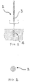
- the post according to the invention is globally indicated with the number 1.
- pole-like body 2 made of composite material; in reference to the described embodiments it is important to note that the composite material employed in the construction of this pole-like body 2 has its mechanically resisting fibres continuous, and substantially arranged along the axis of development of the pole-like body 2 itself. Delving in further detail, the fact should be stressed that the reinforcing fibres extend over the entire length of the pole-like body 2.
- the reason for this structural choice advantageously resides in the fact that such a configuration is able to offer a homogeneous elastic behaviour to the entire pole-like body 2; in other words the pole-like body 2 simultaneously serves as a structural core and as an elastic element for the post 1 according to the present invention.
- the selection of composite material with which to manufacture the pole-like element 2 is dictated by the usual engineering and cost considerations; in particular, one can choose to manufacture the pole-like body 2 with fibreglass, but if circumstances so require, materials with more advanced mechanical characteristics can be adopted, such as aramid fibre compounds (i.e. Kevlar) or carbon fibre based composites.
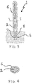
- the pole-like is formally divided into an active portion 3, which with the post 1 in the installed condition emerges from the ground and an anchoring portion 4 which on the contrary is buried when the post 1 is installed in the appropriate areas of the tracing to be delimited: with particular reference to Figures 1 and 3, one can note that the active portion and the anchoring portion 4 are mutually connected without interruption, and at the same time the composite material with which the pole-like body 2 is constructed guarantees the elasticity of this connection.
- the active portion 3 is tasked with absorbing the kinetic energy of a body which may impact against the post, whereas the anchoring portion 4 operates in such a way as to maintain the post 1 secured to the ground especially during the occurrence of the impact itself; lastly, one should consider the fact that the pole-like body is designed to confer a sufficiently elastic behaviour to the entire structure of the post 1 according to the present invention to avoid causing serious injuries or damage to the impacting body while maintaining the structural soundness of the post after the impact.
- the pole-like body 2 presents a geometrically identical section along the entire axis of development and this section is preferably shaped according to an axially symmetrical figure.
- the reason why the section of the pole-like body 2, with particular attention to the section of the active portion 3, should preferably be axially symmetrical resides in the fact that the post 1 according to the present invention must offer the same dynamic behaviour in case of impact in an undifferentiated manner according to all possible directions of incidence of the impact; in this view, as noted in Figure 2, the section of the pole-like body 2 advantageously has circular or slightly elliptical shape, but in case of given design and/or functional specifications the pole-like body 2 presents a solid structure.
- the pole-like body 2 can be manufactured with constant measures of the section along the entire axis of longitudinal development or can have variable cross section measurements; in particular, a pole-like body 2 can be obtained which presents at least the active portion 3 tapered, with growing section proceeding from the top of the post towards the ground.
- pole-like body in two or more successive portions with geometrically differentiated section: for instance a body comprising a segment with circular section and then a segment with elliptical section.
- the pole-like body 2 is suitable for being manufactured by profiling, given its simple geometric configuration; with particular reference to the employment of the composite material mentioned above (fibreglass), said pole-like body 2 is conveniently manufactured with the industrial process of pultrusion.
- Accessories can be associated to the pole-like body 2 to improve the functionality of the post 1 in terms of easing the installation of the post 1 itself and to improve the ability to reduce the severity of the damage to any bodies which may impact it.
- an anchoring element 5 associated to the anchoring portion 4 for instance by means of gluing; said anchoring body 5 is conveniently made of plastic material, and presents an inner cavity 7 destined to house at least partially the anchoring portion 4 (with reference to Figure 3, note that said inner cavity 7 is substantially counter-shaped relative to the anchoring portion 4), whilst on its own outer surface it houses friction means 8 destined to enhance the stability of the insertion of the post 1 into the ground; said friction means 8 are obtained by means of a projecting thread, which advantageously allows to insert the post 1 into the ground as if it were a self-threading screw.
- the function of the exterior coating 6 substantially consists of dampening the effects of the impact on the delicate parts of the impacting body whilst preventing the hazardous ejection of splinters in case of an unfortunate sudden rupture of the pole-like body 2 as a result of the impact the exterior coating 6 presents substantially cylindrical shape closed at one extremity and has an interior cavity shaped substantially counter to the active portion 3; the exterior coating 6 is mounted on the pole-like body 2 simply by fitting the exterior coating 6 on the active portion 3, so that the active portion 3 itself is housed in the inner cavity of the exterior coating 6.
- the invention achieves important advantages.
- pole-like body 2 provides the entire post 1 with a much greater ability to absorb impacts than known posts, because of the intrinsic elasticity of the composite material and thanks to the fact that the elastic properties are distributed along the entire pole-like body 2 and not concentrated in a limited area.
- a further advantage deriving from the use of composite material resides in the fact that this category of materials in practice is not affected in terms of degradation of its mechanical characteristics as a result of prolonged exposure to low temperatures.
- Yet another advantage is the extreme simplicity of construction of the post according to the present invention, which substantially guarantees elasticity without having to introduce elastic joints into the structure or divide the structure itself into multiple parts manufactured separately and then interconnected; this leads to significant benefits in regard to production times.
Landscapes
- Engineering & Computer Science (AREA)
- Architecture (AREA)
- Civil Engineering (AREA)
- Structural Engineering (AREA)
- Joining Of Building Structures In Genera (AREA)
- Vibration Dampers (AREA)
- Shafts, Cranks, Connecting Bars, And Related Bearings (AREA)
- Rolls And Other Rotary Bodies (AREA)
- Refuge Islands, Traffic Blockers, Or Guard Fence (AREA)
- Piles And Underground Anchors (AREA)
Claims (21)
- Stange, insbesondere zum Begrenzen von Pisten, umfassend einen stangenartigen Körper (2), wobei der stangenartige Körper (2) der Form nach unterteilt ist in:dadurch gekennzeichnet, dass der stangenartige Körper (2) einen festen Teil aufweist, der längs der gesamten Abwicklungsachse des stangenartigen Körpers (2) selbst konstant ist, wobei der feste Teil vollständig mit einer plastischen Matrize ausgeführt ist, in der eine Vielzahl von kontinuierlichen Verstärkungsfasern eingebettet ist.einen aktiven Abschnitt, verlängerter Ausbildung; undeinen am Boden befestigbaren Verankerungsabschnitt (4), der mit dem aktiven Abschnitt (3) verbunden ist;
- Stange nach Anspruch 1, dadurch gekennzeichnet, dass sie einen stangenförmigen Körper (2) aufweist, der den aktiven Abschnitt (3) und den Verankerungsabschnitt (4) umfasst, wobei der Verankerungsabschnitt (4) mit dem aktiven Abschnitt (3) elastisch verbunden ist, wobei der Verankerungsabschnitt (4) eine ununterbrochene Fortsetzung des aktiven Abschnittes (3) ist.
- Stange nach einem der vorstehenden Ansprüche, dadurch gekennzeichnet, dass die Verstärkungsfasern kontinuierlicher Art sind.
- Stange nach Anspruch 3, dadurch gekennzeichnet, dass die Fasern gemäß der Längsabwicklungsachse der Stange (1), bevorzugter Weise parallel zu dieser Achse angeordnet sind.
- Stange nach Anspruch 3, dadurch gekennzeichnet, dass sich die Fasern längs der gesamten Länge des aktiven Abschnittes (3) erstrecken.
- Stange nach einem beliebigen der vorstehenden Ansprüche, dadurch gekennzeichnet, dass die Verstärkungsfasern aus Glas und/oder Aramidfasern und/oder Kohlenstoff bestehen.
- Stange nach einem beliebigen der vorstehenden Ansprüche, dadurch gekennzeichnet, dass der Verankerungsabschnitt (4) mit einer Plastikmatrize ausgeführt ist, in der eine Vielzahl von Verstärkungsfasern eingebettet ist.
- Stange nach einem beliebigen der vorstehenden Ansprüche, dadurch gekennzeichnet, dass sie ein Verankerungselement (5) umfasst, das endseitig dem Verankerungsabschnitt (4) zugeordnet ist.
- Stange nach Anspruch 8, dadurch gekennzeichnet, dass das Verankerungselement (5) am Verankerungsabschnitt (4) der Stange (1) angeklebt ist.
- Stange nach Anspruch 8, dadurch gekennzeichnet, dass das Verankerungselement (5) einen Innenhohlraum (7), der mindestens einen Teil des Verankerungsabschnittes (4) aufnimmt, und eine den Körper begrenzende Außenfläche aufweist, wobei das Verankerungselement (5) dem Verankerungsabschnitt (4) durch Einbringen des Verankerungsabschnittes (4) in den Innenhohlraum (7) zugeordnet ist.
- Stange nach Anspruch 10, dadurch gekennzeichnet, dass das Verankerungselement (5) an einer Außenfläche Reibmittel (8) aufweist, um die Griffigkeit mit dem Boden zu erhöhen.
- Stange nach Anspruch 11, dadurch gekennzeichnet, dass die Reibungsmittel (8) ein an der genannten Außenfläche ausgenommenes Gewinde umfassen.
- Stange nach einem beliebigen der vorstehenden Ansprüche, dadurch gekennzeichnet, dass der aktive Abschnitt (3) einen Querschnitt aufweist, der gegenüber der Abwicklungsachse axialsymmetrisch ist.
- Stange nach Anspruch 13, dadurch gekennzeichnet, dass der aktive Abschnitt (3) einen kreisförmigen Querschnitt aufweist.
- Stange nach einem beliebigen der vorstehenden Ansprüche von 2 bis 14, dadurch gekennzeichnet, dass der stangenartige Körper (2) einen längs der Längsabwicklungsachse veränderlichen Querschnitt aufweist, wobei der stangenartige Körper (2) bevorzugter Weise vom Boden weg verjüngt ist.
- Stange nach einem beliebigen der vorstehenden Ansprüche, dadurch gekennzeichnet, dass der Axialkörper (2) durch formgebende Bearbeitung erhalten wird.
- Stange nach Anspruch 16, dadurch gekennzeichnet, dass der Axialkörper (2) durch Pultrusion erhalten wird.
- Stange nach einem beliebigen der vorstehenden Ansprüche, dadurch gekennzeichnet, dass sie eine Außenverkleidung (6) aufweist, die am aktiven Abschnitt (3) auswechselbar angreift, und dazu bestimmt ist, die Stoßwirkungen eines Körpers gegen die Stange (1) abzuschwächen.
- Stange nach Anspruch 18, dadurch gekennzeichnet, dass die Außenverkleidung (6) ein Längskörper ist, der einen Innenhohlraum aufweist, der mindestens einen Teil des aktiven Abschnittes (3) aufnimmt, wobei die Außenverkleidung (6) dem aktiven Abschnitt (3) durch Einbringen des aktiven Abschnittes (3) in den Innenhohlraum der Außenverkleidung (6) zugeordnet ist.
- Stange nach Anspruch 19, dadurch gekennzeichnet, dass der Innenhohlraum der Außenverkleidung (6) dem Teil des aktiven Abschnittes (3) gegenprofiliert ist, dem er zugeordnet ist.
- Stange nach Anspruch 18, dadurch gekennzeichnet, dass die Außenverkleidung (6) aus geschäumtem Polyurethan besteht.
Priority Applications (3)
| Application Number | Priority Date | Filing Date | Title |
|---|---|---|---|
| EP99830809A EP1114658B1 (de) | 1999-12-29 | 1999-12-29 | Stange, insbesondere zum Begrenzen von Pisten |
| DE69925137T DE69925137D1 (de) | 1999-12-29 | 1999-12-29 | Stange, insbesondere zum Begrenzen von Pisten |
| AT99830809T ATE294622T1 (de) | 1999-12-29 | 1999-12-29 | Stange, insbesondere zum begrenzen von pisten |
Applications Claiming Priority (1)
| Application Number | Priority Date | Filing Date | Title |
|---|---|---|---|
| EP99830809A EP1114658B1 (de) | 1999-12-29 | 1999-12-29 | Stange, insbesondere zum Begrenzen von Pisten |
Publications (2)
| Publication Number | Publication Date |
|---|---|
| EP1114658A1 EP1114658A1 (de) | 2001-07-11 |
| EP1114658B1 true EP1114658B1 (de) | 2005-05-04 |
Family
ID=8243731
Family Applications (1)
| Application Number | Title | Priority Date | Filing Date |
|---|---|---|---|
| EP99830809A Expired - Lifetime EP1114658B1 (de) | 1999-12-29 | 1999-12-29 | Stange, insbesondere zum Begrenzen von Pisten |
Country Status (3)
| Country | Link |
|---|---|
| EP (1) | EP1114658B1 (de) |
| AT (1) | ATE294622T1 (de) |
| DE (1) | DE69925137D1 (de) |
Families Citing this family (1)
| Publication number | Priority date | Publication date | Assignee | Title |
|---|---|---|---|---|
| IT1392334B1 (it) * | 2008-12-19 | 2012-02-28 | Parigi | Puntale per palo da sci e procedimento per il suo fissaggio al manto nevoso |
Family Cites Families (4)
| Publication number | Priority date | Publication date | Assignee | Title |
|---|---|---|---|---|
| US3279133A (en) * | 1964-08-18 | 1966-10-18 | Korte John F De | Boundary marker |
| FR2029174A5 (de) * | 1969-01-14 | 1970-10-16 | Favre Bernard | |
| AT382523B (de) * | 1983-11-18 | 1987-03-10 | Ims Kunststoff Gmbh | Ski-kipptorstange |
| IT220298Z2 (it) * | 1990-11-21 | 1993-09-16 | S P M | Palo snodato per piste da sci, con la parte fuoriterra in materiale morbido. |
-
1999
- 1999-12-29 AT AT99830809T patent/ATE294622T1/de not_active IP Right Cessation
- 1999-12-29 EP EP99830809A patent/EP1114658B1/de not_active Expired - Lifetime
- 1999-12-29 DE DE69925137T patent/DE69925137D1/de not_active Expired - Lifetime
Also Published As
| Publication number | Publication date |
|---|---|
| DE69925137D1 (de) | 2005-06-09 |
| ATE294622T1 (de) | 2005-05-15 |
| EP1114658A1 (de) | 2001-07-11 |
Similar Documents
| Publication | Publication Date | Title |
|---|---|---|
| US5050878A (en) | Hockey stick made of composite materials and its manufacturing process | |
| US5713082A (en) | Sports helmet | |
| US20080163410A1 (en) | Shock-absorbing facemask attachment assembly | |
| US6905429B2 (en) | Baseball bat with replaceable barrel | |
| US8747261B2 (en) | Reinforced objects | |
| KR102638299B1 (ko) | 파크골프채 | |
| EP1114658A1 (de) | Stange, insbesondere zum Begrenzen von Pisten | |
| CA2237292A1 (en) | Adjustable ball backstop | |
| US20110041227A1 (en) | Protective gear | |
| CA2293950A1 (en) | Improvement on hockey stick | |
| CN1050063C (zh) | 打击工具 | |
| CN215461891U (zh) | 一种高强度碳纤维羽毛球拍 | |
| CN209005158U (zh) | 一种学生用体育网球拍 | |
| US20050181897A1 (en) | Blade member | |
| FR2749519B1 (fr) | Complexe de recouvrement pour planche de glisse | |
| WO2007063068A1 (en) | Roller ski | |
| RU2852040C1 (ru) | Палочка гимнастической ленты | |
| EP1810730B1 (de) | Verstärkte Gelenkstange für Schipisten | |
| IT9022155U1 (it) | Palo snodato per piste da sci, con la parte fuoriterra in materiale mo rbido. | |
| CN218165914U (zh) | 一种防震性球拍 | |
| CN215084766U (zh) | 玄武岩纤维滑雪板 | |
| CA2148386A1 (en) | Sleeve for hockey stick | |
| KR960002664Y1 (ko) | 스포츠 라켓 | |
| CN1148513A (zh) | 网球拍 | |
| JPS5831578Y2 (ja) | スキ−ストツク |
Legal Events
| Date | Code | Title | Description |
|---|---|---|---|
| PUAI | Public reference made under article 153(3) epc to a published international application that has entered the european phase |
Free format text: ORIGINAL CODE: 0009012 |
|
| 17P | Request for examination filed |
Effective date: 20000919 |
|
| AK | Designated contracting states |
Kind code of ref document: A1 Designated state(s): AT BE CH CY DE DK ES FI FR GB GR IE IT LI LU MC NL PT SE |
|
| AX | Request for extension of the european patent |
Free format text: AL;LT;LV;MK;RO;SI |
|
| AKX | Designation fees paid |
Free format text: AT BE CH CY DE DK ES FI FR GB GR IE IT LI LU MC NL PT SE |
|
| AXX | Extension fees paid |
Free format text: SI PAYMENT 20011214 |
|
| 17Q | First examination report despatched |
Effective date: 20030407 |
|
| GRAP | Despatch of communication of intention to grant a patent |
Free format text: ORIGINAL CODE: EPIDOSNIGR1 |
|
| GRAS | Grant fee paid |
Free format text: ORIGINAL CODE: EPIDOSNIGR3 |
|
| GRAA | (expected) grant |
Free format text: ORIGINAL CODE: 0009210 |
|
| AK | Designated contracting states |
Kind code of ref document: B1 Designated state(s): AT BE CH CY DE DK ES FI FR GB GR IE IT LI LU MC NL PT SE |
|
| AX | Request for extension of the european patent |
Extension state: SI |
|
| PG25 | Lapsed in a contracting state [announced via postgrant information from national office to epo] |
Ref country code: NL Free format text: LAPSE BECAUSE OF FAILURE TO SUBMIT A TRANSLATION OF THE DESCRIPTION OR TO PAY THE FEE WITHIN THE PRESCRIBED TIME-LIMIT Effective date: 20050504 Ref country code: FI Free format text: LAPSE BECAUSE OF FAILURE TO SUBMIT A TRANSLATION OF THE DESCRIPTION OR TO PAY THE FEE WITHIN THE PRESCRIBED TIME-LIMIT Effective date: 20050504 Ref country code: BE Free format text: LAPSE BECAUSE OF FAILURE TO SUBMIT A TRANSLATION OF THE DESCRIPTION OR TO PAY THE FEE WITHIN THE PRESCRIBED TIME-LIMIT Effective date: 20050504 |
|
| REG | Reference to a national code |
Ref country code: GB Ref legal event code: FG4D |
|
| REG | Reference to a national code |
Ref country code: CH Ref legal event code: EP |
|
| REG | Reference to a national code |
Ref country code: IE Ref legal event code: FG4D |
|
| REF | Corresponds to: |
Ref document number: 69925137 Country of ref document: DE Date of ref document: 20050609 Kind code of ref document: P |
|
| RAP2 | Party data changed (patent owner data changed or rights of a patent transferred) |
Owner name: TOP GLASS S.P.A. |
|
| REG | Reference to a national code |
Ref country code: CH Ref legal event code: NV Representative=s name: ISLER & PEDRAZZINI AG |
|
| PG25 | Lapsed in a contracting state [announced via postgrant information from national office to epo] |
Ref country code: SE Free format text: LAPSE BECAUSE OF FAILURE TO SUBMIT A TRANSLATION OF THE DESCRIPTION OR TO PAY THE FEE WITHIN THE PRESCRIBED TIME-LIMIT Effective date: 20050804 Ref country code: GR Free format text: LAPSE BECAUSE OF FAILURE TO SUBMIT A TRANSLATION OF THE DESCRIPTION OR TO PAY THE FEE WITHIN THE PRESCRIBED TIME-LIMIT Effective date: 20050804 Ref country code: DK Free format text: LAPSE BECAUSE OF FAILURE TO SUBMIT A TRANSLATION OF THE DESCRIPTION OR TO PAY THE FEE WITHIN THE PRESCRIBED TIME-LIMIT Effective date: 20050804 |
|
| PG25 | Lapsed in a contracting state [announced via postgrant information from national office to epo] |
Ref country code: DE Free format text: LAPSE BECAUSE OF FAILURE TO SUBMIT A TRANSLATION OF THE DESCRIPTION OR TO PAY THE FEE WITHIN THE PRESCRIBED TIME-LIMIT Effective date: 20050805 |
|
| PG25 | Lapsed in a contracting state [announced via postgrant information from national office to epo] |
Ref country code: ES Free format text: LAPSE BECAUSE OF FAILURE TO SUBMIT A TRANSLATION OF THE DESCRIPTION OR TO PAY THE FEE WITHIN THE PRESCRIBED TIME-LIMIT Effective date: 20050815 |
|
| NLT2 | Nl: modifications (of names), taken from the european patent patent bulletin |
Owner name: TOP GLASS S.P.A. Effective date: 20050629 |
|
| PG25 | Lapsed in a contracting state [announced via postgrant information from national office to epo] |
Ref country code: PT Free format text: LAPSE BECAUSE OF FAILURE TO SUBMIT A TRANSLATION OF THE DESCRIPTION OR TO PAY THE FEE WITHIN THE PRESCRIBED TIME-LIMIT Effective date: 20051017 |
|
| NLV1 | Nl: lapsed or annulled due to failure to fulfill the requirements of art. 29p and 29m of the patents act | ||
| PG25 | Lapsed in a contracting state [announced via postgrant information from national office to epo] |
Ref country code: IE Free format text: LAPSE BECAUSE OF NON-PAYMENT OF DUE FEES Effective date: 20051229 Ref country code: GB Free format text: LAPSE BECAUSE OF NON-PAYMENT OF DUE FEES Effective date: 20051229 Ref country code: CY Free format text: LAPSE BECAUSE OF FAILURE TO SUBMIT A TRANSLATION OF THE DESCRIPTION OR TO PAY THE FEE WITHIN THE PRESCRIBED TIME-LIMIT Effective date: 20051229 |
|
| PG25 | Lapsed in a contracting state [announced via postgrant information from national office to epo] |
Ref country code: MC Free format text: LAPSE BECAUSE OF NON-PAYMENT OF DUE FEES Effective date: 20051231 Ref country code: LU Free format text: LAPSE BECAUSE OF NON-PAYMENT OF DUE FEES Effective date: 20051231 |
|
| PLBE | No opposition filed within time limit |
Free format text: ORIGINAL CODE: 0009261 |
|
| STAA | Information on the status of an ep patent application or granted ep patent |
Free format text: STATUS: NO OPPOSITION FILED WITHIN TIME LIMIT |
|
| ET | Fr: translation filed | ||
| 26N | No opposition filed |
Effective date: 20060207 |
|
| GBPC | Gb: european patent ceased through non-payment of renewal fee |
Effective date: 20051229 |
|
| REG | Reference to a national code |
Ref country code: IE Ref legal event code: MM4A |
|
| REG | Reference to a national code |
Ref country code: CH Ref legal event code: PCAR Free format text: ISLER & PEDRAZZINI AG;POSTFACH 1772;8027 ZUERICH (CH) |
|
| PGFP | Annual fee paid to national office [announced via postgrant information from national office to epo] |
Ref country code: AT Payment date: 20071224 Year of fee payment: 9 Ref country code: CH Payment date: 20071224 Year of fee payment: 9 Ref country code: IT Payment date: 20071222 Year of fee payment: 9 |
|
| PGFP | Annual fee paid to national office [announced via postgrant information from national office to epo] |
Ref country code: FR Payment date: 20071220 Year of fee payment: 9 |
|
| REG | Reference to a national code |
Ref country code: CH Ref legal event code: PL |
|
| PG25 | Lapsed in a contracting state [announced via postgrant information from national office to epo] |
Ref country code: AT Free format text: LAPSE BECAUSE OF NON-PAYMENT OF DUE FEES Effective date: 20081229 |
|
| REG | Reference to a national code |
Ref country code: FR Ref legal event code: ST Effective date: 20090831 |
|
| PG25 | Lapsed in a contracting state [announced via postgrant information from national office to epo] |
Ref country code: LI Free format text: LAPSE BECAUSE OF NON-PAYMENT OF DUE FEES Effective date: 20081231 Ref country code: CH Free format text: LAPSE BECAUSE OF NON-PAYMENT OF DUE FEES Effective date: 20081231 |
|
| PG25 | Lapsed in a contracting state [announced via postgrant information from national office to epo] |
Ref country code: FR Free format text: LAPSE BECAUSE OF NON-PAYMENT OF DUE FEES Effective date: 20081231 |
|
| PG25 | Lapsed in a contracting state [announced via postgrant information from national office to epo] |
Ref country code: IT Free format text: LAPSE BECAUSE OF NON-PAYMENT OF DUE FEES Effective date: 20081229 |