EP1113645A2 - A method and device for timing the processing of data packets - Google Patents
A method and device for timing the processing of data packets Download PDFInfo
- Publication number
- EP1113645A2 EP1113645A2 EP00660156A EP00660156A EP1113645A2 EP 1113645 A2 EP1113645 A2 EP 1113645A2 EP 00660156 A EP00660156 A EP 00660156A EP 00660156 A EP00660156 A EP 00660156A EP 1113645 A2 EP1113645 A2 EP 1113645A2
- Authority
- EP
- European Patent Office
- Prior art keywords
- data
- play
- data packet
- out delay
- delay
- Prior art date
- Legal status (The legal status is an assumption and is not a legal conclusion. Google has not performed a legal analysis and makes no representation as to the accuracy of the status listed.)
- Withdrawn
Links
Images

Classifications
-
- H—ELECTRICITY
- H04—ELECTRIC COMMUNICATION TECHNIQUE
- H04L—TRANSMISSION OF DIGITAL INFORMATION, e.g. TELEGRAPHIC COMMUNICATION
- H04L47/00—Traffic control in data switching networks
- H04L47/50—Queue scheduling
- H04L47/56—Queue scheduling implementing delay-aware scheduling
-
- H—ELECTRICITY
- H04—ELECTRIC COMMUNICATION TECHNIQUE
- H04L—TRANSMISSION OF DIGITAL INFORMATION, e.g. TELEGRAPHIC COMMUNICATION
- H04L47/00—Traffic control in data switching networks
- H04L47/50—Queue scheduling
-
- H—ELECTRICITY
- H04—ELECTRIC COMMUNICATION TECHNIQUE
- H04L—TRANSMISSION OF DIGITAL INFORMATION, e.g. TELEGRAPHIC COMMUNICATION
- H04L47/00—Traffic control in data switching networks
- H04L47/50—Queue scheduling
- H04L47/56—Queue scheduling implementing delay-aware scheduling
- H04L47/564—Attaching a deadline to packets, e.g. earliest due date first
-
- H—ELECTRICITY
- H04—ELECTRIC COMMUNICATION TECHNIQUE
- H04L—TRANSMISSION OF DIGITAL INFORMATION, e.g. TELEGRAPHIC COMMUNICATION
- H04L65/00—Network arrangements, protocols or services for supporting real-time applications in data packet communication
- H04L65/60—Network streaming of media packets
- H04L65/75—Media network packet handling
- H04L65/752—Media network packet handling adapting media to network capabilities
-
- H—ELECTRICITY
- H04—ELECTRIC COMMUNICATION TECHNIQUE
- H04L—TRANSMISSION OF DIGITAL INFORMATION, e.g. TELEGRAPHIC COMMUNICATION
- H04L65/00—Network arrangements, protocols or services for supporting real-time applications in data packet communication
- H04L65/60—Network streaming of media packets
- H04L65/75—Media network packet handling
- H04L65/764—Media network packet handling at the destination
-
- H—ELECTRICITY
- H04—ELECTRIC COMMUNICATION TECHNIQUE
- H04L—TRANSMISSION OF DIGITAL INFORMATION, e.g. TELEGRAPHIC COMMUNICATION
- H04L65/00—Network arrangements, protocols or services for supporting real-time applications in data packet communication
- H04L65/80—Responding to QoS
-
- H—ELECTRICITY
- H04—ELECTRIC COMMUNICATION TECHNIQUE
- H04L—TRANSMISSION OF DIGITAL INFORMATION, e.g. TELEGRAPHIC COMMUNICATION
- H04L9/00—Cryptographic mechanisms or cryptographic arrangements for secret or secure communications; Network security protocols
- H04L9/40—Network security protocols
-
- H—ELECTRICITY
- H04—ELECTRIC COMMUNICATION TECHNIQUE
- H04L—TRANSMISSION OF DIGITAL INFORMATION, e.g. TELEGRAPHIC COMMUNICATION
- H04L65/00—Network arrangements, protocols or services for supporting real-time applications in data packet communication
- H04L65/1066—Session management
- H04L65/1101—Session protocols
Definitions
- circuit-switched networks such as in a Public Switched Telephone Network (PSTN).
- PSTN Public Switched Telephone Network
- a (permanent) connection of 64 kbps (kilo bits per second) is established for each call.
- the constant band of a connection, 64 kbps is due to the bit rate required in the sampling of analog speech when using 8-bit Pulse Code Modulation (PCM) at a sampling frequency of 8 kHz, which procedure enables the transmitting of analog speech of 300-3400 Hz in a digital format.
- PCM Pulse Code Modulation
- the digital telephone network presented above which is currently in common use is, however, very ineffective and, thus, uses a lot of the network's resources.
- the band of a connection is also reserved when the connection is not actively used, i.e. neither party of the connection is transferring information along the connection.
- This kind of use of a static band consumes a lot of data transmission resources as a result of which as the number of users increases, additional capacity must be invested in.
- the band is also wasted due to the ineffective Coding Scheme standardised in the telephone network. For example, G.729-coding manages sampling even at such a low bit rate as 8 kbps.
- IP Internet Protocol Telephony
- IP calls a user can make a call by an ordinary telephone through a gateway to another ordinary telephone.
- the gateway delivers the call to the gateway of a receiver through an IP-based data network, such as, the Internet, from where the call is further directed through the receiver's local telephone network to the receiver.
- the call is connected back to a public switched telephone network.
- a second alternative is the user being in a non-switched network connection to an IP-based data network, for example, through a local area network, whereupon user does not have to open a static audio band to a telephone network at all, but a router behind which user is, can route calls to the receiver in a manner of normal packet-based data transmission.
- IP calls are based on an Internet protocol with the help of which speech is transferred as packets over an IP network. This means that IP calls can be transferred, in principle, in any data network that uses IP protocol, for example, in the Internet, Intranets or local area networks.
- IP Quality of Service
- IP protocol routes the data flow packet-specifically due to which the delay of the packets in a network may vary greatly and the order of the packets may change.
- packets may be lost, for example, as a result of incoming data over flow that occur in the buffers of the routers.
- TCP Transmission Control Protocol
- G.723.1 could be able to cover the loss of two successive packets by using Forward Error Correction (FEC), where the loss of three successive packets might cause an audible error.
- FEC Forward Error Correction
- the method used should indeed be able to also take into consideration loss correlations of packets when deciding on the delay.
- the method reflecting prior art for buffer management does not take into account loss correlations between packets.
- a method and a device have been invented for timing the processing of data packets, which improves, for example, the quality of speech of a real-time packet-based audio connection by also taking into consideration loss correlations between packets.
- a device for timing the processing of data packets, comprising a memory for storing a data packet that comes to the device as part of a data burst, a clock for determining the course of time, and processing means for processing the data packet that exits the memory, characterised in that the device further comprises calculating means for calculating such a value for a play-out delay with which value, of the n temporally most recent data packets only m pieces would have failed to be received if the initiation of the processing of the data bursts comprising the data packets in question had been delayed for the duration of said play-out delay, where n and m are natural numbers, and transferring means for transferring the packets from the memory to the processing means on the basis of a response obtained from the clock of the reaching of said play-out delay value from the moment the data packet was received.
- a method for timing the processing of data packets, the method comprising receiving a data packet that is part of a data burst, storing the received data packet in a memory, taking the data packet from the memory after a play-out delay from the receiving of the data packet, characterised in that the method comprises calculating a value for the play-out delay with which value of the play-out delay, of the n temporally most recent data packets only m pieces would have failed to be received if the initiation of the processing of the data bursts comprising the data packets in question had been delayed for the duration of said play-out delay, where n and m are natural numbers, and transferring the data packet from the memory to the processing means on the basis of a response obtained from the clock of the reaching of said play-out delay value from the receiving of the data packet.
- the data burst is meant, in this connection, the continuous uninterrupted transmitting of bursty information, such as speech or video.
- the duration of a data burst is, for example, equal to the length for which a sender, for example, speaks continuously and thus, when the sender pauses while he is speaking, the data burst also stops.
- Different types of data bursts are, for example, an audio (speech) burst wherein bursty audio information is transmitted, and a video burst wherein bursty video picture is transmitted.
- a data burst by which data packets is here understood primarily a digital sample taken from analog information, such as speech and picture.
- a data frame is understood, for example, when transmitting in an IP-based data network, a uniform entity formed of a header field placed around a data packet/data packets and the data packet/data packets.
- the device and method according to the invention are based on the assumptions of the limitation of the number of successive lost packets and the maximum play-out delay in the initiation of the processing of the first data packet of a data burst.
- the number limit of successively lost packets depends, for example, on the properties of the codec used. If the used codec is capable of correcting the loss of two successively lost data packets, the value two is used as the maximum number l max of the successively lost data packets, provided that there are no other factors influencing the matter.
- the play-out delay d again is set so that the number l of the successive lost data packets, viewed from the last n data packets received would be the maximum number l max of the successively lost data packets at the most, if only the maximum value d max of the play-out delay allows as high a play-out delay value as this.
- the number of successive lost packets decreases as the value of the play-out delay increases.
- the play-out delay could be thought the play-out delay to be so large that there would be time to receive the whole data burst before the initiation of the processing of the first data packet after the play-out delay from the receiving of the data packet in question, in which case not a single data packet would be lost due to the delay.
- the experienced Quality of Service QoS
- Determining the maximum value of the play-out delay is indeed a multi-goal optimisation task, the objective being minimising the play-out delay and the number of successively lost data packets, the solution of which normally changes as the conditions of the network change.
- a value is calculated for a play-out delay d , which is the smallest possible value for which l ⁇ lB max / B is true, however, so that d ⁇ d max is true for the play-out delay, i.e. for which value it is true that it is smaller than or equal to the maximum value of the play-out value, or the number of lost successive data packets is smaller than or equal to the maximum value of lost successive data packets, if this can be achieved with the play-out delay which is smaller than the maximum value of the play-out delay.
- theoretic time of arrival can be calculated by comparing the time stamps of the first data packet of the data burst and the data packet that is the object of calculation to each other. This approach would indeed be unconditional if, for some reason, the sampling interval used by the sender was not constant within the data burst.
- the device and method are used in a network call for managing the delays of the data packets of data bursts.
- the initiation of the processing of the first data packet of a data burst is delayed so much that estimated from the delay times of the data packets of the already arrived previous data bursts, of the n last already arrived data packets, a group of the length of m successive data packets at a maximum would have failed to arrive within the play-out delay.
- the device according to the invention can be a separate network telephone, a network videophone, a wireless telephone or other corresponding one, or it can utilise a processor, a microphone, speakers, a video card of a computer, etc. whereupon no separate device would be required in its implementation in practice, but it could be implemented programmably making use of the equipment commonly found in modem computers.
- the invention With the invention, a reasonably easy and simple method and device are produced for timing the processing of data packets.
- the invention is particularly usable in real-time interactive communication through a data network, such as, e.g. the Internet.
- a data network such as, e.g. the Internet.
- QoS Quality of Service
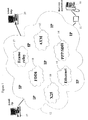
- FIG. 1 shows in general a preferred operating environment of a device according to an embodiment of the invention, as a block diagram.
- the operating environment comprises a terminal 10 that uses real-time applications, such as, e.g. VolP or packet-based video, which terminal can be, for example, a VolP phone, a videophone, a real-time interactive video conference application of a computer, etc.
- the terminal 10 is through an adapter 11 that may consist of, e.g. a gateway located in a Public Switched Telephone Network (PSTN), connected with an IP-based network 12 (IP cloud, Internet Protocol), such as, e.g. the Internet.
- IP cloud Internet Protocol
- the Internet is, in a simplified manner, a network formed of different networks, that supports TCP/IP-based applications, such as, e.g.
- the sub-networks that form the Internet can be, for example, ATM- 13 (Asynchronous Transfer Mode), PPP/SDH- 14 (Point-to-Point Protocol/Synchronous Digital Hierarchy), Ethernet- 15 (see, e.g. the standard IEEE 802.3), X25- 16 (standard of ITU-T), FR- 17 (Frame Relay), or FDDI-based 18 (Fiber Distributed Data Interface) networks. Attached to the Internet are users who use, for example, ftp- and emailbased applications 19 or, for example, telnet- and http-based (Hypertext Transfer Protocol) applications 20. It will be appreciated that the operating environment according to the invention is not restricted to what was presented above but, in reality, the Internet consists of a much larger number of users and networks.
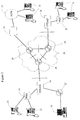
- FIG. 2 shows in general as a block diagram a preferred operating environment architecture (VoFR architecture)(Voice over Frame) of a device according to the invention, which operating environment comprises terminals 21 that utilise real-time applications and routers 29 that cause delays in the real-time data transmission between the terminals.
- the terminals 21 are attached to an ATM-based FR network 22, either through a Public Switched Telephone Network (PSTN) 23 along a gateway 24 or when the terminals are in a direct network connection, through a PBX 25 (private branch exchange) to a VFRAD device 26 (Voice Frame Delay Access Device) and from there further to the FR network.
- PSTN Public Switched Telephone Network
- PBX 25 private branch exchange
- VFRAD device 26 Voice Frame Delay Access Device
- the VFRAD enables the multiplexing/demultiplexing of data, voice and fax between different sources and applications and one network access point.
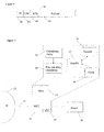
- FIG 3 there is illustrates by means of a diagram a preferred usage of a device according to the invention, in its operating environment.
- the operating environment consists of two parties in a real-time interactive connection with each other over a network - a sender 31 and a receiver 39. Since it is a question of an interactive connection between two parties, it is clear that the roles of the parties as a sender and a receiver may change during the connection.
- the sender 31 is in a real-time interactive data transmission connection, such as in, for example, a VolP connection with the receiver 39.
- samples are taken at suitable constant intervals by a sampler 32, which is, e.g.
- a microphone, a digital video camera or other corresponding sampler comprising an A/D converter for converting analog information into a digital format.
- the obtained samples are stored in an input buffer 33 to wait for transmission packing.
- the samples are directed to an encoder 34, which encodes them into a format transferable in the network, for example, frames them.
- the encoder From the encoder, the data packets are transmitted to a network 35 for being conveyed to the receiver 39.
- the flow of the data packets in the network is slowed down mainly due to queuing in routers 29 (in Figure 2) and the time taken by physical propagation.
- the time used for physical propagation may also vary in length for different data packets, or more precisely for data frames since, at this stage, the data packets are placed inside a frame, due to, e.g. the changing of the routing table of some router in the middle of the transmitting of a data burst, which thus directs the data packets that came in after the change along a route different to that used before the updating of the routing table.
- the data packets are transferred into a jitter buffer 36 through IP and UDP protocol stacks which remove from the data frame the fields that correspond to the protocols in question, to wait for their processing and transfer to a decoder 37.
- the terminal of the receiver takes from the buffer 36 samples when specific criteria are met and transfers them to the decoder 37, wherein the data frame is unpacked, and from there further to a player 38, such as, e.g. an audio playing application, video processing application of a computer, a combination of the D/A converter and speaker of a public switched telephone or other corresponding application comprising a D/A converter, for being converted from a digital format back into an analog format, for being processed and, thus, presented to the receiver.
- a player 38 such as, e.g. an audio playing application, video processing application of a computer, a combination of the D/A converter and speaker of a public switched telephone or other corresponding application comprising a D/A converter, for being converted from a digital format back into an analog format, for being processed and, thus, presented to the receiver.
- FIG. 4 shows in general a data frame 41 used in the data transmission of real-time data in IP-based data networks.
- the data frame comprises an IP header field 42, which comprises in general mainly information on the IP address of the sender and the receiver.
- IP header field After the IP header field, there follows, for example, a UDP header field 43 in the case of UDP-based data transmission, which is generally used by audio (speech) and video data transferred in an IP network.
- the UDP header field comprises information on the numbers of the ports of the sender and the receiver, and if desired, an additional data field checksum can be added to the field.
- the UDP header field is followed by an RTP header field 44, which comprises information, for example, on which application of the receiver the data packet is question is going to and information on how the data packet in question places itself in the data stream transferred to the same application, i.e. the sequence number of the data packet.
- the RTP header field is followed by an actual data packet 45 or a plurality of data packets transferred over the data network.
- FIG. 5 shows as a block diagram the description of a device according to the invention for timing the processing of data packets.
- the device comprises a telecommunication connection 51 to an IP-based data network 12, which telecommunication connection can be implemented, for example, through a public telephone network and a gateway, directly through a local network or through a wireless connection to the data network.
- a telecommunication connection 51 information is transferred to the device in data packets 45 that arrive inside data frames 41.
- the information arriving in the data packets is received in a Master Controlling Unit 52 (MCU), which is, for example, a microprocessor.
- the Master Controlling Unit is arranged, on the basis of a program stored in a memory 53, to store the data packet or data packets that arrived in the data frame in the memory 53.
- the Master Controlling Unit further comprises a clock 54, for example, the clock of a microprocessor for determining the course of time and functions implemented with programs stored in the memory 53 for calculating 55 the delay of a data packet from the difference between the time of transmission and the time of arrival and for calculating 56 a play-out delay on the bases of the delay values of the last n data packets.
- the Master Controlling Unit is arranged, on the basis of a program stored in the memory 53, to unpack the data frame with a decoder application on the basis of a response obtained from the clock.
- a transfer function 57 is stored in the memory for transferring data packets to the Master Controlling Unit for being processed and for being presented to the user by a player 38 on the basis of a response obtained from the clock of the reaching of a specific time limit.
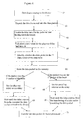
- Figure 6 represents with a flow diagram one preferred mode of operation of the method according to the invention, in which method a data frame 41 comes from a data network along a telecommunication connection to a device (step 61).
- the data frame is unpacked, i.e. the header fields comprised by the data frame are removed and the data packet itself is stored (step 62).
- the delay time of the data packet in question i.e. the play-out delay with which the voice sample contained by the packet could have been utilise is calculated and this delay time is stored in a memory, wherein the delay times of the n last arrived data packets are stored (step 63), where n is a natural number.
- a new value is calculated for the play-out delay on the basis of the updated last n delay times, with which play-out delay value, of the last n data packets arrived, a queue of m successive data packets at a maximum would have failed to arrive in time when delaying the initiation of the processing of the first data packet of a data burst for the duration of the play-out delay from its arrival and when processing the data packets following the first data packet of the data burst at sampling intervals after the processing of the first data packet (step 64).
- the value m mentioned above can preferably be, for example, 2 and said value n can preferably be, for example, of the order of some tens.
- an initial guess value is set as the value of the play-out delay, which preferably is, for example, the last play-out value used in the device at the previous occasion or some kind of other guess value, for example, on the basis of the factory settings.
- the data packet is the first data packet of a new data burst, such as, e.g. an audio (speech) burst or a video burst or whether it is a question of a data packet following the first data packet of the data burst (step 65).
- the data packet in question is stored in the memory of the device to wait for the data packet in question to be transferred for being processed (step 66).
- the processing time of the data packet in question has already passed the data packet is not stored but the delay time of the data packet is.
- steps 63-65 described above can also be preferably carried out in an order different from the one described above without problems and, thus, also these modes of implementation belong to the scope of the method according to the invention.
- step 67 If the data packet was the first data packet of a new data burst, said calculated new value of the play-out delay is set as the delay time monitored by the clock, calculated from the time the data packet in question arrived in the device (step 67). If the data packet was not the first data packet of the data burst, the sampling interval of the sender is set as the delay time monitored by the clock which normally, but not necessarily, is constant, starting the calculation from the transferring of the data packet preceding the data packet in question for being processed (step 68).
- the first data packet of the burst can be delayed for as long as desired without the quality of the audible speech suffering, however, with long delays real-time full duplexity would be lost, so there exists a maximum value for the delay value.
- the data packets following the first data packet of the data burst can no longer be delayed, but they must be processed or not be processed in case they have not arrived by a specific time, at specific intervals from each other. This interval is equal to the sampling interval at the sender's end of the connection.
- the delaying of others than the first data packet by deviating from the constant delay would be noticed as the "dragging" of speech when calling the receiver or correspondingly, the too fast playing of data packets would be noticed as speech faster than normal and sounding different.
- the Quality of Service known to the receiver would suffer as the audio sample separation differs from the sampling interval.
- the type of effect described above can also be easily noticed, for example, with a videotape recorder by slowing down the processing of the information stored on a videotape in the videotape recorder by pressing the (play) deceleration selector or correspondingly, by accelerating the processing of the information of the videotape.
- step 69 After setting the delay times, it is waited until the set delay time is fulfilled.
- the play-out delay from the arrival of the data packet in question in the device is reached (step 69).
- a time of the length of the sampling interval is reached from the transferring of the data packet preceding the data packet in question, or from the moment the temporally most recent data packet should have been transferred but failed, for example, to arrive within its transfer time and, thus, was not however transferred, for being processed (step 70).
- the play-out delay when the data packet is the first data packet of the data burst, or when the sampling interval, when the data packet is other than the first data packet of the data burst, expires the data packet in question is transferred for being processed, for example, to the player 38 or to some other application or means (step 71).
- the method described above could also be described as having two parts, whereupon the first part would be formed of the steps 61-66 and the second part would go and retrieve on the basis of the response obtained from the clock the data packet from the buffer, if the data packet had already arrived.
- the method would have a part that would take the information and data into the buffer and the memory, and a part that would retrieve the data and use the information stored in the memory for calculating the delays.
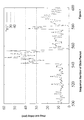
- Figure 7 shows an illustrative example of the relation of a play-out delay to the length of the queue formed of lost successive data packets.
- the vertical axis shows the value of the play-out delay used for delaying the first data packet of a data burst and, thus, of the whole data burst, in milliseconds and the horizontal axis informs the sequence numbers of the data packets of the data burst.
- the continuous line (marked “tr1") describes the delay of each data packet from the theoretic time of arrival calculated on the basis of the first data packet of the data burst and the sampling interval.
- the dashed lines (30 and 40) represent, with the play-out delay values of 30 and 40 milliseconds, whether the data packets arrive in time for being processed within the play-out delay values in question, if a data packet arrived above the dashed line, it would not have arrived in time for being processed within the delay time, and if it arrived below the dashed line, it would have arrived in time for being processed within the delay time.
- the longest queue formed of successive data packets that failed to arrive within the delay time for the play-out delay value of 30 milliseconds contains eight data packets (between the sequence numbers 540-560).
- the longest queue formed of successive data packets that failed to arrive within the delay time was only eight packets long.
- the loss of two successive data packets could be corrected by the codec used and, thus, with the play-out value of 40 milliseconds, the loss of data packets would not be detected in the connection.
- 40 milliseconds could indeed preferably be selected as the value of the play-out delay.
Landscapes
- Engineering & Computer Science (AREA)
- Computer Networks & Wireless Communication (AREA)
- Signal Processing (AREA)
- Multimedia (AREA)
- Computer Security & Cryptography (AREA)
- Data Exchanges In Wide-Area Networks (AREA)
Abstract
Description
- Conventionally, when calling by telephone speech has been transferred in circuit-switched networks, such as in a Public Switched Telephone Network (PSTN). When calling by telephone in a digital circuit-switched network, a (permanent) connection of 64 kbps (kilo bits per second) is established for each call. The constant band of a connection, 64 kbps, is due to the bit rate required in the sampling of analog speech when using 8-bit Pulse Code Modulation (PCM) at a sampling frequency of 8 kHz, which procedure enables the transmitting of analog speech of 300-3400 Hz in a digital format.
- The digital telephone network presented above which is currently in common use is, however, very ineffective and, thus, uses a lot of the network's resources. In the telephone network, the band of a connection is also reserved when the connection is not actively used, i.e. neither party of the connection is transferring information along the connection. This kind of use of a static band consumes a lot of data transmission resources as a result of which as the number of users increases, additional capacity must be invested in. In addition, the band is also wasted due to the ineffective Coding Scheme standardised in the telephone network. For example, G.729-coding manages sampling even at such a low bit rate as 8 kbps. Problems result from the kind of ineffectiveness described above particularly in calls between continents, where the increasing of data transmission capacity is not as easy as it is otherwise. The problem also manifests itself partly in the prices of calls; expensive investments in the capacity must be covered by high use charges.
- In particular, for connections between countries, instead of a static band reservation, so-called IP (Internet Protocol Telephony) calls have been started to be marketed. In an IP call, speech is converted first from an analog format into a digital format, it is compressed and finally converted into IP packets that are conveyed over an IP network sharing a band with the rest of IP traffic. In IP calls, a band can be used considerably more effectively than in calls that reserve a static band, which also shows in the prices of calls. Furthermore, also new more effective coding procedures can be used, such as, e.g. G.729-coding.
- In IP calls, a user can make a call by an ordinary telephone through a gateway to another ordinary telephone. The gateway delivers the call to the gateway of a receiver through an IP-based data network, such as, the Internet, from where the call is further directed through the receiver's local telephone network to the receiver. In the gateway of the receiver, the call is connected back to a public switched telephone network. A second alternative is the user being in a non-switched network connection to an IP-based data network, for example, through a local area network, whereupon user does not have to open a static audio band to a telephone network at all, but a router behind which user is, can route calls to the receiver in a manner of normal packet-based data transmission. IP calls are based on an Internet protocol with the help of which speech is transferred as packets over an IP network. This means that IP calls can be transferred, in principle, in any data network that uses IP protocol, for example, in the Internet, Intranets or local area networks.
- In IP calls, however, the Quality of Service (QoS) becomes a problem. The time of arrival of IP packets to a receiver is not known before the packets arrive. IP protocol routes the data flow packet-specifically due to which the delay of the packets in a network may vary greatly and the order of the packets may change. In addition, packets may be lost, for example, as a result of incoming data over flow that occur in the buffers of the routers. By using a reliable protocol, such as TCP (Transmission Control Protocol), packet losses like this can be identified automatically at the protocol level and the lost packets can be re-transmitted. However, the types of re-transmissions in question would continue to cause a varying delay as the packets pass through the network, so in IP calls UDP (User Datagram Protocol) protocol is normally used, where there are no re-transmissions. Thus, speech easily becomes fragmentary and incoherent as the delays between the packets grow although not a single packet would be lost on the way.
- A solution to this problem is presented, for example, in the publication Ramjee R., Kurose K., Towsley D. 1994. Adaptive Playout Mechanism for Packetized Audio Applications in Wide-Area Networks., where incoming packet-based audio (speech) data is buffered and the initiation of the calling of a uniform audio (speech) burst comprising a plurality of packets is delayed. A short-term delay trend calculated from the delay values of the packets that came in last, i.e. a moving average calculated from the delay values, is utilised in the determination of the length of the delay.
- However, such direct end-to-end delay management as this is, is not generally sufficient, for example, for ensuring the quality of an interactive real-time data stream. It is not sufficient to merely determine the delay so that only, for example, one per cent of the packets is lost, as in the model described above. It is also important to take into account the correlation between the lost packets, i.e. the so-called loss correlation. It is highly important as regards the quality of the connection whether packets are lost one here, another one there (no loss correlation) or several one after another (high loss correlation). The importance of loss correlation depends on the codec used because, for example, the codec used in a VolP (Voice over Internet Protocol) terminal, e.g. G.723.1, could be able to cover the loss of two successive packets by using Forward Error Correction (FEC), where the loss of three successive packets might cause an audible error. In this case, the method used should indeed be able to also take into consideration loss correlations of packets when deciding on the delay. However, the method reflecting prior art for buffer management does not take into account loss correlations between packets.
- Now, a method and a device have been invented for timing the processing of data packets, which improves, for example, the quality of speech of a real-time packet-based audio connection by also taking into consideration loss correlations between packets.
- According to a first aspect of the invention, a device has been implemented for timing the processing of data packets, comprising a memory for storing a data packet that comes to the device as part of a data burst, a clock for determining the course of time, and processing means for processing the data packet that exits the memory, characterised in that the device further comprises calculating means for calculating such a value for a play-out delay with which value, of the n temporally most recent data packets only m pieces would have failed to be received if the initiation of the processing of the data bursts comprising the data packets in question had been delayed for the duration of said play-out delay, where n and m are natural numbers, and transferring means for transferring the packets from the memory to the processing means on the basis of a response obtained from the clock of the reaching of said play-out delay value from the moment the data packet was received.
- According to a second aspect of the invention, a method has been implemented for timing the processing of data packets, the method comprising receiving a data packet that is part of a data burst, storing the received data packet in a memory, taking the data packet from the memory after a play-out delay from the receiving of the data packet, characterised in that the method comprises calculating a value for the play-out delay with which value of the play-out delay, of the n temporally most recent data packets only m pieces would have failed to be received if the initiation of the processing of the data bursts comprising the data packets in question had been delayed for the duration of said play-out delay, where n and m are natural numbers, and transferring the data packet from the memory to the processing means on the basis of a response obtained from the clock of the reaching of said play-out delay value from the receiving of the data packet.
- By the data burst is meant, in this connection, the continuous uninterrupted transmitting of bursty information, such as speech or video. Thus, the duration of a data burst is, for example, equal to the length for which a sender, for example, speaks continuously and thus, when the sender pauses while he is speaking, the data burst also stops. Different types of data bursts are, for example, an audio (speech) burst wherein bursty audio information is transmitted, and a video burst wherein bursty video picture is transmitted. Hence, even a high number of data packets may belong to a data burst, by which data packets is here understood primarily a digital sample taken from analog information, such as speech and picture. Whereas, in the following, by a data frame is understood, for example, when transmitting in an IP-based data network, a uniform entity formed of a header field placed around a data packet/data packets and the data packet/data packets.
- The device and method according to the invention are based on the assumptions of the limitation of the number of successive lost packets and the maximum play-out delay in the initiation of the processing of the first data packet of a data burst. The number limit of successively lost packets depends, for example, on the properties of the codec used. If the used codec is capable of correcting the loss of two successively lost data packets, the value two is used as the maximum number l max of the successively lost data packets, provided that there are no other factors influencing the matter. The play-out delay d again is set so that the number l of the successive lost data packets, viewed from the last n data packets received would be the maximum number l max of the successively lost data packets at the most, if only the maximum value d max of the play-out delay allows as high a play-out delay value as this.
- In general, it can be said that the number of successive lost packets decreases as the value of the play-out delay increases. In an extreme case, it could be thought the play-out delay to be so large that there would be time to receive the whole data burst before the initiation of the processing of the first data packet after the play-out delay from the receiving of the data packet in question, in which case not a single data packet would be lost due to the delay. However, as high a play-out delay value as this would wreck the full duplex, real-time and interactive nature of a connection. With high play-out delay values, the experienced Quality of Service (QoS) decreases, e.g. as the information, such as speech, transmitted by the parties that are in communication, overlaps. Determining the maximum value of the play-out delay is indeed a multi-goal optimisation task, the objective being minimising the play-out delay and the number of successively lost data packets, the solution of which normally changes as the conditions of the network change.
- In other words, in the method according to the invention, a value is calculated for a play-out delay d, which is the smallest possible value for which l ≤ lB max / B is true, however, so that d ≤ d max is true for the play-out delay, i.e. for which value it is true that it is smaller than or equal to the maximum value of the play-out value, or the number of lost successive data packets is smaller than or equal to the maximum value of lost successive data packets, if this can be achieved with the play-out delay which is smaller than the maximum value of the play-out delay.
- In the following, by the delay time of a data packet means the theoretic delay from the time of arrival of the data packet, as calculated from the arriving of the first data packet of a data burst to the device of a receiver. If k is the time of arrival of the first data packet of the data burst, and v is the sampling interval used by a sender, the theoretic time of arrival of the nth data packet of the data burst can be calculated from the equation the time of arrival = k + n * v, to which value the realised time of arrival is then compared for calculating the delay time. When using RTP protocol, whereupon the RTP header field of a data frame contains both the time stamp and sequence number of a data packet, the theoretic time of arrival can be calculated by comparing the time stamps of the first data packet of the data burst and the data packet that is the object of calculation to each other. This approach would indeed be unconditional if, for some reason, the sampling interval used by the sender was not constant within the data burst.
- In a preferred embodiment of the invention, the device and method are used in a network call for managing the delays of the data packets of data bursts. With the method according to the invention, the initiation of the processing of the first data packet of a data burst is delayed so much that estimated from the delay times of the data packets of the already arrived previous data bursts, of the n last already arrived data packets, a group of the length of m successive data packets at a maximum would have failed to arrive within the play-out delay. The device according to the invention can be a separate network telephone, a network videophone, a wireless telephone or other corresponding one, or it can utilise a processor, a microphone, speakers, a video card of a computer, etc. whereupon no separate device would be required in its implementation in practice, but it could be implemented programmably making use of the equipment commonly found in modem computers.
- With the invention, a reasonably easy and simple method and device are produced for timing the processing of data packets. The invention is particularly usable in real-time interactive communication through a data network, such as, e.g. the Internet. With the invention, it is possible to adapt more effectively than before at the receiving end to problems due to delays of varying lengths caused by stochastic network conditions and, thus, to improve the experienced Quality of Service (QoS). This is achieved, as distinct from the former, by taking into consideration in addition to the mere delays of data packets, also loss correlations between data packets that have not arrived, which may significantly influence the experienced Quality of Service.
- In the following, the invention will be described in detail by referring to the enclosed drawings, in which
- Figure 1 shows in general, as a block diagram, an operating environment according to the invention;
- Figure 2 shows in general as a block diagram, an architecture of a preferred operating environment according to the invention;
- Figure 3 shows a diagram of a preferred mode of operation of a device according to the invention, in its operating environment;
- Figure 4 shows in general a data frame used in the data transmission of real-time data in IP-based data networks;
- Figure 5 shows as a block diagram a description of a device according to the invention for timing the processing of data packets;
- Figure 6 describes by means of a flow diagram a preferred mode of operation of a method according to the invention; and
- Figure 7 shows an illustrative example of the relation between a play-out delay and the length of the queue formed of lost successive data packets.
-
- Figure 1 shows in general a preferred operating environment of a device according to an embodiment of the invention, as a block diagram. The operating environment comprises a terminal 10 that uses real-time applications, such as, e.g. VolP or packet-based video, which terminal can be, for example, a VolP phone, a videophone, a real-time interactive video conference application of a computer, etc. The terminal 10 is through an
adapter 11 that may consist of, e.g. a gateway located in a Public Switched Telephone Network (PSTN), connected with an IP-based network 12 (IP cloud, Internet Protocol), such as, e.g. the Internet. The Internet is, in a simplified manner, a network formed of different networks, that supports TCP/IP-based applications, such as, e.g. WWW (World Wide Web), SMTP (Simple Mail Transfer Protocol) email or FTP (File Transfer Protocol). The sub-networks that form the Internet can be, for example, ATM- 13 (Asynchronous Transfer Mode), PPP/SDH- 14 (Point-to-Point Protocol/Synchronous Digital Hierarchy), Ethernet- 15 (see, e.g. the standard IEEE 802.3), X25- 16 (standard of ITU-T), FR- 17 (Frame Relay), or FDDI-based 18 (Fiber Distributed Data Interface) networks. Attached to the Internet are users who use, for example, ftp- andemailbased applications 19 or, for example, telnet- and http-based (Hypertext Transfer Protocol)applications 20. It will be appreciated that the operating environment according to the invention is not restricted to what was presented above but, in reality, the Internet consists of a much larger number of users and networks. - Figure 2 shows in general as a block diagram a preferred operating environment architecture (VoFR architecture)(Voice over Frame) of a device according to the invention, which operating environment comprises
terminals 21 that utilise real-time applications androuters 29 that cause delays in the real-time data transmission between the terminals. Theterminals 21 are attached to an ATM-basedFR network 22, either through a Public Switched Telephone Network (PSTN) 23 along agateway 24 or when the terminals are in a direct network connection, through a PBX 25 (private branch exchange) to a VFRAD device 26 (Voice Frame Delay Access Device) and from there further to the FR network. The VFRAD enables the multiplexing/demultiplexing of data, voice and fax between different sources and applications and one network access point. On the other side of the VFRAD, there can also be arouter 27 of a local area network and behind therouter 27, a plurality ofterminals 28. - In Figure 3, there is illustrates by means of a diagram a preferred usage of a device according to the invention, in its operating environment. The operating environment consists of two parties in a real-time interactive connection with each other over a network - a
sender 31 and areceiver 39. Since it is a question of an interactive connection between two parties, it is clear that the roles of the parties as a sender and a receiver may change during the connection. Thesender 31 is in a real-time interactive data transmission connection, such as in, for example, a VolP connection with thereceiver 39. Of the analog information transmitted by the sender, for example, speech, samples are taken at suitable constant intervals by asampler 32, which is, e.g. a microphone, a digital video camera or other corresponding sampler comprising an A/D converter for converting analog information into a digital format. The obtained samples are stored in aninput buffer 33 to wait for transmission packing. From the input buffer, the samples are directed to anencoder 34, which encodes them into a format transferable in the network, for example, frames them. From the encoder, the data packets are transmitted to anetwork 35 for being conveyed to thereceiver 39. The flow of the data packets in the network is slowed down mainly due to queuing in routers 29 (in Figure 2) and the time taken by physical propagation. The time used for physical propagation may also vary in length for different data packets, or more precisely for data frames since, at this stage, the data packets are placed inside a frame, due to, e.g. the changing of the routing table of some router in the middle of the transmitting of a data burst, which thus directs the data packets that came in after the change along a route different to that used before the updating of the routing table. From the network, the data packets are transferred into ajitter buffer 36 through IP and UDP protocol stacks which remove from the data frame the fields that correspond to the protocols in question, to wait for their processing and transfer to adecoder 37. The terminal of the receiver takes from thebuffer 36 samples when specific criteria are met and transfers them to thedecoder 37, wherein the data frame is unpacked, and from there further to aplayer 38, such as, e.g. an audio playing application, video processing application of a computer, a combination of the D/A converter and speaker of a public switched telephone or other corresponding application comprising a D/A converter, for being converted from a digital format back into an analog format, for being processed and, thus, presented to the receiver. - Figure 4 shows in general a
data frame 41 used in the data transmission of real-time data in IP-based data networks. The data frame comprises anIP header field 42, which comprises in general mainly information on the IP address of the sender and the receiver. After the IP header field, there follows, for example, aUDP header field 43 in the case of UDP-based data transmission, which is generally used by audio (speech) and video data transferred in an IP network. The UDP header field comprises information on the numbers of the ports of the sender and the receiver, and if desired, an additional data field checksum can be added to the field. The UDP header field is followed by anRTP header field 44, which comprises information, for example, on which application of the receiver the data packet is question is going to and information on how the data packet in question places itself in the data stream transferred to the same application, i.e. the sequence number of the data packet. The RTP header field is followed by anactual data packet 45 or a plurality of data packets transferred over the data network. - Figure 5 shows as a block diagram the description of a device according to the invention for timing the processing of data packets. The device comprises a
telecommunication connection 51 to an IP-baseddata network 12, which telecommunication connection can be implemented, for example, through a public telephone network and a gateway, directly through a local network or through a wireless connection to the data network. Along thetelecommunication connection 51, information is transferred to the device indata packets 45 that arrive inside data frames 41. The information arriving in the data packets is received in a Master Controlling Unit 52 (MCU), which is, for example, a microprocessor. The Master Controlling Unit is arranged, on the basis of a program stored in amemory 53, to store the data packet or data packets that arrived in the data frame in thememory 53. Lower down, the figure shows the physical block diagram of theMaster Controlling Unit 52 and father up, the figure shows inside a dashed line the functional block diagram of theMaster Controlling Unit 52. The Master Controlling Unit further comprises aclock 54, for example, the clock of a microprocessor for determining the course of time and functions implemented with programs stored in thememory 53 for calculating 55 the delay of a data packet from the difference between the time of transmission and the time of arrival and for calculating 56 a play-out delay on the bases of the delay values of the last n data packets. The Master Controlling Unit is arranged, on the basis of a program stored in thememory 53, to unpack the data frame with a decoder application on the basis of a response obtained from the clock. In addition, atransfer function 57 is stored in the memory for transferring data packets to the Master Controlling Unit for being processed and for being presented to the user by aplayer 38 on the basis of a response obtained from the clock of the reaching of a specific time limit. - Figure 6 represents with a flow diagram one preferred mode of operation of the method according to the invention, in which method a
data frame 41 comes from a data network along a telecommunication connection to a device (step 61). In the device, the data frame is unpacked, i.e. the header fields comprised by the data frame are removed and the data packet itself is stored (step 62). On the basis of the data obtained from the data packet the delay time of the data packet in question, i.e. the play-out delay with which the voice sample contained by the packet could have been utilise is calculated and this delay time is stored in a memory, wherein the delay times of the n last arrived data packets are stored (step 63), where n is a natural number. A new value is calculated for the play-out delay on the basis of the updated last n delay times, with which play-out delay value, of the last n data packets arrived, a queue of m successive data packets at a maximum would have failed to arrive in time when delaying the initiation of the processing of the first data packet of a data burst for the duration of the play-out delay from its arrival and when processing the data packets following the first data packet of the data burst at sampling intervals after the processing of the first data packet (step 64). The value m mentioned above can preferably be, for example, 2 and said value n can preferably be, for example, of the order of some tens. - In the special case, where a data packet is the first data packet of the whole connection in question, whereupon there exists no information on the delay times of the earlier data packets of the connection, an initial guess value is set as the value of the play-out delay, which preferably is, for example, the last play-out value used in the device at the previous occasion or some kind of other guess value, for example, on the basis of the factory settings.
- After the calculation procedures of new values, it is further identified whether the data packet is the first data packet of a new data burst, such as, e.g. an audio (speech) burst or a video burst or whether it is a question of a data packet following the first data packet of the data burst (step 65). After this, the data packet in question is stored in the memory of the device to wait for the data packet in question to be transferred for being processed (step 66). Of course, in case the processing time of the data packet in question has already passed the data packet is not stored but the delay time of the data packet is.
- The steps 63-65 described above can also be preferably carried out in an order different from the one described above without problems and, thus, also these modes of implementation belong to the scope of the method according to the invention.
- If the data packet was the first data packet of a new data burst, said calculated new value of the play-out delay is set as the delay time monitored by the clock, calculated from the time the data packet in question arrived in the device (step 67). If the data packet was not the first data packet of the data burst, the sampling interval of the sender is set as the delay time monitored by the clock which normally, but not necessarily, is constant, starting the calculation from the transferring of the data packet preceding the data packet in question for being processed (step 68). For example, in an audio (speech) burst, the first data packet of the burst can be delayed for as long as desired without the quality of the audible speech suffering, however, with long delays real-time full duplexity would be lost, so there exists a maximum value for the delay value. However, the data packets following the first data packet of the data burst can no longer be delayed, but they must be processed or not be processed in case they have not arrived by a specific time, at specific intervals from each other. This interval is equal to the sampling interval at the sender's end of the connection. For example, in the case of speech, the delaying of others than the first data packet by deviating from the constant delay would be noticed as the "dragging" of speech when calling the receiver or correspondingly, the too fast playing of data packets would be noticed as speech faster than normal and sounding different. In both situations, the Quality of Service known to the receiver would suffer as the audio sample separation differs from the sampling interval. The type of effect described above can also be easily noticed, for example, with a videotape recorder by slowing down the processing of the information stored on a videotape in the videotape recorder by pressing the (play) deceleration selector or correspondingly, by accelerating the processing of the information of the videotape.
- After setting the delay times, it is waited until the set delay time is fulfilled. In the case of the first data packet of the data burst, it is waited that the play-out delay from the arrival of the data packet in question in the device is reached (step 69). In the case of other data packets of the data burst, it is waited that a time of the length of the sampling interval is reached from the transferring of the data packet preceding the data packet in question, or from the moment the temporally most recent data packet should have been transferred but failed, for example, to arrive within its transfer time and, thus, was not however transferred, for being processed (step 70). When the play-out delay, when the data packet is the first data packet of the data burst, or when the sampling interval, when the data packet is other than the first data packet of the data burst, expires the data packet in question is transferred for being processed, for example, to the
player 38 or to some other application or means (step 71). - The method described above could also be described as having two parts, whereupon the first part would be formed of the steps 61-66 and the second part would go and retrieve on the basis of the response obtained from the clock the data packet from the buffer, if the data packet had already arrived. Thus, the method would have a part that would take the information and data into the buffer and the memory, and a part that would retrieve the data and use the information stored in the memory for calculating the delays.
- Figure 7 shows an illustrative example of the relation of a play-out delay to the length of the queue formed of lost successive data packets. In the figure, the vertical axis shows the value of the play-out delay used for delaying the first data packet of a data burst and, thus, of the whole data burst, in milliseconds and the horizontal axis informs the sequence numbers of the data packets of the data burst. The continuous line (marked "tr1") describes the delay of each data packet from the theoretic time of arrival calculated on the basis of the first data packet of the data burst and the sampling interval. The dashed lines (30 and 40) represent, with the play-out delay values of 30 and 40 milliseconds, whether the data packets arrive in time for being processed within the play-out delay values in question, if a data packet arrived above the dashed line, it would not have arrived in time for being processed within the delay time, and if it arrived below the dashed line, it would have arrived in time for being processed within the delay time. As is shown in the figure, the longest queue formed of successive data packets that failed to arrive within the delay time for the play-out delay value of 30 milliseconds contains eight data packets (between the sequence numbers 540-560). For the play-out delay value of 40 milliseconds, the longest queue formed of successive data packets that failed to arrive within the delay time was only eight packets long. The loss of two successive data packets could be corrected by the codec used and, thus, with the play-out value of 40 milliseconds, the loss of data packets would not be detected in the connection. In this case, on the basis of the delay times shown in the figure, 40 milliseconds could indeed preferably be selected as the value of the play-out delay.
- This paper presents the implementation and embodiments of the present invention, with the help of examples. A person skilled in the art will appreciate that the present invention is not restricted to details of the embodiments presented above, and that the invention can also be implemented in another form without deviating from the characteristics of the invention. The embodiments presented above should be considered illustrative, but not restricting. Thus, the possibilities of implementing and using the invention are only restricted by the enclosed claims. Consequently, the various options of implementing the invention as determined by the claims, including the equivalent implementations, also belong to the scope of the invention.
Claims (19)
- A device for timing the processing of data packets, comprising a memory (53) for storing a data packet that arrives in the device as part of a data burst, a clock (54) for determining the course of time, and processing means (38) for processing the data packet that exits the memory, characterised in that the device further comprises calculating means (56) for calculating such a value for a play-out delay with which value of the n temporally most recent data packets only m pieces would have failed to be received if the initiation of the processing of the data bursts comprising the data packets in question had been delayed for the period of said play-out delay, where n and m are natural numbers, and transferring means (57) for transferring the packets from the memory to the processing means (38) on the basis of a response obtained from the clock of the reaching of said play-out delay value from the moment the data packet was received.
- A device according to claim 1, characterised in that the device further comprises a maximum value determined for the play-out delay and when the value of said play-out delay is higher than the maximum value determined for the play-out delay, the device is arranged to use the maximum value of the play-out delay as the value of the play-out delay.
- A device according to claim 1, characterised in that said data packet is the first data packet of a data burst.
- A device according to claim 3, characterised in that said transferring means (57) are arranged to transfer received data packets following the first data packet that belong to the same data burst from the memory after a delay from the moment the temporally most recent data packet was taken from the memory.
- A device according to claim 4, characterised in that said delay is a sampling interval.
- A device according to claim 1, characterised in that said data burst comprises real-time interactive data.
- A device according to claim 6, characterised in that the data burst comprises one of the following: packet video over IP, Voice over IP, audio/video streaming over IP.
- A device according to claim 1, characterised in that a duration of said data burst is equal to the time during which a sender transmits information uninterruptedly.
- A device according to claim 1, characterised in that said data packets are received from a data network through a real-time connection to some other party of the data network.
- A device according claim 1, characterised in that said device is a jitter buffer of a device that makes use of real-time information.
- A method for timing the processing of data packets, which method comprisesreceiving a data packet that is part of a data burst;storing the received data packet in a memory (53);taking the data packet from the memory after a play-out delay from the moment the data packet was received,
characterised in that the method comprisescalculating a value for the play-out delay with which value of the play-out delay, of the n temporally most recent data packets only m pieces would have failed to be received if the initiation of the processing of the data bursts comprising the data packets in question had been delayed for the duration of said play-out delay, where n and m are natural numbers; andtransferring the data packet from the memory to processing means (38) on the basis of a response obtained from a clock (54) of the reaching of said play-out delay value from the moment the data packet was received. - A method according to claim 11, characterised in that, in addition, a maximum value is determined for the play-out delay, and when the value of said play-out delay is higher than the maximum value determined for the play-out delay, the maximum value of the play-out delay is used as the value of the play-out delay.
- A method according to claim 11, characterised in that said data packet is the first data packet of the data burst.
- A method according to claim 13, characterised in that the method comprises
taking received data packets following the first data packet that belong to the same data burst from the memory after a delay from the moment the temporally most recent data packet was taken from the memory. - A method according to claim 14, characterised in that said delay is a sampling interval.
- A method according to claim 11, characterised in that said data burst comprises real-time interactive data.
- A method according to claim 16, characterised in that the data burst comprises one of the following: packet video over IP, Voice over IP, audio/video streaming over IP.
- A method according to claim 11, characterised in that a duration of said data burst is equal to the time during which a sender transmits information uninterruptedly.
- A method according to claim 11, characterised in that said data packets are received from a data network through a real-time connection to some other party of the data network.
Applications Claiming Priority (2)
| Application Number | Priority Date | Filing Date | Title |
|---|---|---|---|
| FI992834A FI108692B (en) | 1999-12-30 | 1999-12-30 | Method and apparatus for scheduling processing of data packets |
| FI992834 | 1999-12-30 |
Publications (2)
| Publication Number | Publication Date |
|---|---|
| EP1113645A2 true EP1113645A2 (en) | 2001-07-04 |
| EP1113645A3 EP1113645A3 (en) | 2009-04-08 |
Family
ID=8555846
Family Applications (1)
| Application Number | Title | Priority Date | Filing Date |
|---|---|---|---|
| EP00660156A Withdrawn EP1113645A3 (en) | 1999-12-30 | 2000-09-13 | A method and device for timing the processing of data packets |
Country Status (3)
| Country | Link |
|---|---|
| US (1) | US6977942B2 (en) |
| EP (1) | EP1113645A3 (en) |
| FI (1) | FI108692B (en) |
Cited By (4)
| Publication number | Priority date | Publication date | Assignee | Title |
|---|---|---|---|---|
| US7782813B2 (en) | 2002-06-07 | 2010-08-24 | Ember Corporation | Monitoring network traffic |
| WO2013079097A1 (en) * | 2011-11-29 | 2013-06-06 | Huawei Technologies Co., Ltd. | Delay timer device, method for managing a plurality of delays, and apparatus for delaying a plurality of data packets |
| US8503465B2 (en) | 2007-09-17 | 2013-08-06 | Qualcomm Incorporated | Priority scheduling and admission control in a communication network |
| US8688129B2 (en) | 2007-09-17 | 2014-04-01 | Qualcomm Incorporated | Grade of service (GoS) differentiation in a wireless communication network |
Families Citing this family (35)
| Publication number | Priority date | Publication date | Assignee | Title |
|---|---|---|---|---|
| US7373413B1 (en) * | 2000-06-28 | 2008-05-13 | Cisco Technology, Inc. | Devices and methods for minimizing start up delay in transmission of streaming media |
| US20040057382A1 (en) * | 2000-10-09 | 2004-03-25 | Anurag Kumar | Method of distributed voice transmission |
| US7149187B1 (en) * | 2000-12-28 | 2006-12-12 | Cisco Technology, Inc. | Random early detection policer using randomization of packet drops |
| US20020172229A1 (en) * | 2001-03-16 | 2002-11-21 | Kenetec, Inc. | Method and apparatus for transporting a synchronous or plesiochronous signal over a packet network |
| US7453897B2 (en) * | 2001-10-03 | 2008-11-18 | Global Ip Solutions, Inc. | Network media playout |
| US7283475B2 (en) * | 2001-10-19 | 2007-10-16 | Bbn Technologies Corp. | Fractal dimension analysis for data stream isolation |
| US7574597B1 (en) | 2001-10-19 | 2009-08-11 | Bbn Technologies Corp. | Encoding of signals to facilitate traffic analysis |
| US7162418B2 (en) * | 2001-11-15 | 2007-01-09 | Microsoft Corporation | Presentation-quality buffering process for real-time audio |
| US7263109B2 (en) * | 2002-03-11 | 2007-08-28 | Conexant, Inc. | Clock skew compensation for a jitter buffer |
| US20050249185A1 (en) * | 2002-06-07 | 2005-11-10 | Poor Robert D | Routing in wireless networks |
| EP1525666A4 (en) * | 2002-06-07 | 2007-06-20 | Ember Corp | Ad hoc wireless network using gradient routing |
| US20050226195A1 (en) * | 2002-06-07 | 2005-10-13 | Paris Matteo N | Monitoring network traffic |
| US20050249186A1 (en) * | 2002-06-07 | 2005-11-10 | Kelsey Richard A | Routing in an asymmetrical link wireless network |
| US7269141B2 (en) * | 2002-09-24 | 2007-09-11 | Accton Technology Corporation | Duplex aware adaptive playout method and communications device |
| US7245608B2 (en) * | 2002-09-24 | 2007-07-17 | Accton Technology Corporation | Codec aware adaptive playout method and playout device |
| US7474624B2 (en) * | 2003-05-29 | 2009-01-06 | Motorola, Inc. | Method and apparatus for reducing delay jitter |
| US7852993B2 (en) * | 2003-08-11 | 2010-12-14 | Microsoft Corporation | Speech recognition enhanced caller identification |
| EP1678853A2 (en) * | 2003-10-03 | 2006-07-12 | Quantum Trading Analytics, Inc. | Method and apparatus for measuring network timing and latency |
| US7778225B2 (en) * | 2003-10-08 | 2010-08-17 | Research In Motion Limited | Method and apparatus for dynamic packet transport in CDMA2000 networks |
| KR100631201B1 (en) * | 2004-02-11 | 2006-10-04 | 삼성전자주식회사 | Method of cost-based routing using backoff scheme |
| WO2005079536A2 (en) * | 2004-02-19 | 2005-09-01 | Ember Corporation | Directing packets in a mesh network |
| WO2005079539A2 (en) * | 2004-02-19 | 2005-09-01 | Ember Corporation | Dynamic identification of nodes in a network |
| US7466692B2 (en) * | 2004-09-09 | 2008-12-16 | Alcatel-Lucent Usa Inc. | Method and apparatus for performing quality-of-service calculations on packet-based networks |
| US7529189B2 (en) * | 2005-09-29 | 2009-05-05 | Via Technologies, Inc. | Mechanism for imposing a consistent delay on information sets received from a variable rate information stream |
| US7742413B1 (en) * | 2006-02-01 | 2010-06-22 | Sprint Communications Company, L.P. | Utilizing a null jitter buffer to monitor session traffic |
| US8213444B1 (en) | 2006-02-28 | 2012-07-03 | Sprint Communications Company L.P. | Adaptively adjusting jitter buffer characteristics |
| GB0705329D0 (en) * | 2007-03-20 | 2007-04-25 | Skype Ltd | Method of transmitting data in a communication system |
| US7948897B2 (en) * | 2007-08-15 | 2011-05-24 | Adc Telecommunications, Inc. | Delay management for distributed communications networks |
| US8160104B2 (en) * | 2008-08-11 | 2012-04-17 | Research In Motion Ltd. | System and method for communicating using an in-vehicle system |
| US8743718B2 (en) | 2011-06-21 | 2014-06-03 | Adc Telecommunications, Inc. | End-to-end delay management for distributed communications networks |
| GB2520866B (en) | 2011-10-25 | 2016-05-18 | Skype Ltd | Jitter buffer |
| JP2013134119A (en) * | 2011-12-26 | 2013-07-08 | Sony Corp | Transmitter, transmission method, receiver, reception method, synchronous transmission system, synchronous transmission method, and program |
| US9450689B2 (en) | 2013-10-07 | 2016-09-20 | Commscope Technologies Llc | Systems and methods for delay management in distributed antenna system with direct digital interface to base station |
| FR3053196A1 (en) | 2016-06-24 | 2017-12-29 | Orange | METHOD FOR UDP COMMUNICATION VIA MULTIPLE PATHS BETWEEN TWO TERMINALS |
| FR3053197A1 (en) * | 2016-06-24 | 2017-12-29 | Orange | METHOD FOR UDP COMMUNICATION VIA MULTIPLE PATHS BETWEEN TWO TERMINALS |
Citations (1)
| Publication number | Priority date | Publication date | Assignee | Title |
|---|---|---|---|---|
| US5623483A (en) * | 1995-05-11 | 1997-04-22 | Lucent Technologies Inc. | Synchronization system for networked multimedia streams |
Family Cites Families (24)
| Publication number | Priority date | Publication date | Assignee | Title |
|---|---|---|---|---|
| AU1572995A (en) | 1994-02-11 | 1995-08-29 | Newbridge Networks Corporation | Method of dynamically compensating for variable transmission delays in packet networks |
| US5768527A (en) * | 1996-04-23 | 1998-06-16 | Motorola, Inc. | Device, system and method of real-time multimedia streaming |
| US6400681B1 (en) * | 1996-06-20 | 2002-06-04 | Cisco Technology, Inc. | Method and system for minimizing the connection set up time in high speed packet switching networks |
| US5963551A (en) * | 1996-09-30 | 1999-10-05 | Innomedia Pte Ltd. | System and method for dynamically reconfigurable packet transmission |
| US6304567B1 (en) * | 1996-11-26 | 2001-10-16 | Lucent Technologies Inc. | Methods and apparatus for providing voice communications through a packet network |
| US6282196B1 (en) * | 1997-04-14 | 2001-08-28 | Lucent Technologies Inc. | Dynamic build-out approach for use in packet voice systems |
| JPH114292A (en) * | 1997-06-12 | 1999-01-06 | Hitachi Ltd | Communication system |
| US6360271B1 (en) * | 1999-02-02 | 2002-03-19 | 3Com Corporation | System for dynamic jitter buffer management based on synchronized clocks |
| US6366959B1 (en) * | 1997-10-01 | 2002-04-02 | 3Com Corporation | Method and apparatus for real time communication system buffer size and error correction coding selection |
| US6434606B1 (en) * | 1997-10-01 | 2002-08-13 | 3Com Corporation | System for real time communication buffer management |
| EP0921666A3 (en) | 1997-12-02 | 1999-07-14 | Nortel Networks Corporation | Speech reception via a packet transmission facility |
| US6301258B1 (en) * | 1997-12-04 | 2001-10-09 | At&T Corp. | Low-latency buffering for packet telephony |
| US6219339B1 (en) * | 1998-02-20 | 2001-04-17 | Lucent Technologies Inc. | Method and apparatus for selectively discarding packets |
| US6259691B1 (en) * | 1998-07-24 | 2001-07-10 | 3Com Corporation | System and method for efficiently transporting dual-tone multi-frequency/multiple frequency (DTMF/MF) tones in a telephone connection on a network-based telephone system |
| US6259677B1 (en) * | 1998-09-30 | 2001-07-10 | Cisco Technology, Inc. | Clock synchronization and dynamic jitter management for voice over IP and real-time data |
| EP1141798B1 (en) | 1999-01-14 | 2003-04-02 | Siemens Aktiengesellschaft | Control method and numerical control for the vibration-reduced acceleration of a movable machine part |
| US6452950B1 (en) * | 1999-01-14 | 2002-09-17 | Telefonaktiebolaget Lm Ericsson (Publ) | Adaptive jitter buffering |
| US6512761B1 (en) * | 1999-02-02 | 2003-01-28 | 3Com Corporation | System for adjusting billing for real-time media transmissions based on delay |
| US6584104B1 (en) * | 1999-07-06 | 2003-06-24 | Lucent Technologies, Inc. | Lost-packet replacement for a digital voice signal |
| US6574213B1 (en) * | 1999-08-10 | 2003-06-03 | Texas Instruments Incorporated | Wireless base station systems for packet communications |
| US6570849B1 (en) * | 1999-10-15 | 2003-05-27 | Tropic Networks Inc. | TDM-quality voice over packet |
| US6665317B1 (en) * | 1999-10-29 | 2003-12-16 | Array Telecom Corporation | Method, system, and computer program product for managing jitter |
| US6704329B2 (en) * | 2001-05-08 | 2004-03-09 | Path 1 Network Technologies Inc. | Minimizing the effect of jitter upon the quality of service operation of networked gateway devices |
| US7269141B2 (en) * | 2002-09-24 | 2007-09-11 | Accton Technology Corporation | Duplex aware adaptive playout method and communications device |
-
1999
- 1999-12-30 FI FI992834A patent/FI108692B/en not_active IP Right Cessation
-
2000
- 2000-09-13 EP EP00660156A patent/EP1113645A3/en not_active Withdrawn
- 2000-12-27 US US09/749,055 patent/US6977942B2/en not_active Expired - Fee Related
Patent Citations (1)
| Publication number | Priority date | Publication date | Assignee | Title |
|---|---|---|---|---|
| US5623483A (en) * | 1995-05-11 | 1997-04-22 | Lucent Technologies Inc. | Synchronization system for networked multimedia streams |
Non-Patent Citations (2)
| Title |
|---|
| PINTO J ET AL: "An algorithm for playout of packet voice based on adaptive adjustment of talkspurt silence periods" LOCAL COMPUTER NETWORKS, 1999. LCN '99. CONFERENCE ON LOWELL, MA, USA 18-20 OCT. 1999, LOS ALAMITOS, CA, USA,IEEE COMPUT. SOC, US, 18 October 1999 (1999-10-18), pages 224-231, XP010358540 ISBN: 978-0-7695-0309-7 * |
| RAMJEE R ET AL: "Adaptive playout mechanisms for packetized audio applications in wide-area networks" INFOCOM '94. NETWORKING FOR GLOBAL COMMUNICATIONS., 13TH PROCEEDINGS I EEE TORONTO, ONT., CANADA 12-16 JUNE 1994, LOS ALAMITOS, CA, USA,IEEE COMPUT. SOC, 12 June 1994 (1994-06-12), pages 680-688, XP010098440 ISBN: 978-0-8186-5570-8 * |
Cited By (8)
| Publication number | Priority date | Publication date | Assignee | Title |
|---|---|---|---|---|
| US7782813B2 (en) | 2002-06-07 | 2010-08-24 | Ember Corporation | Monitoring network traffic |
| US8000288B2 (en) | 2002-06-07 | 2011-08-16 | Ember Corporation | Monitoring network traffic |
| US8503465B2 (en) | 2007-09-17 | 2013-08-06 | Qualcomm Incorporated | Priority scheduling and admission control in a communication network |
| US8688129B2 (en) | 2007-09-17 | 2014-04-01 | Qualcomm Incorporated | Grade of service (GoS) differentiation in a wireless communication network |
| WO2013079097A1 (en) * | 2011-11-29 | 2013-06-06 | Huawei Technologies Co., Ltd. | Delay timer device, method for managing a plurality of delays, and apparatus for delaying a plurality of data packets |
| CN104115457A (en) * | 2011-11-29 | 2014-10-22 | 华为技术有限公司 | Delay timer device, method for managing a plurality of delays, and apparatus for delaying a plurality of data packets |
| US9391904B2 (en) | 2011-11-29 | 2016-07-12 | Huawei Technologies Co., Ltd. | Delay timer device, method for managing a plurality of delays, and apparatus for delaying a plurality of data packets |
| CN104115457B (en) * | 2011-11-29 | 2017-08-25 | 华为技术有限公司 | The device of time delay timing device, the method for the multiple time delays of management and the multiple packets of delay |
Also Published As
| Publication number | Publication date |
|---|---|
| FI108692B (en) | 2002-02-28 |
| EP1113645A3 (en) | 2009-04-08 |
| US20010012300A1 (en) | 2001-08-09 |
| FI19992834A (en) | 2001-07-01 |
| US6977942B2 (en) | 2005-12-20 |
Similar Documents
| Publication | Publication Date | Title |
|---|---|---|
| US6977942B2 (en) | Method and a device for timing the processing of data packets | |
| US6570849B1 (en) | TDM-quality voice over packet | |
| US6778493B1 (en) | Real-time media content synchronization and transmission in packet network apparatus and method | |
| EP1206082B1 (en) | Packet processor and recording medium with packet processing programs thereon | |
| US7079486B2 (en) | Adaptive threshold based jitter buffer management for packetized data | |
| US6157653A (en) | Method and apparatus for adaptive smoothing delay for packet voice applications | |
| US6360271B1 (en) | System for dynamic jitter buffer management based on synchronized clocks | |
| US7161939B2 (en) | Method and system for switching among independent packetized audio streams | |
| US6859460B1 (en) | System and method for providing multimedia jitter buffer adjustment for packet-switched networks | |
| US6512761B1 (en) | System for adjusting billing for real-time media transmissions based on delay | |
| US7379466B2 (en) | In band signal detection and presentation for IP phone | |
| US20140376545A1 (en) | Implementing a High Quality VOIP Device | |
| EP0921666A2 (en) | Speech reception via a packet transmission facility | |
| US7769054B2 (en) | Method of conducting a communications session using incorrect timestamps | |
| US7200113B2 (en) | Apparatus and method for isochronous network delay compensation | |
| US7542465B2 (en) | Optimization of decoder instance memory consumed by the jitter control module | |
| Yu et al. | Design and traffic engineering of VoIP for enterprise and carrier networks | |
| Francis‐Cobley et al. | Voice over IP versus voice over frame relay | |
| CN104702807A (en) | VoIP communication system | |
| Yletyinen | The quality of voice over ip | |
| JP4667811B2 (en) | Voice communication apparatus and voice communication method | |
| JP3669660B2 (en) | Call system | |
| JP2005252429A (en) | Ip packetizing unit | |
| Hunt et al. | QoS requirements for a voice-over-IP PSTN | |
| Luoma et al. | Quality of service for IP voice services: is it necessary? |
Legal Events
| Date | Code | Title | Description |
|---|---|---|---|
| PUAI | Public reference made under article 153(3) epc to a published international application that has entered the european phase |
Free format text: ORIGINAL CODE: 0009012 |
|
| AK | Designated contracting states |
Kind code of ref document: A2 Designated state(s): AT BE CH CY DE DK ES FI FR GB GR IE IT LI LU MC NL PT SE |
|
| AX | Request for extension of the european patent |
Free format text: AL;LT;LV;MK;RO;SI |
|
| RAP1 | Party data changed (applicant data changed or rights of an application transferred) |
Owner name: NOKIA SIEMENS NETWORKS OY |
|
| PUAL | Search report despatched |
Free format text: ORIGINAL CODE: 0009013 |
|
| AK | Designated contracting states |
Kind code of ref document: A3 Designated state(s): AT BE CH CY DE DK ES FI FR GB GR IE IT LI LU MC NL PT SE |
|
| AX | Request for extension of the european patent |
Extension state: AL LT LV MK RO SI |
|
| RIC1 | Information provided on ipc code assigned before grant |
Ipc: H04L 12/64 20060101ALI20090303BHEP Ipc: H04L 12/56 20060101ALI20090303BHEP Ipc: H04L 29/06 20060101AFI20010323BHEP |
|
| AKX | Designation fees paid | ||
| REG | Reference to a national code |
Ref country code: DE Ref legal event code: 8566 |
|
| STAA | Information on the status of an ep patent application or granted ep patent |
Free format text: STATUS: THE APPLICATION IS DEEMED TO BE WITHDRAWN |
|
| 18D | Application deemed to be withdrawn |
Effective date: 20091009 |